Yaskawa Auto Tuning
Prerequisites
- Have a tuning cable. USB Micro b connector to fit the servo drive.

- Download and install SigmaWin+
- https://www.yaskawa.com/products/motion/sigma-5-servo-products/software-tools/sigmawinplus/-/content/_6c2e204d-20bc-475d-84a3-8f471d3ccaf7_DownloadSoftware
- Copy over USB folder (M:\Production\Products\Drives-Servo\Yaskawa\Software\SigmaWinPlus570a)
- Check device manager in the usb section or unrecognized device section to find the yaskawa drive. update the driver manually, looking in the USB folder copied over.
- Open SigmaWin+ and connect to drive
- If drive is not showing, go to device manager and find the yaskawa drive and update drivers (found on server: M:\Production\Products\Drives-Servo\Yaskawa\Software)
- Default drive parameters are on the server: M:\Production\Products\Drives-Servo\Yaskawa\Drive Parameters, and you should not assume that the drives ship with correct default parameters.
Leave the drives in tuning less mode if running under 200ipm or if precise profiling is not needed.
Basic Auto-Tuning
Note: To tune a gantry mode using auto tuning, you can decouple one of the motors on the gantry.
Tuning Setup
- Search and connect to the drive
- Keep hardware enable on, but turn off drive enable. Do that with one of the following methods:
- For rapidpath systems, enable the machine. Then press the Disable button under the Service -> Maintenance page.
- Set "Turn Off Enable Signals upon Disable" to "Drive Enable" in Interface Config or Configure->Plugins->MachMotion.
Press Save and disable the software.
- Or if necessary, pull the control cable out from the drive.
- Set In Position Parameter Pn522
- For RapidPath calculate (PnB02) x (Steps Per) x (Resolution) = Pn522
- For Apollo III calculate (Steps Per) x (Resolution)= Pn522
"Resolution" = Max Position Error that you want to see. Maybe 0.001 Inch
- Select Tuning --> Tuning to begin the tuning process
- Click the Execute Button.

- If it isn't in tuning mode already, you will have to enter tuning less mode. Press OK and then cycle power on the drive.

- Click the Execute button to calculate inertia. NOTE: If worse than 400% (4:1 ratio), your motor will likely not work. Call MachMotion for engineering.

- Select the No Reference Input Option in the Autotuning Area and then click the Autotuning
Button.

- Configure Conditions


-
- Choose "1: A moment of inertia is not presumed" (We already calculated the inertia above)
- Choose "1: Standard"
- Choose appropriate mechanism. Default use Belt Mechanism even for ball screw unless you need very rigid tuning.
- Edit distance if necessary (3 revs is default)
- Select "Start tuning using the default settings" (can be done without this option, but this is the typical way to do your first tune).
- Select "Next"


Tuning Process
- Turn the "Servo ON"
- Select "Start Tuning"
- Software will run the motor through it's pre-programmed moves
- Click "Finish"
- The drive is tuned
- Click "Finish" again to exit tuning mode
If tuning fails it could be caused from one of the following reasons:
The position tolerance is too small. Increase Pn522 to allow for more position error.
Final Parameter Setup
- Turn off model following by setting Pn140 digit 0 to 0.
- Set feed forward gain Pn109 to 0%. unless you are trying to work around very High inertia, then try 75%
- Check the following parameters on all axis that drive the tool usually X, Y and Z, (Exclude things like tool changers).
- Pn100 (Speed Loop Gain)
- Pn101 (Speed loop integral time constant
- Pn102 (Position Loop Gain)
- Pick the Highest value for Pn101 and the lowest for Pn100 and 102 from all axes values.
- Then make all included drives match each parameter.
Pn100- Lowest
Pn101- Highest
Pn102- Lowest
System Tuning
Manually Setting Inertia Parameters
On a gantry machine or other arrangement where multiple motors are physically connected together, you can't use a standard inertia tune to calculate moment of inertia.
See the attached date sheets for motor information. SGM7A motors start at Page 75 of the Sigma-7 document. SGMXA motors start at Page 78 of the Sigma-X document that can be found at this link, it was too large to attach to this document. With some digging, these sheets will give you the "Rotor Moment of Inertia" and "Rated Torque". In the example below we're working with a SGMXA-25A... motor.
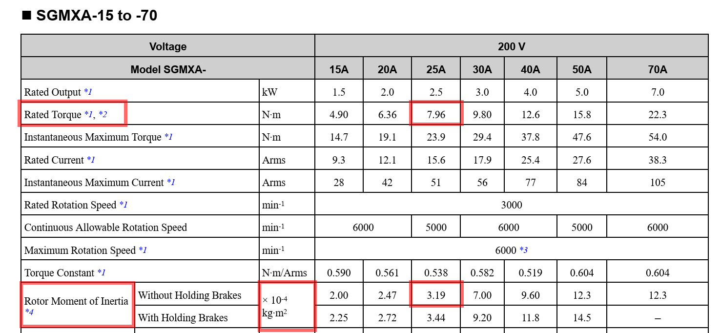
Pay attention to the exponents. On this motor the inertia is listed in the sheet as units of ×10^4 kg∙m2 so you would enter in =3.19*10^-4
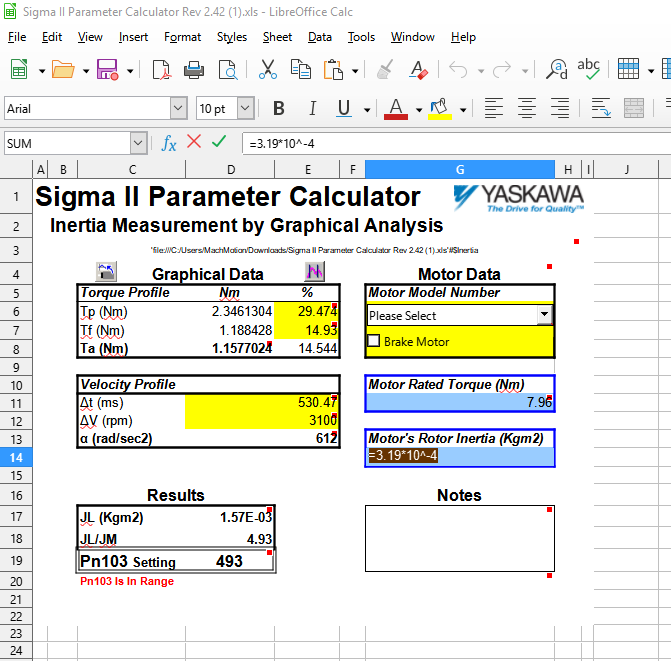
Search the internet for "Sigma II Parameter Calculator" or use the attached sheet.
If you download the sheet from the internet you may need to unlock sheets to make modifications.
The cells with fill color are expected to be filled by you. Tp, Tf, Δt, ΔV, Motor Rated Torque and Motor's Rotor Inertia. Don't use the Motor model number drop down since it's for Sigma-2.
Torque and Velocity Profiles will be gotten from a trace in SigmaWin. Connect to the drive and setup a trace similar to the settings below. Note that you'll trace and record both axes to get inertia values for each. They could be different
For better results, center up the Y axis on the gantry and match pinion engagements on each side. This will get the 2 motors in as close to the same setup physically as possible.
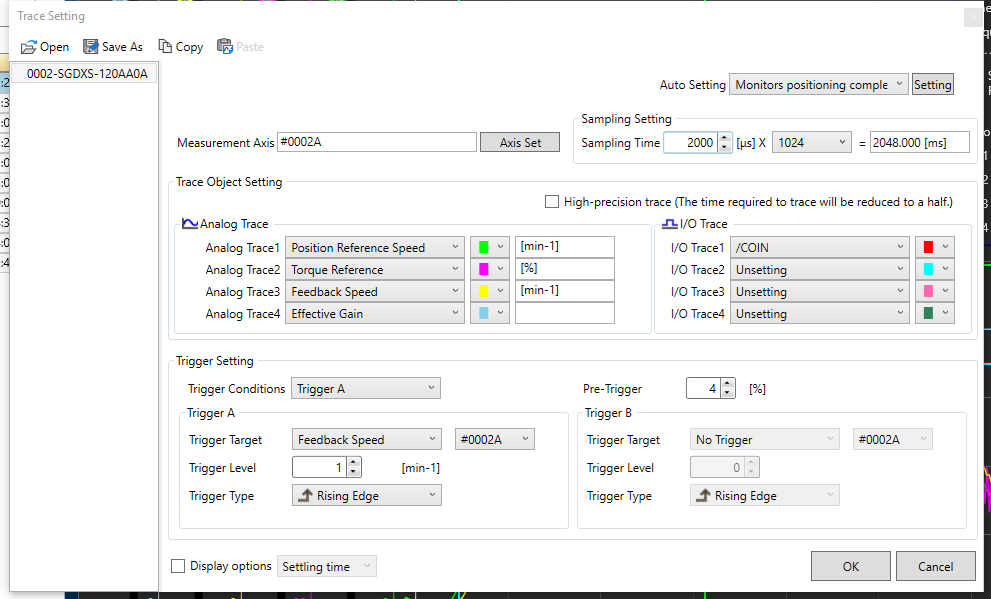
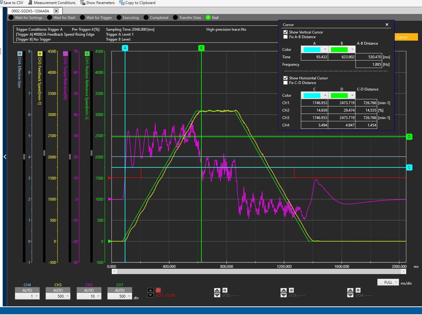
Trace with Speed(yellow) and Torque(purple)
Measure horizontally along the approximate centerline of torque during acceleration.
Enter into Tp (Torque Peak) % of torque during acceleration (Ch:2 - D)
Measure horizontally along the approximate centerline of torque showing the friction during the move at speed.
Enter into Tf (Torque Friction) % of torque at end of acceleration during move (Ch:2 - C)
Enter into ΔV RPM, the RPM during the move at speed. I don't have a horizontal line here on the trace above, I just approximated the motor stabilized at 3100 RPM during the move looking at the scaling on the left.
Measure speed vertically from start of movement to end of acceleration
Enter into ΔT time (ms) spent in acceleration (A-B Distance)
Enter in the calculated Pn103 for each motor and program those in the drives.
System Tuning for Gantry
- Manually calculate the inertia (Pn103)
- Do a system tune. Ramp up till it gets noisy.
- Example values: FF 170, FB 48.
- Pull back the tune till it sounds good.
- Try to minimize following error.
- Graph following error.
- Check the following error both axes.
- Increase the FF gain by 10s on the non gantry axis to make the following errors match.
Custom Tuning
- Enable Tuning Mode
- Run Auto Inertia test (Pn103)
- Custom Tuning
- Make following errors match
Advanced Tuning
If additional tuning is required, you can run through the same procedure above but modify selections on Mode Selection and Mechanical Selection.
You may have to play with Pn100-Pn102. But MachMotion strongly recommends keeping the parameters matching in both drives.
- Pn100 (Speed Loop Gain)
- Increase to help make the machine more smooth.
- Pn101 (Speed loop integral time constant
- Increase to reduce rigidity and noise.
- Pn102 (Position Loop Gain)
- Increase till following error stops decreasing.
You can also go through Chapter 8 (Tuning) of the attached manual ("Sigma-7 Manual Analog-Pulse.pdf").
If auto tuning does not work, you may have to try manual tuning.
Manual/Automatic Gain Switching (Sigma X)
Manual Gain Switching
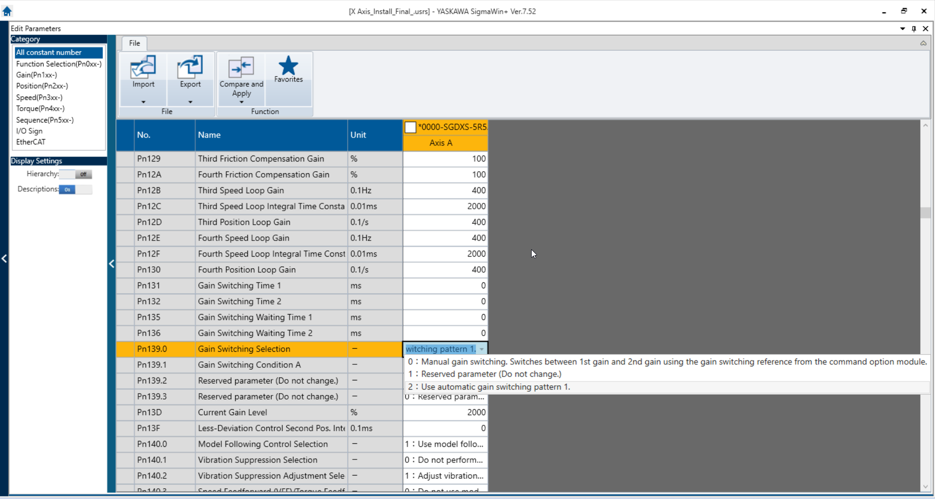
Pn139.0 dictates which type of, if any, Gain Switching is active.
Option "0: Manual Gain Switching" allows Mach to send an EtherCAT signal to the drive that can swap between the 4 Gain parameter sets:
Gain Set 1: Pn100, Pn101, Pn102
Gain Set 2: Pn104, Pn105, Pn106
Gain Set 3: Pn12B, Pn12C, Pn12D
Gain Set 4: Pn12E, Pn12F, Pn130
This allows Mach to swap to different Gain values on the fly to get different response and performance behaviors for different operations. (EX. Rigid Tapping, Laser Etching, Smooth Shape-Cutting, etc.). Mach will be able to do this with M-Codes (TBD by Andy).
Automatic Gain Switching
Option "2: Use automatic Gain Switching pattern 1" will automatically cycle the active Gain Set between 1 and 2 when the condition set in Pn139.1 is true.
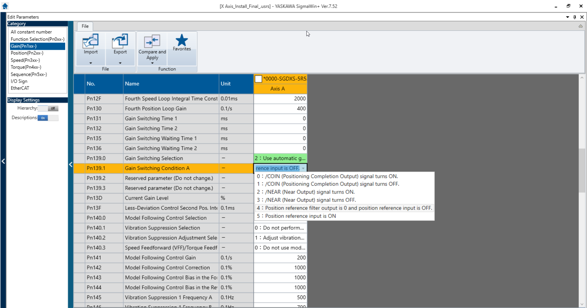
Pn139.1 dictates the condition that needs to be true in order for Automatic Gain Switching to take effect. We currently plan to use "4: Position Reference output is 0 and position reference input is off". This will allow us to swap to a softer set of gains when the motors are not in motion and eliminate the harmonic hum.
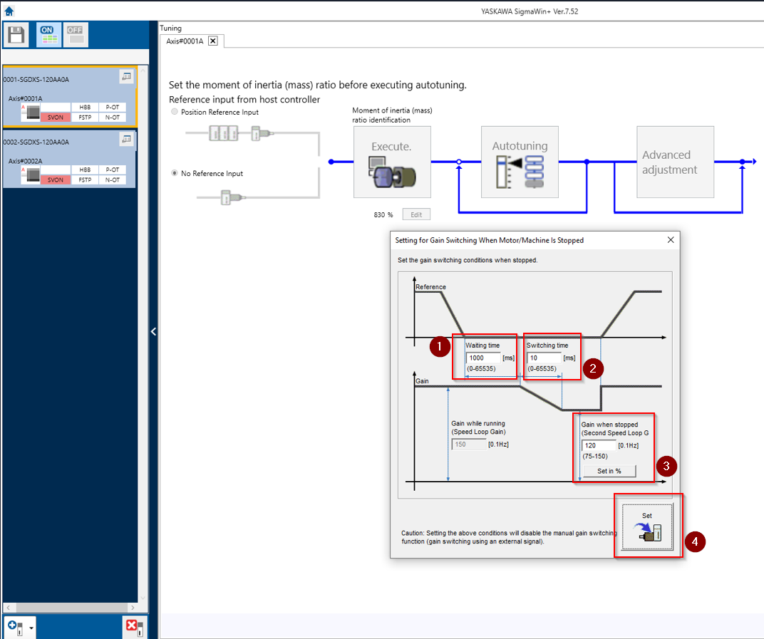
There are settings for the specific conditions of Automatic Gain Switching that can be accessed through Tuning>Advanced Adjustment>Gain Switching. This will bring you to the dialog below. There are 4 fields to input data into:
- "Waiting Time" dictates how long the condition of Pn139.1 must be true before the gain switching activates.
- "Switching Time" dictates how gradually the changes in between Gain Sets 1 and 2 ramp down. (This may need adjust if the process of switching gains causes a clunk or a hum)
- "Gain When Stopped" dictates a percentage of Gain Set 1 that will be applied to Gain set 2 when the switch happens. (Usually this is will be obsolete because Gain Set 2 will be manually changed to desirable values).
- "Set" will modify the Pn139.0 to value "2: Use Automatic Gain Switching" and adjust the value of Pn106 to be the percentage that you selected in field 3.
9103