Yaskawa Analog Monitor Output
Sigma 7 Pulse and Direction Drive
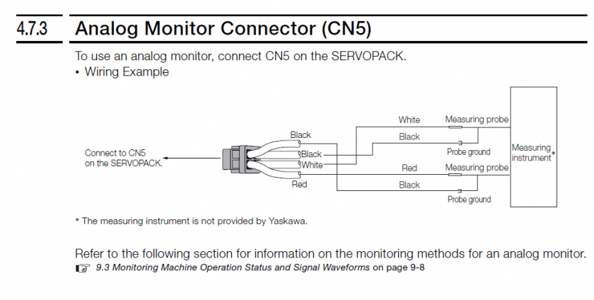
Wiring
Wire the analog input to the analog monitors on CN5.
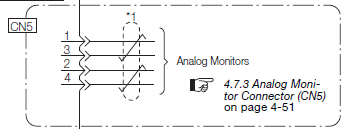
Use a cable as shown below:
Setup Options
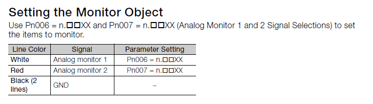

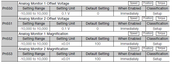
Factor and Offset
Load Meter
Analog Monitor 1
Pn006=.XX02

Calculate the value of Pn552 based on the max rated torque you will ever see on this device:
Pn552 = 10V / (0.01 * Max Rated Torque %)
| Max Rated Torque % | Pn552 |
| 40% | 25.00 |
| 50% | 20.00 |
| 100% | 10.00 |
| 300% | 03.33 |
For example, if you want to see up to 50% of rated torque, calculate it as follows:
Pn552 = 10V / (0.01 * 50%) = 20.00 so you would set Pn552 to 20.00.
Default for reg wheel on centerless grinders pn552 =100. Reg wheel torque is so low you will not see the load change unless on a machine.
Proof:
Actual Output Voltage = Pn552*0.01 * Actual Rated Torque %
Substitute Max Output Voltage for Actual Output Voltage and Max Torque for Actual Rated Torque:
Max Output Voltage = Pn552*0.01 * Max Rated Torque %
Solve for Pn552:
Pn552 = Max Output Voltage / (0.01 * Max Rated Torque %)
Set Max Output Voltage to 10V:
Pn552 = 10V / (0.01 * Max Rated Torque %)
Mach4 Setup
If using the Siemens PLC, see this document: Siemens PLC - Wiring SM1234.
Reference Manual: See attached Sigma-7 Manual Analog-Pulse.pdf
Keywords: Load meter, spindle load