Delta VFD MS300 Installation
![]()
 |
The MachMotion files for the Delta MS300 are located here: M:\Production\Products\Spindles\VFDs\Delta\MS300 The Users Manual and DCISOft.exe are attached to this bookstack. This is a helpful YouTube video on how to use the keypad on the Delta MS300 You can perform a factory reset of the Delta MS300 Step 1. First stop the motor if running. Step 2. Then press "enter" button and select "00" then press "enter" button. Step 3. After select "00" then press "enter" button again. Step 4. When display show "00.00" then press "UP" key two times then display show "00.02". Step 5. When display show "00.02" then press "enter" button and select "9" then press enter button. After this all parameters are set to factory default. |
Wiring
Apollo III: Please see installation process in the Appendix.
Control Cable
The VFD Control cable is the Ethernet cable (Green) that runs from the Delta VFD to the Control as shown in Figure 1 and Figure 2.

Figure 1 Ethernet Connection to VFD

Figure 2 Ethernet Connection to Control
Spindle Motor:
Connect your spindle motor to the terminals labeled U/T1,V/T2, and W/T3 as shown in Figure 4. If your spindle moves the wrong direction when you turn it on, just swap any three of the (U,V,W) leads.

Figure 3 Spindle Motor Connections
Brake Resistor
Connect your brake resistor by placing the two wires on the +2/B1 and B2 terminals as shown in figure 4.
(Note: If needed to extend the wires use High Temp rated wire.)
Mount Resistor
Mount the resistor to the cabinet.

Figure 4 Delta VFD MS300 Resistor Connections
Programming
Changing IP Address
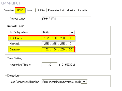
The IP address of the VFD must be set to 192.168.208.80 to communicate with Mach4. This has to be done on the drive. After communication with the drive is set up all other programming and modifying parameters can be done over the network from the MachMotion Parameters page in the MachMotion Plugin.
| Parameter | Desc | Value |
| 09-76 | IP address -1 | 192 |
| 09-77 | IP address -2 | 168 |
| 09-78 | IP address -3 | 208 |
| 09-79 | IP address -4 | 80 |
| 09-84 | Default gateway -1 | 192 |
|
09-85 |
Default gateway -2 | 168 |
|
09-86 |
Default gateway -3 | 208 |
|
09-87 |
Default gateway -4 | 80 |
You can also set the IP address with the DCISoft application that is attached to this document.
- Open the software and click on Tools | Communication Setting
- Change the type from RS232 to Ethernet and click OK. You may need to change the specific network controller.
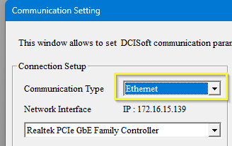
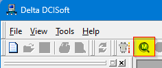
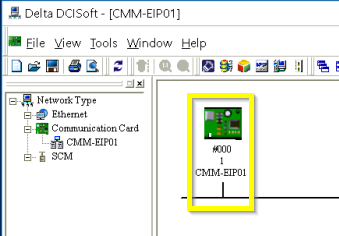
- Click the M icon to search for devices

- It should locate the ModBus card on the Delta drive and show its current configuration. If it does not have a valid IP address for the current network, it may take longer for the software to locate the card. You may also get several errors.

- Double click on the green ModBus card and it will come up with the Overview tab.
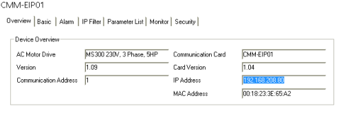
- Switch to the Basic tab to make changes to the IP address and Gateway.

- Set the IP address and the Gateway, then click the Apply button
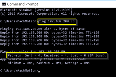
- Open a CMD terminal window and try pinging the card. If the ModBus card responds, click OK and close the software.


VFD Programming
To program the VFD you will need to utilize the Mach4 software. While the control is disabled follow the next few steps.
Step 1: Click on Configure -> Plugins -> MachMotion

Step 2: While in the MachMotion Plugin Type "Delta" in the search field.

Step 3: This will populate the Parameters for the Delta VFD MS300.

Please utilize these default parameters but you can always adjust these parameters based on the spindle motor. Be sure to scroll down to see more of the parameters.
Delta VFD MS300 Parameters
| Parameters | Description | Standard | Range | Delta Defults |
| 01-00 | Max Operation Frequency | 60 | 00.00~599.00 Hz | 60.0 / 50.0 |
| 01-01 | Base Output Frequency | 60 | 00.00~599.00 Hz | 60.0 / 50.0 |
| 01-02 | Max Output Voltage | 220 |
|
|
| 01-07 | Min. Output Frequency | 0 | 0.00~599.00 Hz. |
0.50 |
| 01-08 | Min. Output Voltage | 0 |
|
|
| 01-12 | Accel. Time | 5 | 0.00~600.00 sec. | 10 |
| 01-13 | Decel. Time | 5 | 0.00~600.00 sec. | 10 |
| 05-00 | Motor Parameter Auto Tuning | 0 |
|
0 |
| 05-01 | Full-Load Current of Induction Motor | 1 | 10~120 % of drive’s rated current | |
| 05-02 | Rated Power of Induction Motor | 1 | 0~655.35 kW | |
| 05-04 | Pole Number of Induction Motor | 4 | 2~20 | |
| 06-01 | Over-Voltage Stall Prevention | 0 |
0: Disabled Make sure to set this to zero if you are using a brake resistor. |
|
| 07-00 | Software Brake Level | 390 |
|
|
VFD - Spindle Calibration
All the instructions for spindle calibration can be found in VFD - Spindle Calibration
Appendix
Apollo III
If you have an Apollo III board you will need to connect the Ethernet cables in a specific way.
1. Install the communication card on the Delta VFD. Place the Black Connection harness to the communication card and place the green PE wire into the green connection.

2. Connect Ethernet cable coming from the Delta VFD to Ethernet 2 Port on the Apollo III.
3. Connect the Computer Ethernet cable to Ethernet 1 Port on the Apollo III.
4. Connect the the Apollo III board enable to Delta MS300 VFD as shown below.

5. Refer back to Step 1 for motor wiring and incoming power wiring.
Alarms
If you were to get an alarm on the VFD you will receive a message on the computer screen from the Global Message System. For example, the figure below shows a communication alarm. In the description of the alarm it will describe the necessary steps to try to resolve the alarm.

Warranty Information
MachMotion warranty policy is subject to change. Updated information is available at our website:
https://machmotion.com/warranty
The MachMotion Team
http://www.machmotion.com
14518 County Road 7240, Newburg, MO 65550
(573) 368-7399 • Fax (573) 341-2672