Stepper Drive Setup Guide
1 Overview
The MachMotion micro-stepping drive is used to control all different types of stepper motors. This document will give you all the information you need to connect your motors to your drives. The drives are wired using simple screw terminals as shown in the picture below.

Figure 1 Stepper Drive Overview
1.1 Connectors/Switches
The Configuration Switch allows you to easily configure the drive to your particular motor. For more information see the section titled Configuration Switch on.
The Control Connector should be wired up when you receive your stepper drive. Plug the other end of it into the MachMotion IO6 Breakout Board (Figure 3). Below is the pin-out of the prewired control cable.
|
Signal |
Color |
|
PUL+ |
Brown/White |
|
PUL- |
Brown |
|
DIR+ |
Green/White |
|
DIR- |
Green |
|
EN+ |
Blue |
|
EN- |
Blue/White |

Figure 2 Control Cable
Finally, the Power Connector is where you will wire up your motor. See the section Connecting Your Motors.
Below is a diagram showing the stepper drive and motor setup.

Note: Power is not supplied to the drive shown above.
Figure 3 Drive Connection Overview
1.2 Status LEDs
There are three status LEDs on your stepper drive. The top LED labeled Signal is active when step and direction pulses are entering the drive through the Control Connector. Any time you command the drive to move you should see this LED turn on.
The second LED labeled Fault will turn on if you have a drive fault. Repower the drive to reset the fault. The smallest LED on the bottom labeled Power shows if the stepper drive has power supplied to it.

Figure 4 Status LEDs
1.3 Specification
|
Item |
Specification |
|
Motor Type |
2 Phase 4, 6, & 8 Wire Motors |
|
Supply Voltage |
120 VAC (Absolute Max is 130VAC) |
|
Max Current |
6 Amps |
|
Dimensions |
170 mm x 66 mm x 92 mm (L x W x H) |
|
Status LEDs |
Signal, Fault, Power |
|
Temperature |
80 Degrees |
Table 1
Refer to the figure below for the stepper drive’s dimensions.
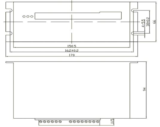
Figure 5 Drive Dimensions
Note: Mount your drives at least ¾ inch apart. The drives can generate a lot of heat so the correct spacing ensures proper cooling.
2 Finding Information
Before wiring up your drive, you must find the correct information for your stepper motor. You need to locate a diagram or schematic showing the coils’ configuration and the wire colors. An example diagram for a stepper motor is shown below. Notice that it shows how the coils are laid out and what wire each coil is connected to.
MOTOR EXAMPLE:

Figure 6 Example Motor Diagram
You also need to find the current rating for your motor. You may see the parallel and series current rating on the motor’s documentation. Only use the series current. If the document only supplies the parallel current, divide it in half. This gives you the correct current rating.
Now you are ready to get to work!
Note: If you are unable to find the current specification, you can experimentally find the current setting for the stepper drive. See Current Setting without Spec.
Note: For a 4 wire stepper motor, you can use a meter to find the coil configuration. If you find two wires with no resistance, you know you have one side of the coil. It doesn’t matter what side you found, as long as you have the correct two wires for each coil.
EXAMPLE:
Below is another stepper motor specification sheet.

Figure 7 Motor Specification
We need to know two different things about this motor.
- The Wire Colors and Coil Configuration
If you look carefully, the diagram showing the wire colors is on the bottom right hand side of this document. This is all the information we need to know about how to wire it up. - The Current Rating
In the specification table, there is a current value 3.5 A/Phase. This is all the information you need to configure your stepper dive.
3 Connecting Your Motors
3.1 For 8 Wire Motors Only
For eight lead motors, you must wire the coils together in series. The diagram below shows a normal eight lead motor. Connect the wires on your motor as shown by the red lines on the diagram.

Figure 8 Wiring Coils in Series
3.2 Connecting Your Motors to Your Drives
Now you are finally ready to connect your motors. Choose the two wires on the opposite side of each coil and wire them into the Power Connector (Figure 1). One coil combination will be A+ and A- and the other one will be B+ and B-. It does not matter which side of the coil is connected to the plus or negative terminals. Just make sure that the coils from different poles are not connected together. The Power Connector is shown below.

Figure 9 Power Connector
Note: No matter how many leads are on your motor, you will only connect
4 wires to the stepper drive!
See the following examples.
4 Wire Stepper Motor

6 Wire Stepper Motor

8 Wire Stepper Motor

Figure 10 Motor Wiring Examples
3.3 Supplying Power
Connect 120VAC to the bottom two pins of the Power Connector (Figure 1). Your stepper drive should now be completely wired up.

Figure 11 Power Connection
4 Configuration Switch
WARNING! This information only applies to the 6AMP model. For all information pertaining to the 8AMP please see this manual: KL11080
Newer stepper drives have 8 position DIP switches with different configuration than the 10 position DIP switches. Newer drives like the KL-2283 need to be added to this documentation.
4.1 Current Setting
The configuration switch is at the very top of the stepper drive.

Figure 12 Configuration Switch
If you found the current specification for your motor, use the following table to set the first 4 switches of the Configuration Switch.
Switch ON = 1, OFF = 0
|
Switches: 1234 |
Current |
Switches: 1234 |
Current |
|
1111 |
0.38A |
0111 |
3.38A |
|
1110 |
0.75A |
0110 |
3.75A |
|
1101 |
1.13A |
0101 |
4.13A |
|
1100 |
1.50A |
0100 |
4.50A |
|
1011 |
1.88A |
0011 |
4.88A |
|
1010 |
2.25A |
0010 |
5.25A |
|
1001 |
2.63A |
0001 |
5.63A |
|
1000 |
3.00A |
0000 |
6.00A |

For a motor supplied from MachMotion, use the following table to know what current setting should be used:
| Manufacturer Part Number | MachMotion Part Number | Series Connection Current | Motor Size | Current Setting |
| 60HS78DE076 | V00-MOT-0401 or V00-MOT-0401-C | 2.5 Amps / Phase | 370 oz/in | 1010 |
|
60HS100DE1
|
V00-MOT-0402 or V00-MOT-0402-C
|
2.5 Amps / Phase | 570 oz/in | 1010 |
| 90HS65DE053 | V00-MOT-0403 or V00-MOT-0403-C | 3.5 Amps / Phase | 600 oz/in | 0111 |
| 90HS78DE062 | V00-MOT-0404 or V00-MOT-0404-C | 3.5 Amps / Phase | 960 oz/in | 0111 |
| 90HS95DE052 | V00-MOT-0405 or V00-MOT-0405-C | 4 Amps / Phase | 1290 oz/in | 0110 |
| 90HS114DE065 | V00-MOT-0406 or V00-MOT-0406-C | 4 Amps / Phase | 1840 oz/in | 0110 |
| 90HS150DE082 | V00-MOT-0407 or V00-MOT-0407-C | 4 Amps / Phase | 2550 oz/in | |
| KL23H2100-50-8B | V00-MOT-0408 | 2.5 Amps / Phase | 570 oz/in | 1010 |
| KL42H2150-42-8A | V00-MOT-0409 | 3 Amps / Phase | 2830 oz/in | 1000 |
| KL34H295-43-8A | V00-MOT-0410-C | 3.05 Amps / Phase | 906 oz/in | 1000 |
Note: Always set the current setting to the same or lower value than the rated current.
4.2 Current Setting without Specification
However, if you could not find the current rating, follow the procedure below.
Note: Make sure your velocity and acceleration are very low before you begin.
- Set the Configuration Switch to 1111 (or a very low current rating).
- Jog your motor. If you lose position, increase the current setting. Continue to increase the current setting until your motor does not lose position. Record this value.
- Continue incrementing the current setting until you lose position again. Record this value.
- Find the average of those two settings. Set the Configuration Switch to this value. Your drive should now be configured correctly.
4.2 Defaults
The other switches 5-10 should always be setup the same way. They configure the current mode, the pulse type, and the microstep value. Make sure your drive matches the default switches as shown below.

Figure 5 Default Switches
5 Machine Units
Now you are ready to setup your machine units. Configuring your units makes sure that when you tell your control to move an inch, it actually moves an inch. If you are not using MachMotion motors, you must find the pulses per revolution (ppr) of your stepper motor. For all the MachMotion systems our motors are 200 ppr and the micro-step value on our stepper drives is set to 10. The micro-step acts like a step multiplier. Each step from the controller rotates the motor a specific number of steps defined by the micro-step number.
To setup your machine’s units, you must calculate the number of actual motor rotations per inch. After finding the motor rotations per inch, use the following formula to calculate the steps per inch:
EXAMPLE:
Assume you are installing one of the MachMotion Stepper kits on a machine with a 5 threads per inch (tpi) ball screw and a 2 to 1 gear reduction. Five tpi times the gear box reduction (2) gives us 10 motor rotations per inch.
Therefore, your steps per inch are:
Open up the Mach3 software. On the menu bar select Config->Motor Tuning. Then select the correct axis by pressing one of the axis buttons under the right column titled Axis Selection. Enter in your new steps per inch value in the bottom left corner. Then press SAVE AXIS SETTINGS. Press OK to end.

Figure 14 Steps Per Inch
6 Software Configuration
6.1 Velocity
Setup your velocity by clicking Config on the main menu bar, then Motor Tuning. You should see the following window.
Figure 15 Motor Tuning Setup Window
On the right of the Motor Tuning and Setup window it lists all the different axes. Click on the axis you want to setup.
Next enter in a low value for the velocity near the bottom left side of the window. Press SAVE AXIS SETTINGS for your changes to be implemented. Try to move the axis. If your stepper motor loses position, make sure that the acceleration is low enough. Slowly increase the velocity until you find you are losing position. Back down a little bit and use that value as your final velocity.
6.2 Acceleration Velocity
Setup your acceleration by clicking Config on the main menu bar, then Motor Tuning. You should see the Motor Tuning Setup window as shown in Figure 15. On the right of the window it lists all the different axes. Click on the axis you want to setup.
Start the acceleration at 5. Make sure to press SAVE AXIS SETTINGS. Slowly increase the acceleration until you lose position. Back down a little bit and use that value as your final acceleration.
7 Appendix
Warranty Information
MachMotion warranty policy is subject to change. Updated information is available at our website:
https://machmotion.com/warranty
The MachMotion Team
http://www.machmotion.com
14518 County Road 7240, Newburg, MO 65550
(573) 368-7399 • Fax (573) 341-2672