Yaskawa Absolute Encoders with Apollo III
Yaskawa Absolute Encoder feature allows the Apollo III to read the encoder position without the need for homing. When the CNC control software starts the software will read the encoder positions from the servo drives and update the internal positions from 0 to the actual motor positions.
Absolute Encoder Overview: https://youtu.be/nGCJj8cYBUA
Setup of Encoder: https://youtu.be/KQ_Kn0_gT4k
Requirements:
-
X15-03-04-1.02 ABS Encoder Board Assembly
-
CCY-DF with X15-02-09-1.08 Yaskawa CN1 Digital Drive Adaptor (Needs to be Reversion 1.08) with jumper installed on J5 and in the 2 and 3 position. DO NOT SHIP JUST X15-02-09-1.08... must be CCY-DF. Included by default currently.
-
JZSP-CSP12-E ABS ENC EXTN Cbl W/BAT 0.3M (Battery adapter not needed for battery less absolute encoders, or Dual Loop scales)
-
100536 Hex6.35x17.46 Standoff for Apollo III board
-
150063 6-32 1/4" SS-PAN-PH
-
100412 Apollo III Absolute Encoder license
Components:
Absolute Encoder License
Use the VSI Device Manager to confirm the Absolute Encoders feature is active. Or you need to purchase it and the software license part number is ABS-57.

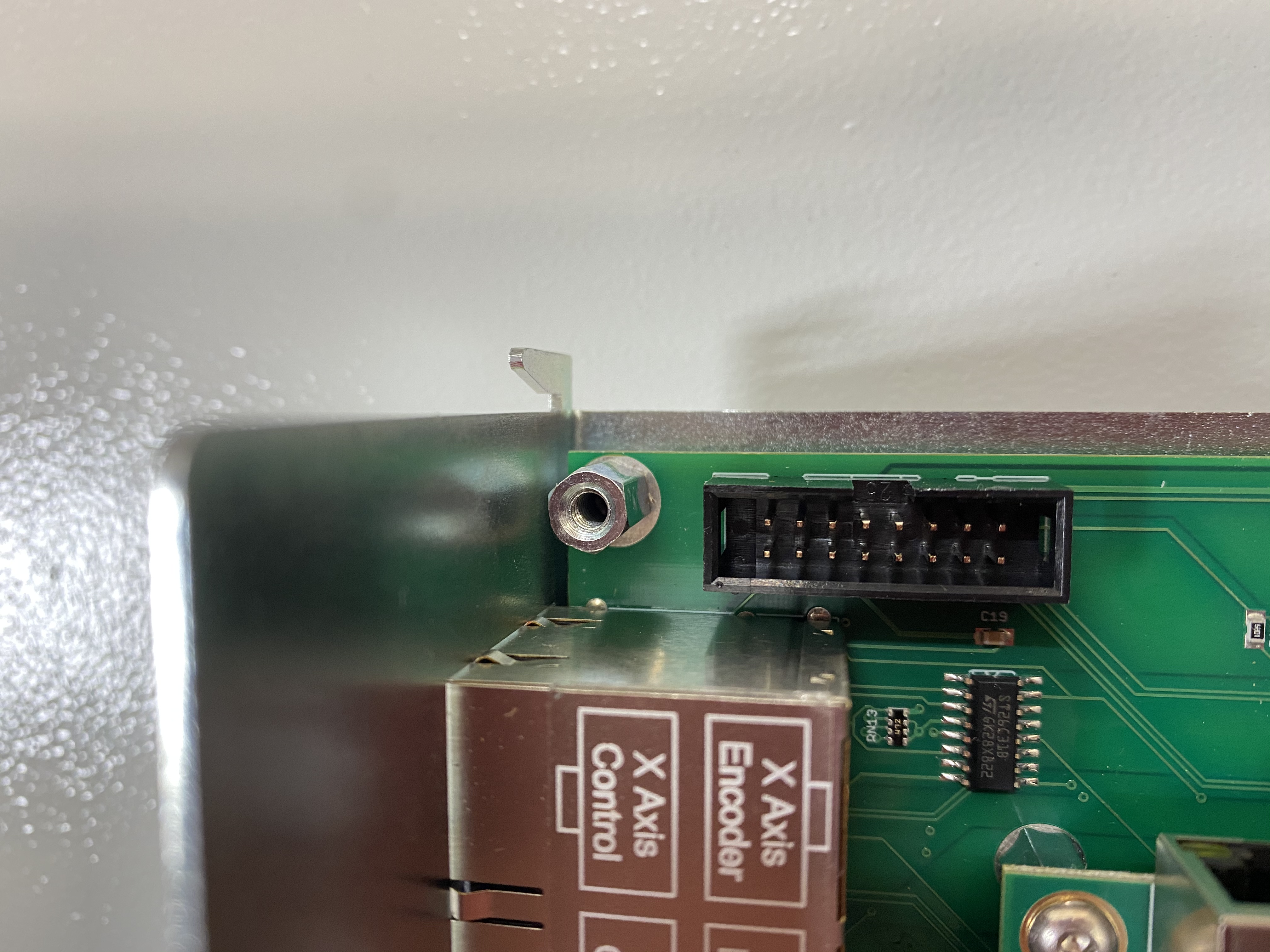
Buffer board X15-03-04
This board is used to send the SEN command to the Yaskawa servo drive through the Servo Adaptor Board. The board needs to be installed onto the Apollo III and a wire ran from the terminal labeled "1" on the green block to J1 pin "5" of the Servo Adaptor Board.

Digital Servo Adaptor board CCY-DF
This board is used to connect the Yaskawa drive to the Apollo III for commands and feedback. Confirm the version number on the board is at least V1.08 or it will not work with the Absolute Encoder interface.

Motor Encoder Cable with Battery JZSP-CSP12-E or External Absolute Encoder
Yaskawa servo motors need a battery on the encoder cable to use the Absolute Encoder feature. A new encoder cable can be purchased with the battery installed or a adaptor can be used like the one in the following photo.
(Not needed for battery less absolute encoders, or Dual Loop scales)

Installation
Hardware Kit
- Buffer board part number X15-03-04
- Digital Servo Adaptor board part number X15-02-09 with jumper installed
- Motor Encoder cable with batter or battery adaptor JZSP-CSP12-E
- Standoff MPN number Hex6.35x17.46 and MM number 100536
Remove cover

Remove mounting screw

Install Standoff
Install Buffer Board

Reinstall mounting screw

Install jumper on servo adaptor J5 pin 2-3 next to the labeled SEN

Install wire from Buffer Board to all Yaskawa servo adaptors for SEN signal

Install Motor Encoder Cable with Battery (Not needed for external absolute encoder)
(Unless battery less absolute encoders, or Dual Loop scales)
Software and Parameters Setup
Yaskawa Servo Drive
Servo Drive Parameters:
We need Pn002.2 set to 0 (Factory setting). This will enable the SEN input to be used to send the encoder position to the motion controller. You can do this inside the programming software or directly on the face of the drive.


If you are using a Dual Loop absolute encoder (like the HEIDENHAIN LC415 or ROQ 437) Skip down to the Software Setup section
Servo Drive Absolute Encoder Reset
The rotational data will be a value between -2 and +2 rotations when the absolute encoder setup is executed. The reference position of the machine system will change. Set the reference position of the host controller to the position after setup.
If the machine is started without adjusting the position of the host controller, unexpected operation may
cause injury or damage to the machine. Take sufficient care when operating the machine.
Setting up the absolute encoder is necessary in the following cases:
- When starting the machine for the first time
- When an encoder backup error alarm (A.810) is generated
- When an encoder checksum error alarm (A.820) is generated
- When initializing the rotational serial data of the absolute encoder
You can do this inside the programming software or directly on the face of the drive.
Programming Software
After enabling absolute encoder, software reset, disconnect and reconnect to the drive. Then the Reset Absolute Encoder function should be enabled. Then do a Software Reset again and you should be good to go.

Face of the drive
Set up the absolute encoder with Fn008.
Precautions on Setup
- Set up the encoder when the servo ON signal (/S-ON) is OFF.
- If the following absolute encoder alarms are displayed, cancel them with this Fn008 process. They cannot be canceled with the SERVOPACK alarm reset input signal (/ALM-RST). Note that using Fn008 will reset the zero on the axis. This is not as accurate as the method detailed in Software Setup below, but it may be sufficient for the customer's needs.
- Encoder backup error alarm (A.810)
- Encoder checksum error alarm (A.820)
- Any other alarms (A.8xx) that monitor the inside of the encoder should be canceled by turning OFF the
power.
Procedure for Setup
Follow the steps below to setup the absolute encoder.

Read Encoder Output Pulse Parameter
If using Fully-closed Loop Control with Endat 22 External Absolute Encoder use 1048576 for the Encoder Counts Per Rev xx in the MachMotion plugin and skip this section.
Only use this calculation for a motor encoder - not used for fully closed loop.
Read the number of encoder pulses per revolution in parameter Pn212. Now we need to multiply the encoder pulses by 4 to convert them to encoder counts.
Example:
Encoder Pulses: Pn212 = 4096
Encoder Counts: 16384 = 4096 * 4
Now we can enter the calculated value into the Control parameter "Encoder Counts Per Rev Motor x" under the Absolute Encoders section.
If your position changes when restarting Mach4, it's because your Encoder Counts Per Rev XX is not calculated correctly.
Software Setup
- Absolute Encoders HiCON Enabled = Yes
Configure the following parameters for each motor that will use Absolute Encoders. If you enable Absolute Encoders in Mach for a motor but haven't enabled it yet in the drive, you will get errors.
- Absolute Encoders Enabled Motor xx = Yes
- Encoder Counts Per Rev Motor xx = Encoder Counts calculated in the section Read Encoder Output Pulse Parameter
- Origin Offset Counts Motor xx = Optional, offset the absolute value read from the drive. Units are Encoder Counts. This will be more accurate than resetting zero with FN08. Some customers need this accuracy and some do not.
- Set the Origin Offset Counts Motor XX parameter to zero for this axis
- Set the motor to the correct homing method.
- Move the axis to where the zero should be.
- Home the axis. You may have to turn off the absolute encoder under the MachMotion plugin so it will allow you to home. After homing, re-enable the absolute encoder and then proceed.
- Compile Scripts, or restart Mach4 (the position will now read something other than 0.00)
- Read the encoder counts in the HiCON diagnostics
- Right click>Select all>Copy and paste that the encoder counts into this field in the MachMotion Control parameters.
- Do this for each axis with an absolute encoder.

If your system is using a HiCON motion controller, also enable Absolute Encoders for the HiCON:

Testing
Restart the CNC Control software and when the software loads it should read the encoder positions from the Servo Drives and mark each axis as Homed. When the Control software is disabled and you press "Reset" the control will update the encoder positions again. Another option is to press Compile Scrips to read the encoder positions.
Syncing Slave Motor Positions
When using ABS encoders on a axis with multiple motors caution needs to be taken to sync the motor positions before enabling or commanding any motion.
Squaring the Axis
Manually position the motors, ball screws or pinions so the axis is square and not mechanically binding.
Reset the ABS Encoder Positions in the Drive
Repeat steps Set up the absolute encoder with Fn008 to make sure the encoder is as close to zero as possible. When you run this function in the drive the encoder will not necessarily get set to zero.
Check Encoder Positions
All the Encoder positions need to match all the motors mapped to the slaved axis. To check the Encoder Positions open the HiCON status window. From the top menu select Diagnostic -> HiCON to open the HiCON Status window.

Compare the Encoder positions from all the motors mapped to the axis and find the difference between the master motor encoder and the slave motor encoder. If the motor encoder positions match then all motors are synced and ready for motion.

Sync Encoder Positions
Find the first slave motor and enter the difference between the master motor encoder counts and the slave motor encoder counts into the Origin Offset Counts Motor xx. When the HiCON reads the encoder positions from the drive it will apply these offsets to each motor.
Now we need to repeat the Check Encoder Positions and confirm that all the positions match. If they don't match then we might need to check the sign of the encoder counts we entered into Origin Offset Counts Motor xx. Sometimes changing the value to negative will fix this problem.
Troubleshooting
Overview Video for Troubleshooting: https://youtu.be/zZmlGhWAGVU .
If you get a following error, confirm you have servo lock. If you don't have servo lock, confirm you have enabled absolute encoders on the Apollo III (not motor specific, but system wide):
- Absolute Encoders HiCON Enabled = Yes
If that is enabled but it's not reading in the encoder position, you should be getting an error like this:

If you have the Error In Motion Controller Initialization, it means there is an issue with the SEN wiring or the buffer board. Confirm that SEN signal was wired up on your machine.
If the drive shows ". . bb" then there is a problem with the SEN signal not connected to the drive.
You can jumper out SEN to 5V on the Apollo III motion controller and confirm it shows up in the drive monitor software. With 5V connected it should be ON.

Other troubleshooting ideas
- Disable all but 1 absolute encoder and test it.
- Switch to another absolute encoder and confirm both do not work.
Keywords: X15-03-04-1.02