CTB MAS D3 Servo Drives
![]()
Introduction
MachMotion offers two series the GH single axis and MAS multi axis drives. The GH can be used as a single axis servo drive and can be connected to a range of PM motors or can be used to drive a AC induction spindle motor. The MAS come in to versions 3 and 4 axis.
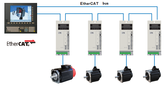
The drives all use EtherCAT for communication from the drive and controller.
Parameters
Modifying and reading parameters on the drive
On the front panel of the drive there are the following buttons

The multi axis drives parameters split up for each axis Ch--1, Ch- -2, and Ch- -3 each channel corresponding to motor 1, motor 2 and motor 3. Under each channel there are multiple parameter groups
Anytime a parameter in this manual has the letter "x" its to indicate the motor channel number.
Disable Motor Encoder Alarm EL (Ex)
Use the Up and Down arrows to select the axis channel (Ch--1, Ch- -2, and Ch- -3) you want to disable. Press Enter and then use the Menu button to cycle though the parameter groups until you get to --Px-, press Enter to enter the Px group and then use the Up and Down arrows to select Px-03. Press Enter to view the current value of the parameter and then press Enter again to edit. Use the Up arrow to set it to 1 and then press Enter. Press Reset to clear the alarm.
You can also do this through the Rapidpath plugin and write the parameter directly to the drive.
ABS Encoder
To ensure that the CTB drive will not allow encoder alarms to be cleaned via EtherCAT set the following parameters to 0: (testing shows this needs to be set to 1 - 10.15.25 - test more to confirm.)
| Parameter | Name | Description |
| Px-03 | ignore encoder alarms |
bit 0: ignore EL alarm bit 1: ignore EC alarm bit 2: ignore EP alarm bit 3: ignore ES alarm |
Wiring
GH Series
Wiring overview
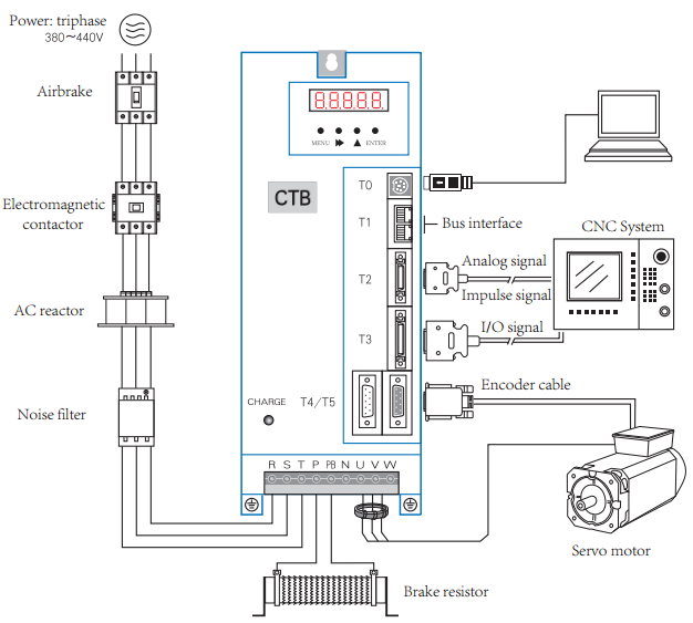
Wiring logic overview
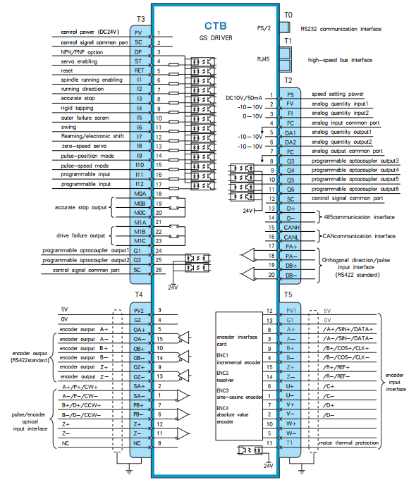
EtherCAT buss (Connectors T1 and T2)
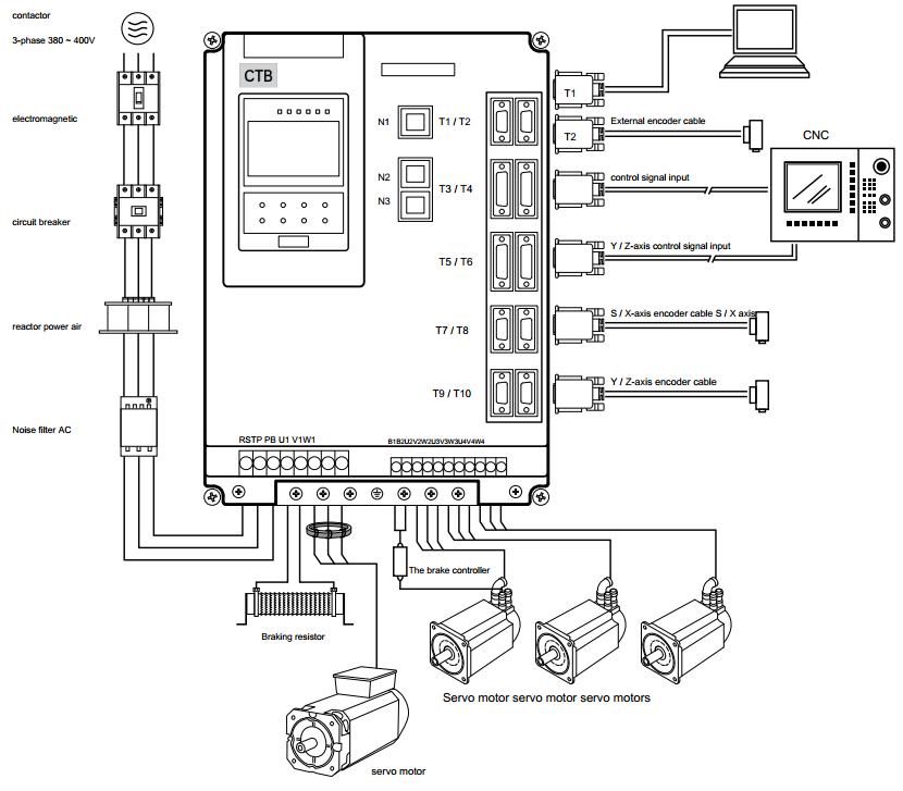
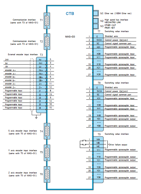
MAS Series Version D3
Spindle Setup
The CTB drives can be configured to use the encoder on that is built into the motor or a external load encoder for position feedback. The encoder on the motor should always be connected to the drive with connector T5. You can view the position of the main encoder with U2-00. Every spindle drive is expected to have the correct braking resistor installed.
Spindle Configurations
- V belt spindle drive with external encoder connected to CNC control. The CNC control can monitor the encoder and control the drive in speed mode.
Supported Functions: Speed mode, threading.
- Synchronous belt transmission, the transmission ratio of 1:1, with zero position switch.
Supported Functions: Speed mode, spindle orientation, C axis positioning, threading, rigid tapping.
- Synchronous belt transmission, the transmission ratio of 1:1.
Supported Functions: Speed mode, spindle orientation, C axis positioning, threading, rigid tapping.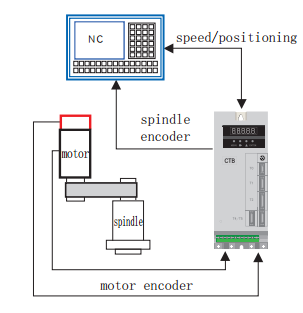
- Gear box with multiple transmission ratios, external encoder mounted 1:1 ratio to the spindle.
Supported Functions: Speed mode, spindle orientation, C axis positioning, threading, rigid tapping.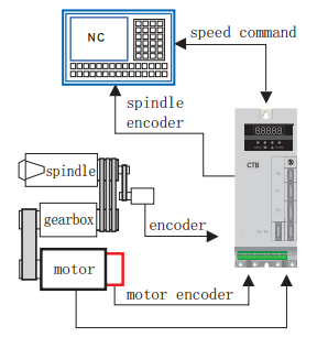
External Load Encoder
The external encoder must be a 5V TTL quadrature encoder with A,B and marker pulse to be used for orientation of the spindle. It is very important that the external encoder is mounted 1:1 ratio to the spindle load.
- Encoder wiring:
Function Cannon Plug DB15 Pin Number 0V K 4 5V H 3 A A 2 /A N 1 B C 7 /B R 6 Z B 12 /Z P 11 Shield Shell - Encoder parameters:
To use the external encoder set C1-03 = 1 and C1-04 = 2. To view the external encoder count on the drive look at U2-01.Parameter Name Descriptions Factory Setting C1-03 Position Feedback Source 0: Motor Encoder (T5)
1: External Encoder (T4)
0 C1-04 Position Operation Source 0: Invalid
1: Motor Encoder (T5)
2: External Encoder (T4)
1 E1-15 External Encoder Type (T4) 0: Invalid
1: Quadrature
1 E1-16 External Encoder Pules Count (T4) 0~16348 1024 E1-17 External Encoder Direction (T4) 0: Clockwise
1: Counterclockwise
0 E1-18
External Encoder Reduction Ratio Numerator (T4) 1~30000
1 E1-19
External Encoder Reduction Ratio Denominator (T4) 1~30000
1
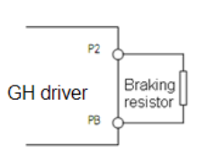
Brake Resistor
- Connection of braking resistor
The P, PB terminals on main circuit block of AC servo driver are for connection with braking resistor.
Please do not connect braking resistor to other terminals, otherwise, the braking resistor will heat up and
burn out, or cause damage to the driver.
Specification of braking resistor
BKSC-XXXX GHX 43
P745
P547
P540
1140
1540
1840
2240
3040
3740
4540
5540
7540
9041
1041
3241
6042
0042
50
43
15
Power
W60
080
010
0060
080
010
0010
0015
0020
0020
0025
0025
0025
0025
0020
0020
0025
0025
00
25
00
Resist
ance
Ω50 40 32 50 40 32 32 32 20 20 20 20 20 20 20 20 20 20 20 Qty. 1 1 1 2 2 2 2 2 2 2 2 3 3 3 4 4 6 6 8 - Parameters setting
Set the following parameters
Parameter Name Descriptions Factory Setting P1-01 Buss Over Voltage Alarm 0~10000
800
Firmware
Updating MAS Firmware
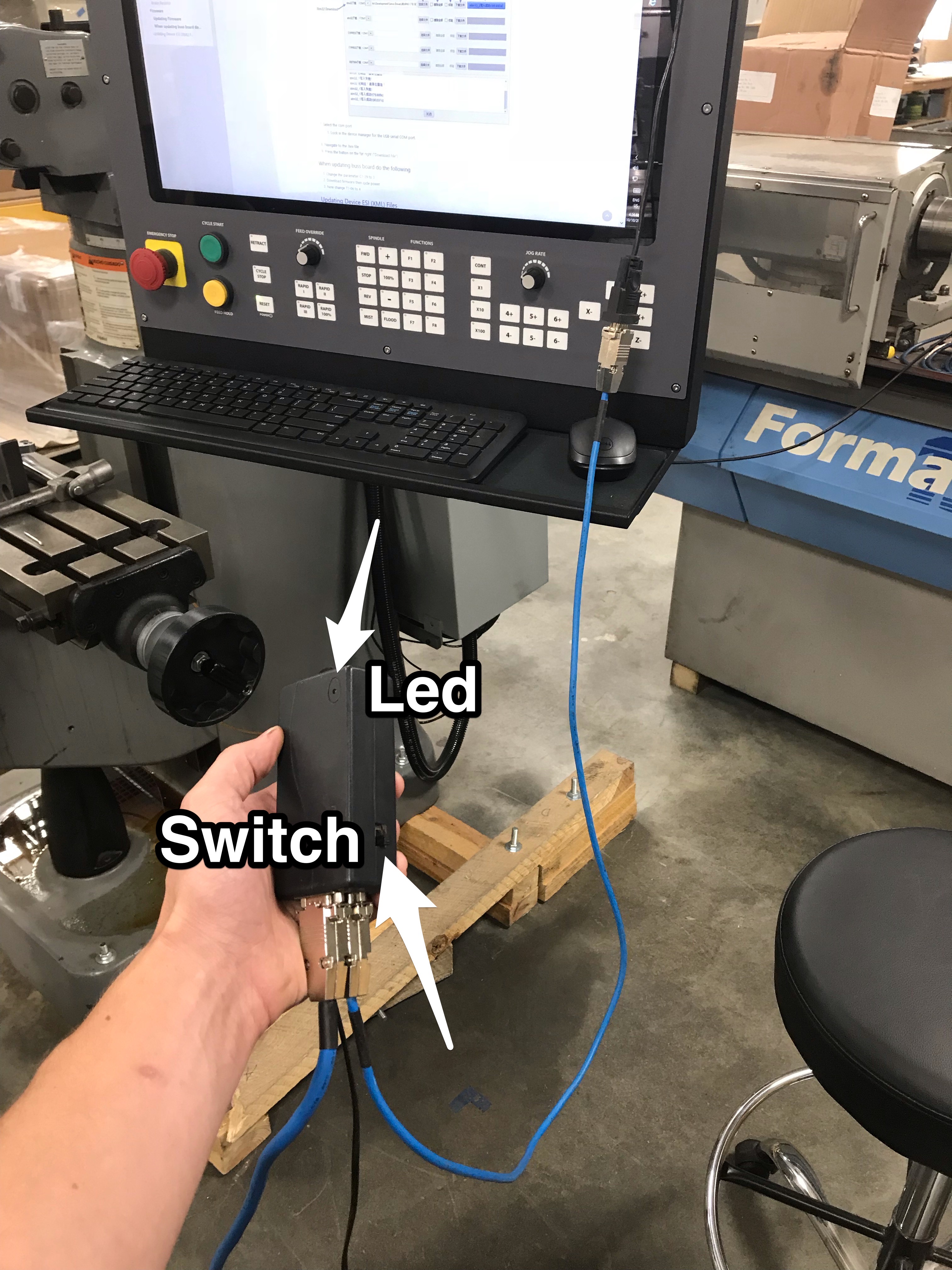
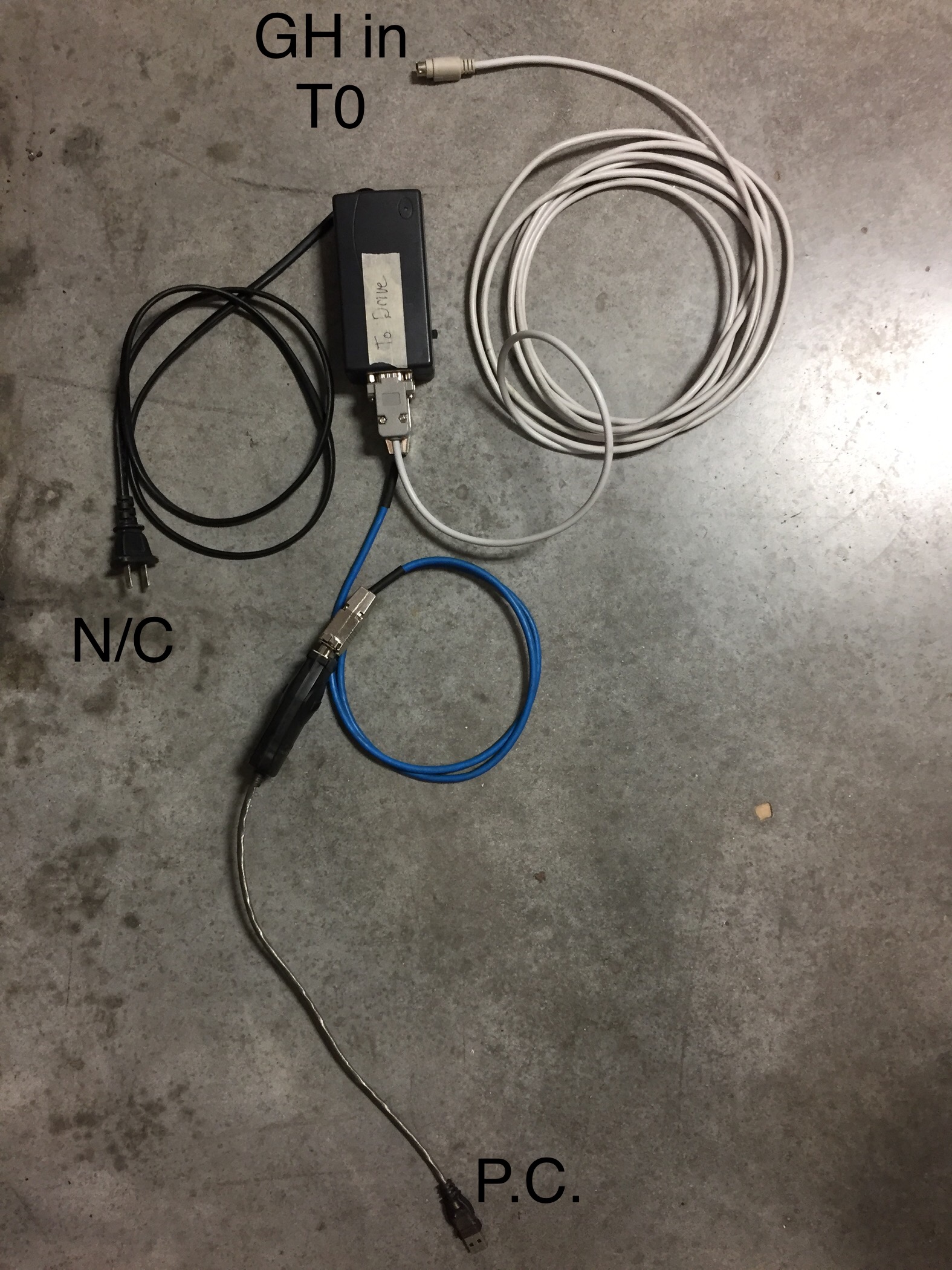
- Power off the drive
- Slide the switch on the black programmer towards the LED
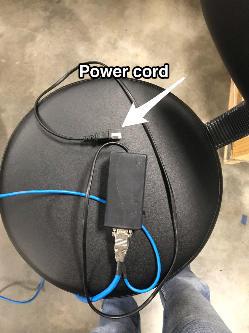
- Plug the RS232 cable from the programmer into a USB to Serial adapter and connect the USB to the control

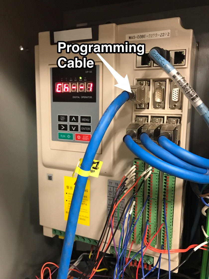
- Connect the larger blue programming cable to the drive
- Plug the programmer power cord into a 115V outlet and leave the main power to the drive off
- Make sure the LED on the programmer is solid red
- Download from this document the attached "STMicroelectronics flash loader.zip" and the "GH and MASD3 Firmware M_xxxxxx.zip"
- Unzip the downloaded files
- Open this programmer application (STMicroelectronics flash loader.exe)
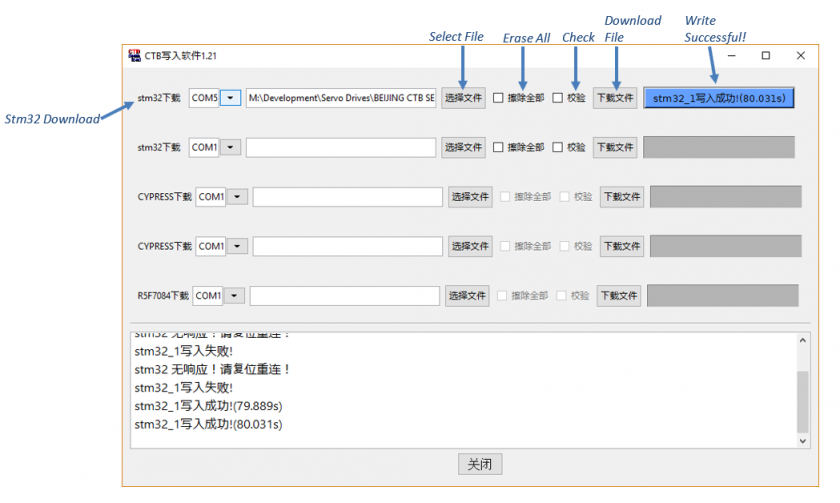
- Select the com port
- Look in the device manager for the USB-serial COM port.
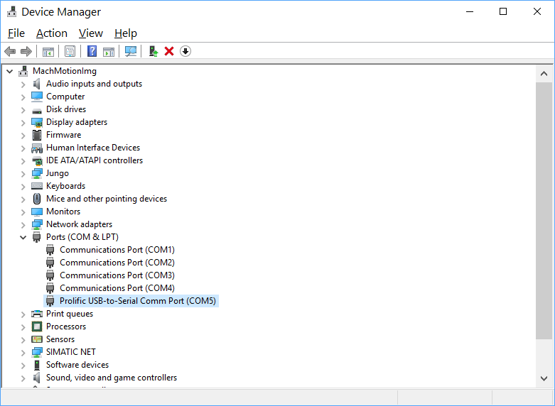
- Look in the device manager for the USB-serial COM port.
- Navigate to the .hex file file that was in "GH and MASD3 Firmware M_xxxxxx.zip" folder
- Select the appropriate file (GHB5_StandardExxxxxx) or MASD3_407_USA_MACHMOTION_20181115.hex)
- Check the first checkbox ('Erase All')
- Press the button on the far right (“Download File”)
- Wait for the progress bar to complete. If the programmer has any errors unplug the programmer power cord and try again.


Updating GH Firmware
Use this programming cable.
Download small cpu way for GH:
1. L1-12 set 200
2.restart downloader(green )
3.then the GH screen show "don-1" ,use the soft"STMicroelectronics flash loader.exe" download.
Download parameters for the MASD3 drive:
- Set parameter L1-12 to 101
- Press 'Menu' until L1 shows on screen
- Press 'Enter'
- Press the up arrow until L1-12 shows on screen
- Press 'Enter' twice
- Press 'up', 'right', 'right', 'up'
- Screen should show 101
- Press 'Enter'
- Remove power to drive
- Switch downloader to green LED
- Plug cable back into drive
- LED screen will flash 'cTb', then show 'don-1'
- In the flash loader program, select the MASD3_103_USA_MACHMOTION_20172711.hex file and download
- Cycle power to the drive
- LED screen will flash 'cTb', then show 'don-2'
- Download the MASD3_103_USA_MACHMOTION_20172711.hex file
- Cycle power to the drive
- LED screen will flash 'cTb', then show 'don-3'
- Download the MASD3_103_USA_MACHMOTION_20172711.hex file
- Cycle power to the drive
- LED screen will flash 'cTb', then show 'E1.EL'
When updating buss board do the following (Currently not used)
- Change the parameter C1-29 to 3
- Download firmware then cycle power
- Now change T1-06 to 4
Updating Device ESI (XML) Files
- Download from this document the attached "EtherCAT_Configurator.zip"
- Unzip and install the "EtherCAT Configurator.exe"
- Download from this document the attached "GH and MASD3 ESI XML Files.zip"
- Unzip the "GH and MASD3 ESI XML Files.zip" and copy the files to "C:\Program Files (x86)\EtherCAT Configurator\EtherCAT\"
- Connect the EtherCAT network CAT5 to the Machine Network port on the CNC control.
- Open the EtherCAT Configurator Program

-
Left Click On "Evaluate (Button)"

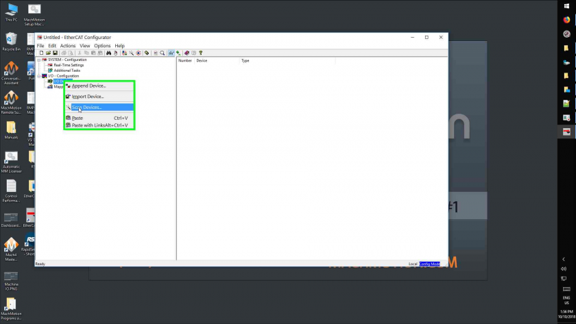
If the "Evaluate" button is disabled, you can find registration information in RoboForm. - Right Click On "I/O Devices (Tree Item)"
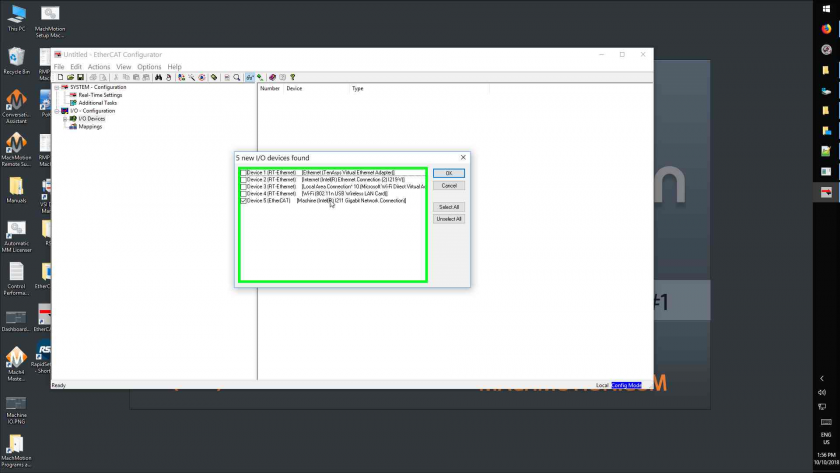
- Left Click On "Scan Devices... (Menu Item)"
- Left Click On "Ok (Button)"
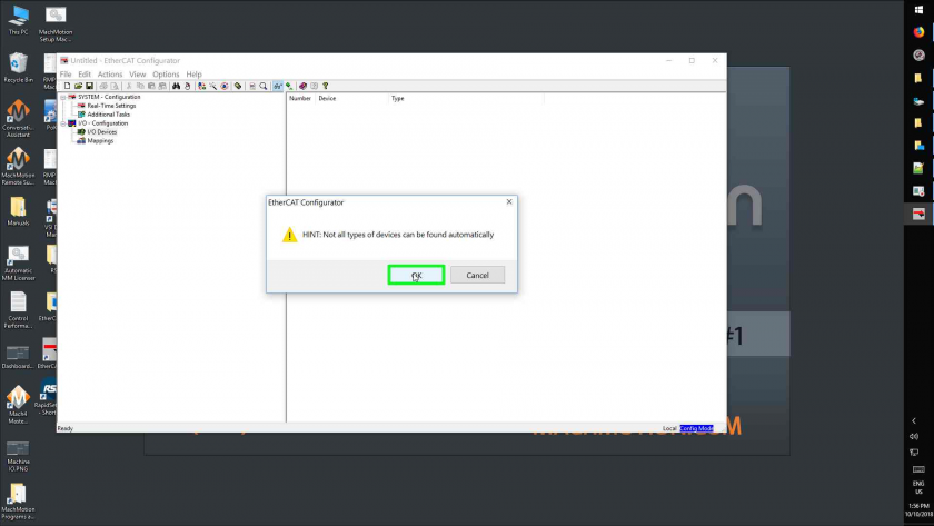
- Select all devices and click 'OK'
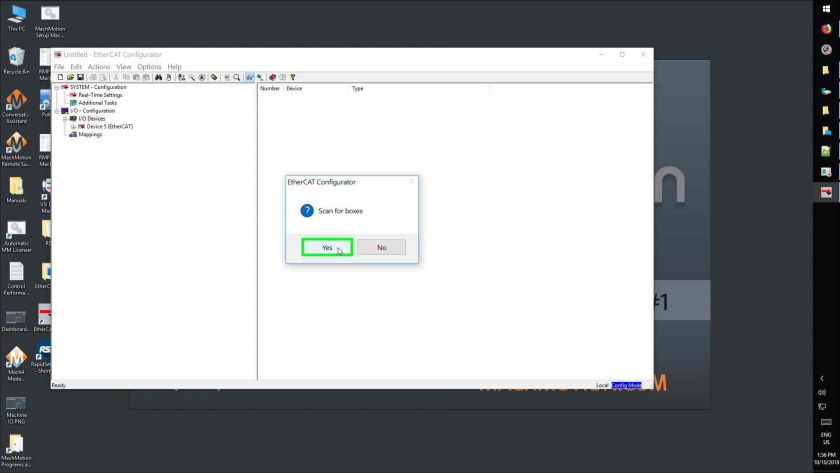
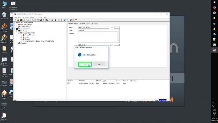
- Left Click On "Yes" for 'Scan for Boxes' and then 'Activate Free Run'
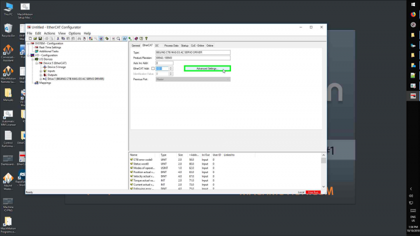
- Left Click On "Drive 1 (Beijing Ctb Mas-D3 Ac Servo Driver), then "Ethercat (Tab Item)"
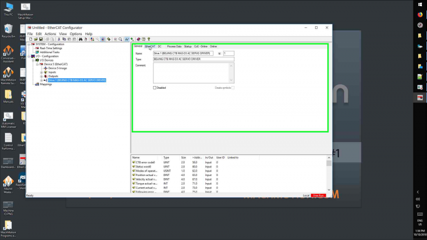
- Left Click On "Advanced Settings... (Button)"
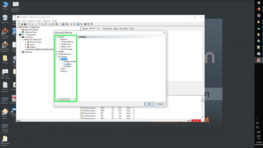
- Left Click On "Smart View (Tree Item)"
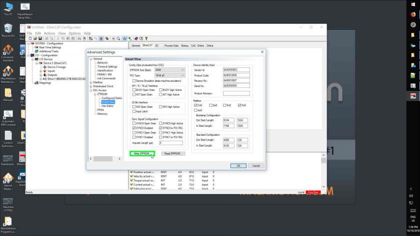
- Left Click On "Write E²prom... (Button)"
- Left Click On "Beijing Ctb Mas-D3 Ac Servo Driver (65542 / 65543) (Tree Item)", then click 'OK'
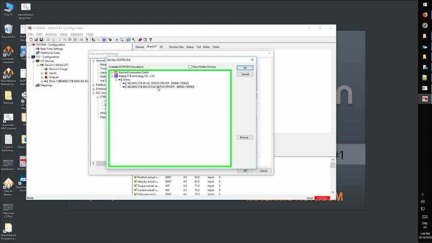
- Left Click On "Ok (Button)" to close the "Advanced Settings"
- Close program
- Do not save changes if prompted
Programming Parameters
- Acquire MH1000(e) executable
- Run it
- If you get an error, change your COM port
- Select 'File', 'Open', then select the parameter file for the drive
- 'MAS D3 Parameters 12-03-18.hc3'
- Select the filename that's now in the top menu and select 'DownLoad'

- For each error, press 'Ignore'
- After getting to 100%, press the chinese 'OK' button
- If there were errors, run 'DownLoad' a second time
- Close the software
Checking Firmware Versions
For the MAS-D3 drive, there are two parameters to check. The parameters should match the numbers at the end of their firmware filename. Parameters can be read through the screen or the MH1000(e) software.
- A1-08: Indicates firmware version on secondary CPUs. It is unknown what this parameter will display if not all of the secondary CPUs match in firmware.
- A1-09: Indicates firmware version on main CPU.
Troubleshooting
Jogging
To jog a motor, use the following procedure:
- Modify parameters Cn-29=1, Cn-30=0
- Under the F 0.00 menu, press the ENT key on the panel to enter the numerical input state, then use the ^ > key on the panel to input the speed to be operated, and press ENT key again, and then press >key, the motor starts to run.
- Press the key again to slow down and stop the motor.
When you're done, make sure to set Cn-29 back to 3 for ethercat communication or Rapidpath will not connect to the drive at all.
Motor Labeling
The multi axis drives parameters split up for each axis Ch--1, Ch- -2, and Ch- -3 each channel corresponding to motor 1, motor 2 and motor 3. Under each channel there are multiple parameter groups
Anytime a parameter in this manual has the letter "x" its to indicate the motor channel number.
Disable Motor Encoder Alarm EL (Ex)
Use the Up and Down arrows to select the axis channel (Ch--1, Ch- -2, and Ch- -3) you want to disable. Press Enter and then use the Menu button to cycle though the parameter groups until you get to --Px-, press Enter to enter the Px group and then use the Up and Down arrows to select Px-03. Press Enter to view the current value of the parameter and then press Enter again to edit. Use the Up arrow to set it to 1 and then press Enter. Press Reset to clear the alarm.
You can also do this through the Rapidpath plugin and write the parameter directly to the drive.
Alarms
E1 = motor 1, E2 = motor 2, E3 = motor 3
| E1.OC Over Current |
Major loop 316J detected serious over current through IO point to CPU. The Alarm cannot be reset and needs the power cycled. Turn the power supply to the servo drive OFF and ON again. If the alarm still occurs, the cause may be noise. | Power off to test drive module - Check motor parameter setting - Observe current during operation (A1-00 or U1-03) |
|---|---|---|
| E1.0V1 Over Voltage |
Alarm when the bus voltage is detected over the upper limit threshold (P1-01) | Check brake resistance whether can be suitable or not - Reduce acceleration and deceleration - Check incoming line RST AC voltage - Observe bus voltage value(U1-00 or U1-05) |
| E1.UV1 Under Voltage |
Alarm when the bus voltage is detected exceeding the lower limit threshold | Check incoming line RST AC voltage - Observe bus voltage value(U1-00 or U1-05) |
| E1.OH1 Module Overheating |
Temperature module AD test, alarm occurs if actual temperature is higher than 90C | Observe current during operation (A1-00 or U1-03) - Observe actual module temperature(U2-09) |
| E1.OH3 Motor Overheating |
Provide input point status judgment through motor internal thermal switch | Check motor fan - Check motor overheating alarm parameter (P1-05), any setting error of normal close - Set P1.05=2 to block the alarm |
| E1.EE2 Base EE Read Failure |
Alarm inspection for only one time after power on read power code from driver EE and alarm if the power code is not in driver power code table. The Alarm cannot be reset and needs the power cycled. | Set through power code parameter (L1-01) |
| E1.OC4 Over Current |
Alarm by the current comparator on the main board. The Alarm cannot be reset and needs the power cycled. | Power off to test drive module - Check motor parameter setting - Observe current during operation (A1-00 or U1-03) - Set P1.14=1 to block the alarm |
| E1.OL2 Overload |
Alarm occurs if actual motor speed lower than low speed overload threshold (P1.25) and actual current beyond the current which is calculated by low speed overload rate (P1.27) detect and exceed low speed overload time (P1.26). | Check if overloading time is too small - Check motor parameters - Observe current during operation (A1-00 or U1-03) - Set P1.25, P1.26, P1.27 to 0 to block the alarm |
| E1.CPU Small CPU Fault |
Determine through inspecting heartbeat of the small cpu. Alarm if it lasts for 50ms and disappear and it may be reset | Check version of the small CPU (A1-08) |
| E1.CO Communication Error |
Alarm for abnormal communication between the big and small CPUs, and it may be reset | Check version of the small CPU (A1-08) |
| E1.OC1 Over Current |
Effective current of motor is higher than 1.3 times of alarm current and lower than 1.5 times of it. This state lasts for 60 minutes and alarm. It can reset. | Check that the driving current alarm point (D1-12) is appropriate - Check motor parameters - Observe current during operation (A1-00 or U1-03) |
| E1.OC2 Over Current |
Effective current of motor is higher than 1.5 times of alarm current and lower than 1.6 times of it. This state lasts for 15 minutes and alarm. It can be reset. -Effective current of motor is higher than 1.6 times of alarm current and lower than 1.7 times of it. This state lasts for 7.5 minutes and alarm. It can be reset. -The effective current of the motor is higher than 1.7 times of the set alarm point current and lower than 1.8 times of the set alarm point current. The state lasts for 5 minutes and alarm. It can be reset. -The effective current of the motor is higher than 1.8 times of the set alarm point current and lower than 1.9 times of the set alarm point current. The state lasts for 3 minutes and alarm. It can be reset. -The effective current of the motor is higher than 1.9 times of the set alarm point current and lower than 2 times of the set alarm point current. The state lasts for 1 minutes and alarm. It can be reset. - The effective current of the motor is higher than 2 times of the set alarm current, the state lasts for 30 seconds and alarm. It can be reset. |
Check that the drive current alarm point (D1-12) is appropriate - Check motor parameters - Observe current during operation (A1-00 or U1-03) |
| E1.OC3 Over Current |
Alarm occurs once any phase of current beyond Hall calibration max current value. No filtering, can’t be shield and can be reset. | Power off to test drive module - Check motor parameters - Observe current during operation (A1-00 or U1-03) |
| E1.EL Encoder Wire Broken |
Temporarily only for optical encoder inspection, alarm occurs when optical encoder UVW signals are both high or low and it can be reset | Check connection between driver and motor encoder - Check the using cables, such as 9-core and 15-core - Check the UVW signal in the cables for shorting/damage or loose connection - Set bit0 on P1.03 to be 1 to block the alarm |
| E1.EC Z Signal Fault |
Encoder counts accumulate continuously, clear the accumulate value to zero when encounters zero position signal. Alarm occurs if it exceeds 2 times of encodertheoretical count per turn and it can be reset | Check encoder line number (E1-01 for optical, E1-08 for absolute value or resvolver) - Check encoder Z signal (the sixth state counting from the right in the U2-04) - Set bit1 on P1.03 to be 1 to block the alarm |
| E1.PU Motor Cables Phase Sequence Error |
the alarm inspect for only one time after powering on - when motor is synchronous motor, alarm occurs if there is speed setting but no speed feedback or there is speed feedback but no speed setting, lasts for 50ms, and it can be reset - when motor is asynchronous motor , alarm occurs if there is opposite direction for speed setting and speed feedback, lasts for 50ms, and it can be reset |
Check motor power cables for poor connection - Check motor number of pole-pairs (D1-09) - P1.04=1 to block the alarm |
| E1.OS Over Speed |
Alarm when the actual speed exceeds the alarm threshold(P1-06) for 40ms, and it can be reset | Check over speed alarm threshold (P1-06) - Check encoder counts - P1.06=0 to block the alarm |
| E1.OP Following Error Tolerance Exceeded |
The actual following error exceeds alarm threshold (P1-10) for 50ms, and it may be reset | Check following error threshold (P1-10) - Check motor rigidity and adjust position loop gain (C1-38), speed loop gain (C1-33 and C1-36), speed loop integral (C1-34 and C1-37) - P1.10=0 to block the alarm |
| E1.SE Speed Loss |
Alarm when the difference value between output speed and feedback speed is greater than speed loss alarm threshold (P1-18) and exceed alarming window time(P1.19) and it can be reset. | Check speed error alarm threshold (P1-12) - Check the difference between feedback speed (B1-00 or U1-02)and set speed - Adjust speed loop gain (C1-33 and C1-36) and speed loop integral(C1-34 and C1-37) to improve speed fluctuation - Either of P1.18 or P1.19 set at 0 to block the alarm |
| E1.TA Hall Monitoring Fault |
Alarm inspection for only one time after power on - When driver power on, inspect Hall the collecting middle value after AD initialization, alarm occurs if the value has a difference of 600 digital quantity, i.e., 0.5V, and it can be reset |
Check that Hall sampling values (L1-08 and L1-09) is around 2048 - Check the connection between control board the main loop port - Check the Hall element in the main loop unit |
| E1.EP Lost Absolute Encoder Position |
Encoder wire was broken or disconnected. | Press the red Reset button on the front of the drive to acknowlage the alarm and then Home the motor. |