Mach Screw Mapping
Screw Mapping
Mach 4 (after build 2107, 2014-11-17) implements symmetric, bidirectional mapping (i.e. one map that applies to both directions of travel). Builds after 4780 (2021-11-29) implement asymmetric bidirectional screw mapping (separate maps for positive and negative travel).
What is Screw Mapping?
Screw mapping refers to the means by which the CNC compensates for wear, stretch, or other inaccuracies in the mechanical means by which the motors move an axis. It is sometimes called "screw mapping" because CNC machines frequently use screws to mechanically link the motor and the axis. The compensation we're discussing works for any kind of mechanical linkage.
The relationship between motor position and axis position is theoretically a linear relationship. In reality, It is not (sufficiently) precisely linear. When the CNC commands the motor to go to position X, we expect that the corresponding axis position, Y. We expect that as X increases, Y will increase in direct proportion (by the encoder counts per unit parameter).
There can be many sources of error that cause this non-linearity.
- wear on the screw (making the threads slightly farther apart)
- thread pitch is inaccurate over longer distances
- any mechanical reality that would result in backlash
Mapping the Axis
Machine Calibration
The Machine Calibration plugin has a conversational configuration dialog to configure the mapping. (Configure / Plugins / Machine Calibration, Linear Compensation)
Typical Configuration
- Select an axis/motor. Move that motor to either of the two limits of travel that you intend to map.
- This move is usually done with G code/MDI to go to a specific position.
- Click
Modify Inputs. - Click
Capture Start - Move to the other limit of travel that you intend to map.
- Click
Capture Length. - Enter the number of points along the distance of travel that will be measured (by some external means).
- Click
Submit Inputs. - Start entering the error measurements.
- Choose the way that the tool will interpret the measurements you enter.
- Depending on the measurement means, you will have a list of commanded positions and some measured value. The value could be an amount of error (expected position - actual position) or the actual position.
- Toggle between the positive and negative map to select which map you will be defining.
- The tool expects you to enter measurements starting with the start point and proceeding in the positive direction.
- Enter the measured value.
- Type
ENTERor clickSubmit Measurement.- The tool will update the error value for that point and select the next measurement point.
- Continue entering measured values for the other points.
- Choose the way that the tool will interpret the measurements you enter.
- To enable Mach 4 using the now defined motor map, click
Turn Motor Map On. - Configure the map transfer rate parameter.
- Enter a length of time (in milliseconds) for Mach 4 to use to switch between one map and the other.
- Click
Applyto set the parameter.
Map Points and Error
Mach 4 expects that mapping is done at even intervals along the length of travel for an axis. It expects parameters to be in
- Start Point
- This is the smallest (most negative) position of the motor on the axis.
- Length
- This is the (positive) amount of travel in the positive direction from the start point along the axis.
- Number of Points
- The number of (evenly-spaced) points between (and including) the start point and (start point + length).
- This number is one more than the number of "regions" over which you want to measure (e.g. measuring every inch over a 100 inch distance would need 101 points).
- Error at Each Point
- The difference between the expected position and the actual position
Exceeding the Mapped Region
If you command a position outside the mapped region, Mach will assume that the amount of error is zero and smoothly transition over the course of the distance between the map points to that error amount.
Other Parameters
Map Transition Rate (VAL_SCREWMAP_PERCENT_PER)
Mach 4 employs this parameter to determine how quickly the planner transitions from one map to the other (usually when changing directions).
When this value is too small, the resulting motion commanded from Mach 4 will exceed the configured motor velocity/acceleration parameters.
The value the reciprocal of the number of time slices over which the planner should gradually apply more and more of the target map. If you wanted the transition from one map to another to take 50 ms (and your time slice is 1 ms), you would set this parameter to 1 / 50 = 0.02.
| Transition Time (ms) | Transition Rate | Comment |
| 100 | .01 | (Mach 4 default) |
| 20 | .05 | |
| 50 | .02 | |
| 200 | .005 |
The worst case time to transition (to ensure that the transition will not violate the motor velocity/acceleration parameters) can be calculated.
 If you use this formula, make sure that you use consistent units for time, and then convert the time to milliseconds.
Comparison of Values
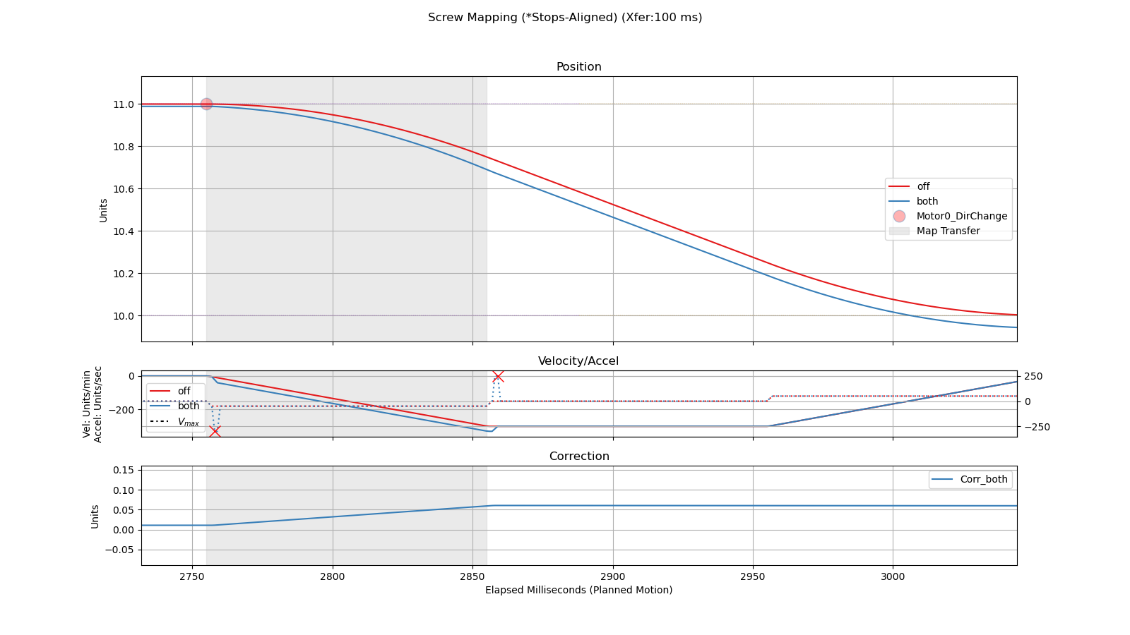
Consider what happens when the CNC changes direction and has to switch between two different maps. The G code for this example would look something like
G1 F300
X49
X50
X49
The graphs show motor position (red: no mapping; blue: mapping enabled) as well as velocity, acceleration, and the correction amount applied.
Transition Time: 100 ms (Value: 0.01)
Transition Time: 10 ms (Value: 0.1)
Note: the acceleration of the commanded move is quite high. This would probably cause a noticeable thump in the motion.
Transition Time: 200 ms (Value 0.005)
Note: the acceleration is lower, but it takes longer to transition to the negative map.
Screw Map File Format and Examples
(Using Actual Motor 0 / 1 / 3 Data)
Purpose
Screw-map files provide position-dependent error compensation in motor counts, enabling precise backlash and lead-screw error correction.
Each motor uses two maps — one for the positive and one for the negative direction of travel — which can be combined for full bidirectional characterization.
File Naming Convention
| Motor | Axis | Positive File Name | Negative File Name |
|---|---|---|---|
| 0 | X Axis | Motor_0_Map.dat |
Motor_0_MapNeg.dat |
| 1 | Y Axis (Master) | Motor_1_Map.dat |
Motor_1_MapNeg.dat |
| 3 | Y Axis (Slave) | Motor_3_Map.dat |
Motor_3_MapNeg.dat |
Files are placed in the same directory as the machine configuration.
File Format
Each .dat file is a comma-separated list of integers, representing the screw-map grid:
| Element Index | Description | Units |
|---|---|---|
| 1 | Starting position | counts |
| 2 | Ending position | counts |
| 3 | Number of points (N) | – |
| 4 → 3 + N | Error at each grid point | counts |
Example structure:
All values are in encoder counts, and the number of total integers must equal 3 + N.
Grid Spacing
Positions are evenly distributed:
Errors correspond one-for-one to these sample positions.
Interpolation
For intermediate positions, use linear interpolation:
Actual Map Summaries
| Axis | File | Start | End | Points | Min Err | Max Err | Range |
|---|---|---|---|---|---|---|---|
| X | Motor 0 Pos | 0 | 3 932 160 | 31 | 0 | 1114 | 1114 |
| X | Motor 0 Neg | 0 | 3 932 160 | 31 | 0 | 1121 | 1121 |
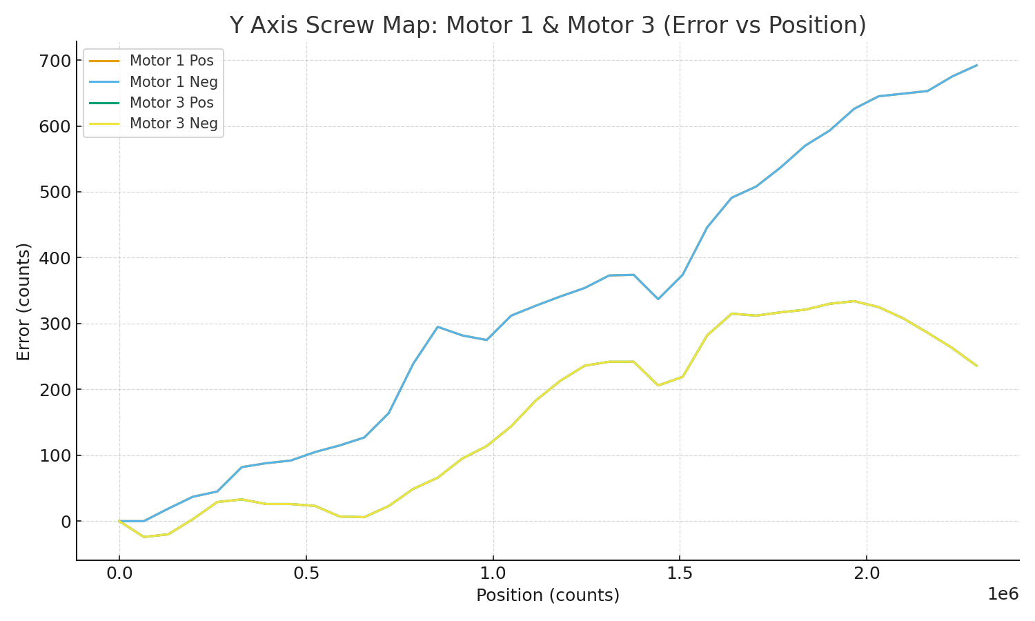
| Y | Motor 1 Pos | 0 | 2 293 760 | 36 | 0 | 692 | 692 |
| Y | Motor 1 Neg | 0 | 2 293 760 | 36 | 0 | 692 | 692 |
| Y | Motor 3 Pos | 0 | 2 293 760 | 36 | -24 | 334 | 358 |
| Y | Motor 3 Neg | 0 | 2 293 760 | 36 | -24 | 334 | 358 |
Visualization
X Axis – Motor 0
Combined positive and negative curves (negative side mirrored).
Y Axis – Motors 1 & 3
Both master and slave motors plotted together; each combines positive and negative directions.
Validation Rules
-
N ≥ 2 -
File must contain exactly
3 + Nintegers -
start < end(monotonic) -
All values in counts
-
Clamp out-of-range lookups to nearest endpoint


