Alexsys V2 Operator Manual
1. Overview
ALEXSYS is a programming system for CNC machining centers. That combines features of CAD / CAM systems with typical features of conversational programming.
It is not necessary to be experienced with CAD/CAM systems to use this software.
Some helpful video tutorials are available on our youtube channel:
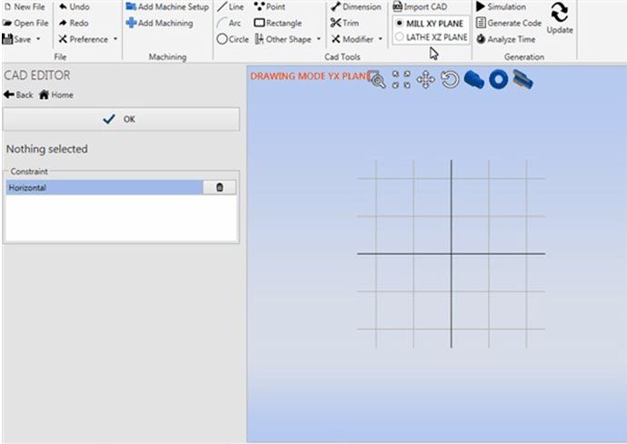
2. Cad Editor
ALEXSYS has a minimal cad editor.
You can create basic drawings or refine imported geometry.
The features available are:
- DXF / DWG Importing
- Drawing Tools
- Smart Dimension
- Move / Translate / Rotate / Scale
- Trim / Offset / Chamfer / Fillet
2.1 Drawing Tools
The available drawing tools are:
- Line
- Arc
- Circle
- Point
- Rectangle
- Regular Polygon
- Slot
- Arc Slot
- Text
- Coordinate List

2.2 Regular Polygon

2.3 Arc Slot

2.4 Snap System
To simplify the drawing there is a snap system, that allows tracing with other points already present in the drawing.
See the image on the below to better understand the concept

While drawing, holding down the [CTRL] key activate the angular snap, instead holding down the [SHIFT] key activate the grid snap.
2.5 Snap Tangent feature
Hover with mouse cursor on arc / circle entity.
When the nearest snap icon shows up, click on that arc/circle entity.
Now go with the mouse cursor on other arc/circle entity and click when the same snap type is visible.

This works both with segment and arc, see the images below:


3. Import DXF/DWG
With ALEXSYS you can import 2D geometries from DXF / DWG files. Click on [Import Cad] in ribbon menu.

Select in which plane you want import the geometries.
Select the entities to import, select nothing if you want import everything.

Click on [Import Selected] and done!

4. Smart Dimension
To draw, the first sketch the profile shape. Then use the command Smart Dimension and available constraints to define the profile accurately.
It is called smart dimension because with just one command you can define many things. It switches its purpose depending on which element you have selected.
4.1 One Segment
With just one segment selected, and depending on mouse position, you can define the:
- Horizontal line length
- Vertical line length
- Effective Line Length


4.2 Two segment
If there are 2 segments selected, and they are parallel each other, you can define the distance between them.
To set parallel constrain from 2 segment, select both (keep [CTRL] pressed and select them with mouse) and press [Parallel] from constraint list.

Then with [Dimension] activated, select both elements and define the distance between them.

If there are 2 segments selected, but they are not parallel, you can define the angle between them.

4.3 Arc Circle
If your selection consists in a circle or arc, you can define the radius.

4.4 Edit Existing Dimension
To edit, just double click on dimension and insert desired value. After that the geometry will update accordingly.
4.4 Reference Dim
If you want a reference dimension, not a constraint dimension, check the [Reference Dim] check box in the input dim value dialog.
5. Move:
- Translate
- Rotate
- Mirror
- Scale

6. Commands:
- Trim
- Offset
- Chamfer / Fillet
7. Fast Shape
When you have to work simple geometries, and you don't want to deal with cad tools, use Fast Shapes
7.1 Milling Operation:

- Coordinate List
- Circle
- Rectangle
- Regular Polygon
- Slot
- Arc Slot
7.2 Drilling Operation

- Circle
- Rectangle
- Coordinate XY
- Coordinate Radius Angle
- Line Pattern
- Arc Pattern
7.3 Lathe Operation:

- Coordinate List
- Step Profile
7.4 Adding Fast Shape
You can add a Fast Shape in 2 ways.
- Just select the desired shape during the machining selection:
- From geometry list menu, select [Fast Geometry]


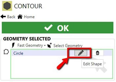
7.5 Edit Fast Shape
One of the pros of using this type of geometry definition is the ability to edit easily. The associated toolpath will be regenerated automatically.
To edit the shape click the pencil icon on related item in geometry list ![]() . Alternatively, you can double click in 3D Scene.
. Alternatively, you can double click in 3D Scene.
7.6 Remove Shape
If you want to remove it from geometry list, click the trash can icon ![]() . In this way you remove only the association from geometry and the machining. The shape is still present in the scene.
. In this way you remove only the association from geometry and the machining. The shape is still present in the scene.
To remove completely: right click while hovered and press [Delete], or press keyboard [Cancel] while selected.
7.7 Coordinate List
Simply insert coordinate list. Has integrated trigonometric function to find missing dimension. In the chamfer/fillet column you can insert the final chamfer/fillet. For chamfer insert positive values and for fillet negative values.
If you have a chamfer at 30 degrees, just insert 2x30:

To insert arc movements:
- Just click on the [Add Arc Movement]
 or
or - [Mouse Right Click] and click on [Switch Line To Arc] menu item.

7.8 Step Profile
This pattern is particularly useful in turning profiles definition. It can define only profile composed by a sequence of cylindrical step.
Diameter: Diameter of cylinder
Depth: Depth of this step
Chamfer: Positive value chamfer at 45 degrees. For not 45 degrees angles insert string for example 2x30 or 3x60. With negative value, will create a fillet

8. Tool definition
To select different tool or simply change machining parameter you need to open tool selection dialog.
You can open this dialog in several ways:
- Method 1
In machining screen, click on operation type description.

- Method 2
Click on tool name, on top bar up the 3D Viewport.

- Method 3
Click on highlighted icon,

And then on tool name.

- Method 4
Click on [Show Details] and then on tool name in relative column.

Once the tool dialog selection is shown you can choose a different tool, or change tool machining parameter. Press ok to update machining parameter.

8.1 Coolant (Mist / Flood) Selection and Setup
Selection:
In the tool dialog selection window, there is a Coolant dropdown menu option to select mist, flood, or neither/off for each tool:
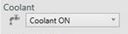
- Usage:
Dropdown Selection Related Terms Used Related M-Code Coolant ON Mist, Mist Coolant M7 High Pressure Coolant Coolant, Flood, Flood Coolant M8 Coolant OFF -- M9

Setup: To change the M-Code for each coolant option:
- When Generate Code is commanded, there is an Edit Tool Machine link in the window. Click on that and then on the Post Processor tab in the next window that opens, then search for coolant:
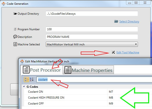
- Change the M-Codes as desired in the resulting field

9. Edit Mode ON / OFF
9.1 Edit ON
While you are in this mode you can create or edit the geometries. The lines are drawn in blue color, you can drag entities.
This mode is dedicated to drawing; you can't see any generated toolpath while you are in this mode.
To enter in this mode you can:
- Double click on the geometry (or fast shape) you want to edit
- Set Toggle Switch to ON
- Click [Edit Shape] button in geometry list

9.2 Edit OFF
This mode is supposed to prevent unwanted edits to the geometries. The entities are drawn in black color.
In this mode you can't drag entities. You can see the generated toolpath.

10. Geometry Selection
In almost every operation you need to associate some compatible geometry to the operation you want to perform.
To do this association, add the geometries to the geometry list.
10.1 Geometry List
The associated geometries are listed:

To add existing geometry, click on [Selected Geometry] button or click directly in the white space of list control.
When you are in selection mode, the list background will become light blue. Now you can select entities in the 3D control.
Selection Mode Active:

You can pick entities one by one or by selection box.

Consecutive lines and arcs are grouped together.
When the selection is valid, the list border is green.
When there is nothing selected, the border list will become red.

To edit the geometry click ![]() button.
button.
To remove the association click ![]() button.
button.
Note: Only the association from machining and geometry are removed. The geometry is still existent.
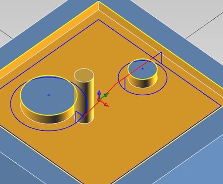
10.2 Overlapping Geometries
If Alexsys detect two or more overlapping geometries, it merges their outer profile. In the example below are selected a circle and a rectangle.
Alexsys will create a unique result profile:

10.3 Pocket Isle
If the geometry is completely contained in another shape, a pocket isle will be created. This is only possible with pocket operation.

11. Setup Definition
All the machining operations are grouped in machine setup.
Depending on the machine you intend to use (vertical mill / lathe) you need to add different setup type.
Lathe Setup

Mill Setup

In the HOME treeview you can see all the operations are grouped by setup.

In setup screen you can define properties like setup name, origin (G54, G55,..), G-Code program number, select machine definition.
In lathe setup, you can set the spindle revolution limit.
If you add a second setup, you have to choose if you want continue from previous setup, or create a new setup.
If you choose NEW SETUP, a different file will be created for G-CODE.
Otherwise if you select CONTINUE FROM PREVIOUS SETUP, the code will be added in the same file.
It is also possible to change position of the stock, trough action Stock Position.
If you are doing a lathe part, probably you need only to flip the 3D model of stock. In this case check the Flip Stock property.
You can write the message to show between the different setups:

12. Stock Definition
It is possible to define the raw stock only in the first machine setup. Click on Stock item, in tree view.

The material will be used to select the correct tool cutting data parameter.
Instead the geometry will be used in milling operation to create the toolpath optimization, basically to cut off the movement outside the stock geometry.
You can choose from:
- Rectangular shape
- Circular shape
- Hexagon shape
- Custom shape (only with milling setup)

You define the geometry of custom shape, selecting the entities like you do when you have to associate geometry to machining operation.

Note: To have better performance I suggest keeping the stock geometry simple as possible.
13. Milling Start Point Definition
Alexsys by default tries to set as initial point of toolpath the topmost position.

It is possible to change the initial point, checking the field [Select Start Point].
After checking this property it will become visible the fields where you have to insert the starting point.
You can easily pick the point with mouse. Move the mouse to 3D view; you should see an orange dashed line.
The Snap toggle button has to be activated to get the mouse snap active.

Note: The initial point will not be the picked point itself. But the closest point of toolpath to the picked point.
14. Hide/Show Geometry
To maintain the 3D scene clear as possible, once the geometry is used by an operation, the geometries become hidden.
This means it is visible only when you have selected the related operation. To force the visibility of all the geometries, you can click on [Preference] >> [Show hidden geometry]

In this way all the geometries are visible and you can pick some geometry for another operation, for example.
The geometries that are not linked with any operation (orphaned geometry), remains visible.
Hide end points
By default, when you draw arcs, circles or lines, the endpoints and center points are visible. These points are necessary, since ALEXSYS have a parametric drawing system.
But when you need to import a bit more complex geometries, the scene can become a little messy. Like in this image.

To solve this issue you have to check the [Preference] >> [Hide end points] property
15. Toolpath Simulation
Back plotting
With Alexsys it is possible to simulate the movement of the tool in space to let you know understand quickly the generated path.
There is no collision detection, it just back plots the tool moves in 3D scene.
You can drag the cursor to the [Timeline] to go fast in the toolpath point you want. You can make it transparent model of the tool or hide it. It shows the current position and the current values of progress and speed.
By default it just processes a single operation per time, but you can check Continue with next operation to continue the simulation.
To view the simulation, press the simulation command when a toolpath is present:

Then in the left column of interface will appear the simulation screen. Here you can control the back plotting and read the current parameter and tool position.

16. Machining Types
With ALEXSYS you can generate milling cycle for vertical mill and for c-axis in lathe with live tools. The available machining types are:
- Face Milling
- External Contouring
- Pocketing
- Drilling / Tapping / Boring / Thread Milling /...
- Chamfering Operation
- Engraving
- 2D Profile Cutting
- Cutter Diameter Compensation
- Multi WCS (repeat same toolpath on several origins, G54, G55,...)
17. Face Milling
For this machining, you can decide to execute:
- Roughing
- Finishing
- Chamfering
Just select them from child operation group:

The effective dimension of the stock are picked from stock definition screen.
18. External Contouring
Set a positive value [STOCK TO REMOVE].

19. Pocketing
- Pre-drill on plunge point
- Plunge Mode
- Material to remove
- Circle Strategy
19.1 Pre-drill on plunge point
Plunging with end mill is a stressful operation. For this reason the possibility to add a center drill and drill operation in the points where the tool mill will plunge have been added.
These points are calculated automatically. You just need to select drills operations:

Now in the home screen will be present 3 operations, related to the same pocket machining. You can change the order of this machining through 3 commands:
- Move Down Operation
- Move Up Operation
- Automatically Sort Operation List

This is the preview of roughing operation; you can see the points where the mill will plunge
In that coordinate the pre-drill will be executed.

19.2 Plunge Modes
In the pocket machining you can edit the mode the tool plunges into the material. The feed used in these moves are the Plunge Feed set in tool parameter screen.
Plunge modes available:
- Straight
- Helix / Helicoidal
- Step
- Ramping

19.2.1 Plunge Straight
This is the easiest and fastest way to plunge, but it is the most stressful both for machine and tool. I suggest doing a pre-drill if you intend to use this plunge mode. The milling tool needs the capability to plunge directly
19.2.2 Plunge Helicoidal
This is less stressful mode but slower. The machine needs to move the XYZ axis at same time.
Helix Diameter: if you set 0, the helix diameter will be 20% more the tool diameter.
Helix Angle: Is the angle of generated helix, every end mill has different helix angle value.
If the helix plunge is not possible in some points, because the helix overlaps the geometry profile for example, straight plunge will be used.
19.2.3 Plunge Step
This is similar to drill peck macro for drill tool. It is suggested to use this when the pocket is less than 1.5 x tool diameter, and to make a pre-drill. This is a compromise from the straight and helix modes.
19.2.4 Ramping
Has the same benefit of helicoidal entry, it just follows the innermost profile. You can edit the ramp angle.
19.3 Material To Remove
Sometimes you have a semi-machined stock, and so you need to remove only some material from the original profile. To manage this case you can set the [Stock to remove]. If it's greater than 0, the machining don't start from center of the pocket but from a distance equal to the inserted value.

19.4 Circle Strategy
When in the geometry to machine, a circle shape is found, you can choose between these strategies with the [Circle Roughing Mode] option:
- Spiral
- Traditional
- Helix / Helicoidal
19.4.1 Spiral Strategy

19.4.2 Traditional Strategy

19.4.3 Helix Strategy

20. Drilling / Tapping / Boring / Thread
Overview
All the drilling operations are grouped under unique machining. In doing so, you can select the geometries one time, and can insert multiple operations.
Example
Let say, for example, you want to do a thread mill. You may need to use a
- Center drill
- Drill
- Enlarge the hole with end-mill
- Thread Mill
- Chamfer Mill
With this machining you need just to select the tool you need and insert the requested parameter.
If you edit the geometry, all the toolpaths are also updated.
Tools Supported
- Center Drill Drill
- Tap Bore
- Counter-bore
- End Mill (for enlarge holes)
- Spiral
- Helix
- Traditional
- Thread Mill
- Chamfer
- Chamfer Mill
Where applicable, in the output code will be present standard canned cycle.
Thread Table
Both in the TAPPING and THREAD MILL operation is present the precompiled thread table.
In this way you don't have to bother searching for thread parameters.

Once you select the thread, also the predrill diameter is updated accordingly
21. Engraving
With ENGRAVING machining is possible to engrave text (both single line and True Type), with any font installed in the pc.
The text can be linear or circular.
And of course all the selected geometry can be engraved.

22. Chamfering operation
It is possible to insert a chamfering operation, just enabling Chamfering operation.
Set the desired chamfer value, Alexsys will take care of calculating the effective tool depth Z based on the selected tool geometry (nose radius, diameter).

Chamfer operation is available on almost every milling machining.
Note: Sometimes the chamfer will not be correctly modelled in stock preview, but the toolpath generated should be.
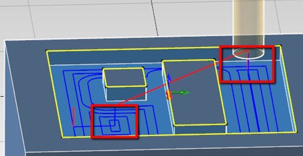
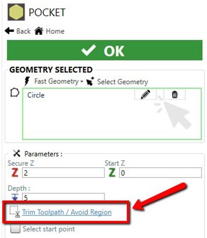
23. Trim toolpath
To prevent unnecessary air movement, with Alexsys is possible trim toolpaths in several way. First go to Trim Toolpath / Avoid Region screen. Click in highlighted link.
Trim outside stock
Now you can choose to trim the toolpath outside the stock profile. Simply check Trim Toolpath outside stock option.

After that you can see the toolpath is already trimmed.

Trim by selected geometry
This option is similar to the Trim Outside stock, but the trim geometry is defined by user selection.

Avoid selected geometry
It is also possible to avoid some defined geometry.

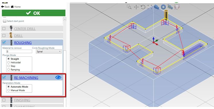
24. Remachining operation
(Or rest machining)
When you have to clear a large area, you are probably going to use an end-mill with larger diameter to speed up the machining time. The downside is a lot of material remains in corners, so you need to remove it.
The remachining operation solves this issue by going to remove the uncut material from previous operation.
Rest machining with smaller end mill:
Previous operation with larger end mill:

25. Conventional / Climb Direction
To change the mill direction:
First go to the TOOL PARAMETER screen.
To go to TOOL PARAMETER screen, if you are in the HOME, search this icon ![]() and click on that
and click on that

Or if you are in a MACHINING screen click on related operation link

When you are in TOOL PARAMETER screen, change to desired mill direction.

26. Mill Cutter Compensation
Control compensation is only applied for finishing passes.
In ALEXSYS there are 3 compensation modes available:
- Computer Mode
- CNC Mode
- Tool Wear Mode

26.1 Computer Mode
This is the most compatible mode, since all the final path is calculated automatically. The output code doesn’t contains any command related to compensation (usually G41 - G42)
But it's not possible to adjust the toolpath by the tool corrector table. If don't have to worry about setting tool diameter in Tool Diameter register.
So it's not indicated if you have to keep tight tolerances in your work-piece.
Computer Compensation Mode:

26.2 CNC Mode
This is the least compatible mode. The output path reflects exactly the geometry profile. All the offset are calculated by the cnc machine.
An approach move is necessary to enable tool compensation.
In the output code is present code for enabling / disabling cutter compensation (usually G41/G42/G40).
The linear approach movement is 20% more than the tool diameter. At now is only possible do this movement at secure z and then after the radius comp. is on, move to work z with plunge feed.
Here it is necessary to set the tool diameter in cnc tool register, and adjust it if is necessary to compensate the tool deviation.
The toolpath preview always shows the uncompensated path. This issue can be misleading in CNC Compensation Mode.
CNC Compensation Mode:

26.3 Tool Wear Mode
This tends to be the most versatile mode.
The offset diameter is calculated by the computer, but you can adjust the toolpath anyway by editing the tool wear registry in cnc machine.
This permits to have less incompatibility issues with cnc.
In the output code there is code for enabling / disabling cutter compensation (usually G41/G42/G40).
One downside is you have to use end-mill with the same diameter used in Alexsys. But it's not a big deal since you can synchronize quickly the generated code and upload to machine.
Tool Wear Compensation Mode:
26.4 Output Code
To help the machinist have clear understanding of what compensation is enabled and what values are being used, the output code has this information visible, both in tool summary and when the tool is actually called:
Tool Summary:
(#7 - END MILL D 8MM COMP COMPUTER - RADIUS COR VALUE 0)Tool Called:
 N5
(POCKET - FINISHING)
(COMP COMPUTER - RADIUS CORRECTOR VALUE 0)
(END MILL D 8MM)
26.5 CNC Compensation Example:
Tool Summary:
(#7 - END MILL D 8MM COMP NCCONTROL - RADIUS COR VALUE 4)Tool Called:
 N5
(POCKET - FINISHING)
(COMP NCCONTROL - RADIUS CORRECTOR VALUE 4)
(END MILL D 8MM)
26.6 Tool Wear Example:
Tool Summary:
(#7 - END MILL D 8MM COMP TOOLWEAR - RADIUS COR VALUE 0)Tool Called:
 N5
(POCKET - FINISHING)
(COMP TOOLWEAR - RADIUS CORRECTOR VALUE 0)
(END MILL D 8MM)
You can see what compensation mode is going to be activated, and what value have the machinist have to insert in the registry.
From these comments, you have to set the tool diameter only with CNC Compensation, with the other two modes you have to set the tool diameter to 0.
27. Cutting 2D Profiles
This is the machining you need to use when you want cut 2D Profile from material sheet. Just select the geometries of the profile you want to cut.
Select the relative position of the tool:
- Internal
- Central
- External


Holding tabs
Holding tabs are needed in order to keep your cut part stable after the machining. In this way the machine or tool are not damaged.
You need to manually remove the cut part from sheet. Check the property ADD HOLDING TABS.
To create these holding tabs, the tool needs to raise at some points.

You have to define the thickness and length of these holding tabs.
To define the position you can proceed manually or use the automatic method.
Automatic
With automatic method, you need to set the holding tabs you want to add. The positions are calculated automatically.
Manually
If you want to set the holding tabs in precise point, you need to proceed in manually way.
Select the manual mode, click on Snap ON button, and pick the point with mouse in 3D scene.


Graphically holding tabs are represented only by a purple element, has no effect on 3D stock model
28. Multi WCS
In milling operations, you may have the necessity to repeat the same toolpath in various WCS (G54, G55, G56,... ), so you can create the same part multiple times, in just one setup.
To do this, select Multi Origins from setup screen.

How it works
I've made the example part, you can see in the image below. Now I select WCS 1, WCS 2, WCS 3, from setup screen.
All the operation will be repeated in all this different origins.
Between this operations, will be called tool change only when it's necessary.

!! Important Warning !!
It is crucial to have the {ORIGIN} tag in this template:
Operation Head Code (without TOOLCHANGE)
This template is called between 2 operations, with the same tool, and it should be like this:
 {EMPTY_LINE}
 ({OP_DESC})
 {ORIGIN}
 {SPEED_MODE}S{SPEED_VALUE}{SPINDLE_ORIENTATION}
You can edit it from Post Processor Dialog:

For an explanation on what is a WCS, here an explanation video.
29. Mouse
Default Mouse Gesture:
Rotate
Use: Middle Button
Pan
Use: Middle Button + CTRL
Zoom
Use: Middle Button + SHIFT or MOUSE WHELL
Customization
You can personalize the mouse gesture and command through preference dialog
If the fields are empty, default value will be used.

30. User Interface
Disable Stock Modelling
To gain performance you can disable the stock modelling.
Disable Different Color
If you want the stock to be just one single color, instead of have a different color for every machining.
Select the tool mode
This change the representation mode of the tool in the scene. You can select between:
- Transparent
- Visible
- Hide
Stock Base Color
This is the initial color of the stock
Disable thread highlighting
By default, all the tread surface, are represented with a reserved color. You can disable this.
Thread Reserved Color
This is the default color of thread surface
You can edit these properties through preference dialog

Grouping MAX Gap
When you import geometries from cad file, it is possible for two adjacent entities to have exactly the same endpoint, but they have a little gap.
This can cause some problem in profile selection or toolpath generation.
To overcome this problem is possible to set the property [Entity Grouping - MAX GAP]

31. Dimension
It is possible to customize:
- Text Height
- Head Type
- Arrow
- Tick
- Dot
- Head Height

32. Threads Table
It is possible to add new thread or edit existing, through thread table dialog. To open this dialog:

All the threads are grouped by category: metric - NPT - UNC - etc.
To insert new threads, write down in the yellow line, at the end of the list. Once you [Save And Exit], the new thread will be available in threads selection list.

Edit Pitches
To edit pitch value, simply click on [Pitch Details] it is possible to edit:
- External Thread Height
- External Passes Count
- Internal Thread Height
- Internal Pases Count
Edit Category
Also the thread category table is possible to edit:
- Description
- Unique ID
- Select between TPI and Pitch values
- If is tapered
- Taper Angle
This information will be used in code generation.

33. Default Values
This feature allows you to store your custom default values.
Let's say, for example, when you need a face turning operation, often you need to change the [Material to remove] to 4mm, the [Finish Allowance] to .1mm and activate the finishing operation.

You can insert these values, press the Star icon, and at the next time you are going to add a face turning operation, that value will be set as default.
This also applies for setup and stock definition.
Reset default values
It is possible to restore default settings, by pressing the little arrow and the [Reset Default Values]

34. Cutting Operation tutorial
1 - Add mill setup
From ribbon menu select [Milling] -> [Vertical Mill]

[INIT NEW SETUP] side screen define your project preferences like program name, tool machine, setup secure z and other properties.
Press [OK]
[STOCK DEFINITION] in this screen you can change stock dimension, change the thickness to 40 to 3

2 - Import geometries from cad file
From main menu select [Import CAD] command. Now select and open DXF file.
The import plane is already [Plane XY], no need to change.
To import all the geometries, don't make any selection. To import only certain geometries, select them.
Press [Import Selection]
3 - Translate geometries
If needed, hide the end points to get a cleaner scene. From menu [Preference] -> [Hide End Points].
In this example, the shape needs to be centered to X0 Y0 coordinate:

Select all the entities and then press the snap button relative to translate start point. Be sure you have selected [DELETE original selected geometry] option.
With the help of snap system, pick the center shape and then move it to X0 Y0

4 - Add Cutting operation
From menu, [Milling] -> [Cutting Profiles] -> [Select existent geometry]
Check you have [Chain Selection] active.

Start picking all shape profiles.
To add two holding tabs, check the [Add Holding Tabs] option.
Select [Manual Mode], active the snap and then select the holding tab position.

Length and height of holding tabs are customizable.
5 - Select the tool
If you want select another tool or change some cutting parameter, open the tool dialog window.
6 - Drilling operation.
The geometries used in other operation become hidden; this is useful to obtain a clean scene.
With mouse drag a selection triangle around all remaining circle geometries
By default, only drilling operation is active, change the desired hole diameter and depth.
The tool selection is updated accordingly to hole diameter.
7 - Sorting Operation
As you can see from tree view in home screen, the drilling operation is after the cutting operation.
To change the order, select the operation you need to move and press the up or down arrow. It is possible to use the [Auto Sort] command.

8 - Generate Code
Press [Generate Code] to obtain the code.
35. Appendix
Warranty Information
MachMotion warranty policy is subject to change. Updated information is available at our website:
https://machmotion.com/warranty
The MachMotion Team
http://www.machmotion.com
14518 County Road 7240, Newburg, MO 65550
(573) 368-7399 • Fax (573) 341-2672
36. Videos
Alexsys™ by MachMotion - Conversational Assistant - Import CAD Demo