MachMotion Probing Wizard
![]()
Overview
The wizard is embedded in the MachMotion Mill 1150M – Probing and MachMotion Mill 2150M screens, but it can be accessed through any screen by selecting it from the available wizards. The full wizard is shown below. On the left side is a set of probing options as shown in the below figures.
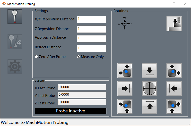
Figure 1 Edge Finder

Figure 2 Angle Finder

Figure 3 Settings
General Settings
The following options can be set on the 'Settings' page of the wizard and will be applied across both edge finding operations and angle finding operations.
First Touch: This is the first field in the 'Feedrates' section of the settings. This value is the feed rate that the probe will use for the first touch of each probe operation. It is required to be positive.
Second Touch: This is the second field in the 'Feedrates' section of the settings. This value is the feed rate that the probe will use for the second touch of each probe operation, if the double-touch feature is enabled. It is required to be positive. This is typically a slower feed rate for a more accurate reading.
Reposition: This is the third field in the 'Feedrates' section of the settings. This is the distance that the probe will retract from the part after each touch.
Wireless Delay (ms): If the configured probe is wireless, an optional number of milliseconds here can be added as a delay during probe arming, in order to allow the probe to complete the arm sequence before checking for errors.
Double-touch: Check this box to use two probe touches during all probe moves. If this box is unchecked, all probes will use only one touch and will do their touch at the 'First Touch' feed rate.
Probe Diameter: This is the diameter of the probe stylus being used. This must be an accurate number in order to get an accurate fixture offset.
Probe Code Options: The user can specify which probe signal to watch for while running a probe operation. In Mach, G31 corresponds to the “Probe” input signal, G31.1 is the “Probe 1” input signal, G31.2 is the “Probe 2” input signal, and G31.3 is the “Probe 3” input signal. The probe must be wired and mapped correctly to the selected signal for these operations to work.
Edge Finding Settings
Edges have two options for when the probe makes contact. The work offset can be zeroed at the edge or the position where the edge is found can be reported without zeroing. This selection is made in the 'Settings' group on the edge finding page. The following settings apply to edge finding of either type.
X/Y Reposition Distance: This is the distance used for the X and Y axes to travel in free space during corner findings. It should be a large enough distance for both axes to clear the edge of the corner. These moves will be made as protected moves.
Z Reposition Distance: This is the distance the Z will move in free space during corner findings. It should be greater than your retract distance, in order for the Z axis to reach the side of the material. This move will be made as a protected move.
Approach Distance: All axes will use this value when doing a probe move for both edges and corners. It is the maximum distance the probe will move while searching for material. If the probe is not activated before this distance is consumed, then an error will occur and the operation will be stopped.
Retract Distance: This distance is used after a probe touch to remove the probe from the side of the material. It should be a sufficient distance to deactivate the probe. This distance is also used during the probe double-touch if that feature is activated.
Angle Finding Settings
Angles have two methods of being measured. For small pieces with no movement interference, there are four canned functionalities. These options will probe the side of the part, then move a specified distance along the part, and probe the side again. If the part is large or the user wants more control over measuring the angle, they can enter Jog Mode. Once they activate this mode, they can probe a side of the material, then jog the machine to a new position and probe the side again. This is useful to expedite travel from one end of a part to another.
Angle Measure Options: There are five options for the user to choose from here. This selection will determine how the machine operates during an angle probing operation.
X--: The probe will move in the negative X direction. This means it will be touching the east side of the part.
X++: The probe will move in the positive X direction. This means that it will be touching the west side of the part.
Y--: The probe will move in the negative Y direction. This means it will be touching the north side of the part.
Y++: The probe will move in the positive Y direction. This means it will be touching the south side of the part.
Jog Mode: The probe will move in the direction that the user chooses later.
Reposition Distance: This is the distance that the probe will move between the two probing operations of an angle probe. It can be positive or negative. It is only used when not in Jog Mode. This move will be done in as a protected move at the 'First Touch' feed rate.
Approach Distance: This is the distance that the probe will attempt to move in order to probe the material. If the material is not reached before this distance is consumed, then an error will occur and the operation will stop. This value should be a positive value.
Retract Distance: This distance is used after a probe touch to remove the probe from the side of the material. It should be a sufficient distance to deactivate the probe. This distance is also used during the probe double-touch if that feature is activated.
Status
There are two sections to the Status column that appears on all pages other than 'Settings'. The first section shows the last probed position for the X, Y, and Z axes. The positions will be shown in work coordinates, unless the "Machine Coordinates" signal is active, in which case they will be shown in machine coordinates.
The second section is an LED that indicates if the currently selected probe is active or not. If in the settings, the user has G31 selected, then the LED will correspond to the input signal “Probe”. If they have selected G31.1, then the LED will indicated that status of the input signal “Probe 1”. The LED will mark the state of the input signal “Probe 2” if the user has selected G31.2 in the settings, and the LED will correlate with the “Probe 3” input signal if the user selected G31.3.
Functions
There are fourteen functions that the probing wizard can do. There are four operations that find a single edge of the part, four operations for finding a corner of the part, one operation to find the center of a circle, one operation to find material top (Z axis), and four operations to find the angle of a part.
When commanding any probe motions, be sure that your ‘Probe Code Options’ field is set to the correct probe.
Edge Finder

Corner Finder

 The first button, which will zero on the top left corner, will start by moving downwards and locating the top of the part. It will do a full two-touch routine (if enabled) and then zero the Z axis. Next, it will move in the positive Y axis the distance specified in your ‘X/Y Reposition Distance’ field. It is important that the distance is correct in order to properly be clear of the part. After this move, Z will descend by the 'Z Reposition' distance. Once the Z has been lowered, the probe will move in the negative Y direction and probe the top edge of the part. This is the same routine as the corresponding edge finder. After probing Y, the Y axis will be zeroed and the Z will raise up. The Y axis will return back to its starting position over the part. Then X axis will move in the negative X direction the reposition distance so that it will be clear of the part. The Z will again descend the same Z reposition distance. At this point, the X axis will perform a full probe routine in the positive X direction. After probing the X edge and setting the zero, the Z axis will raise up, the both X and Y will move to zero. At the end of the routine, X and Y will be at zero and the Z axis will be at the retract distance away from its zero point.
 The second button, which will zero on the top right corner, will start by moving downwards and locating the top of the part. It will do a full two-touch routine (if enabled) and then zero the Z axis. Next, it will move in the positive Y axis the distance specified in your ‘X/Y Reposition Distance’ field. It is important that the distance is correct in order to properly be clear of the part. After this move, Z will descend the 'Z Reposition' distance. Once the Z has been lowered, the probe will move in the negative Y direction and probe the top edge of the part. This is the same routine as the corresponding edge finder. After probing Y, the Y axis will be zeroed and the Z will raise up. The Y axis will return back to its starting position, over the part. Then X axis will move in the positive X direction the reposition distance so that it will be clear of the part. The Z will again descend the same Z reposition distance. At this point, the X axis will perform a full probe routine in the negative X direction. After probing the X edge and setting the zero, the Z axis will raise up, the both X and Y will move to zero. At the end of the routine, X and Y will be at zero and the Z axis will be at the retract distance away from its zero point.
 The third button, which will zero on the bottom left corner, will start by moving downwards and locating the top of the part. It will do a full two-touch routine (if enabled) and then zero the Z axis. Next, it will move in the negative Y axis the distance specified in your ‘X/Y RepositionDistance’ field. It is important that the distance is correct in order to properly be clear of the part. After this move, Z will descend the 'Z Reposition' distance. Once the Z has been lowered, the probe will move in the positive Y direction and probe the bottom edge of the part. This is the same routine as the corresponding edge finder. After probing Y, the Y axis will be zeroed and the Z will raise up. The Y axis will return back to its starting position, over the part. Then X axis will move in the negative X direction the reposition distance so that it will be clear of the part. The Z will again descend the same Z reposition distance. At this point, the X axis will perform a full probe routine in the positive X direction. After probing the X edge and setting the zero, the Z axis will raise up, the both X and Y will move to zero. At the end of the routine, X and Y will be at zero and the Z axis will be at the retract distance away from its zero point.
 The fourth button, which will zero on the bottom right corner, will start by moving downwards and locating the top of the part. It will do a full two-touch routine (if enabled) and then zero the Z axis. Next, it will move in the negative Y axis the distance specified in your ‘X/Y RepositionDistance’ field. It is important that the distance is correct in order to properly be clear of the part. After this move, Z will descend the 'Z Reposition' distance. Once the Z has been lowered, the probe will move in the positive Y direction and probe the bottom edge of the part. This is the same routine as the corresponding edge finder. After probing Y, the Y axis will be zeroed and the Z will raise up. The Y axis will return back to its starting position, over the part. Then X axis will move in the positive X direction the reposition distance so that it will be clear of the part. The Z will again descend the same Z reposition distance. At this point, the X axis will perform a full probe routine in the negative X direction. After probing the X edge and setting the zero, the Z axis will raise up, the both X and Y will move to zero. At the end of the routine, X and Y will be at zero and the Z axis will be at the retract distance away from its zero point.
Circle Center
 This function will find the center of a circle and zero there. It will only work with holes, not posts. The probe must start already lowered into the hole. The probe will first move in the negative X direction and probe the side of the circle, and then return to its starting position. All probe operations will do two full touches of the part, if the double-touch feature is enabled. After the first edge, the probe will then probe in the positive X direction, then return to the starting position. You should be sure the approach distance will reach both sides of the circle. After the second X axis probe, the operation will be repeated in the Y axis. The probe will first move in the positive Y direction and probe an edge of the circle and return to start. Then the probe will move in the negative Y direction and find the edge there. At this point, the machine will calculate the center of the circle, and move to position. Upon arrival, it will zero both the X and Y axes.
Zero Z Axis
 This function will probe the part in the negative Z direction. The Z axis will move the approach distance while trying to find the part top. If the double-touch feature is enabled, then the Z axis will probe twice. After finding the top of the part, the probe will zero its position and retract the specified retract distance.
Measure Angle

There are five methods to measure the angle that a part sits at. You can probe using one of the four canned probing functions or you can manually probe the angle using Jog Mode. Each function requires two probe routines to complete. The probe will touch the side once, move a certain distance, and then touch the side again. The canned functions use the ‘Reposition Distance’ parameter as the distance to move along the part. This parameter specifies both direction and distance between the two probe operations. If it is positive, then the probe will move in a positive direction up the side of the part before doing the next probing operation. If it is negative, then the probe will move in a negative direction down the side of the part before doing the next probing operation.
 The first function will move the probe in the positive X direction, thereby probing the left edge of the part. The probe will do one full probe operation against the side of the part. Then it will retract. After retracting, it will move the Y axis the distance specified in the ‘Reposition Distance’ field. For instance, if ‘Reposition Distance’ is set to 1, then the Y axis will move positive 1 unit (inches or millimeters). If ‘Reposition Distance’ is set to -1, then the Y axis will move 1 unit in the negative direction. After this move, there will be a second probe operation in the positive X direction. When it is complete, the probe will retract from the part and set the appropriate angle.
 The second function will move the probe in the negative X direction, thereby probing the right edge of the part. The probe will do one full probe operation against the side of the part. Then it will retract. After retracting, it will move the Y axis the distance specified in the ‘Reposition Distance’ field. For instance, if ‘Reposition Distance’ is set to 1, then the Y axis will move positive 1 unit (inches or millimeters). If ‘Reposition Distance’ is set to -1, then the Y axis will move 1 unit in the negative direction. After this move, there will be a second probe operation in the negative X direction. When it is complete, the probe will retract from the part and set the appropriate angle.
 The third function will move the probe in the positive Y direction, thereby probing the bottom edge of the part. The probe will do one full probe operation against the side of the part. Then it will retract. After retracting, it will move the X axis the distance specified in the ‘Reposition Distance’ field. For instance, if ‘Reposition Distance’ is set to 1, then the X axis will move positive 1 unit (inches or millimeters). If ‘Reposition Distance’ is set to -1, then the X axis will move 1 unit in the negative direction. After this move, there will be a second probe operation in the positive Y direction. When it is complete, the probe will retract from the part and set the appropriate angle.
 The fourth function will move the probe in the negative Y direction, thereby probing the top edge of the part. The probe will do one full probe operation against the side of the part. Then it will retract. After retracting, it will move the X axis the distance specified in the ‘Reposition Distance’ field. For instance, if ‘Reposition Distance’ is set to 1, then the X axis will move positive 1 unit (inches or millimeters). If ‘Reposition Distance’ is set to -1, then the X axis will move 1 unit in the negative direction. After this move, there will be a second probe operation in the negative Y direction. When it is complete, the probe will retract from the part and set the appropriate angle.

Using Jog Mode allows the user to fully select where to probe the part for both positions. To activate it, select ‘Jog Mode’ from the Measure Angle Options, the press the angle button. It will be green while Jog Mode is active. To cancel Jog Mode, which will discard any points it has probed, press the button again to return it to its normal state. While Jog Mode is active, the user can jog to any position around the part and probe it using one of the four standard edge finding probe operations. The selected function will perform the same routine that it would under normal conditions, completing a full probe routine. After the routine is completed, the user is free to jog the machine wherever they desire in order to probe again. The only restriction is that both probe operations must be of the same type (i.e. probing positive X and then negative Y is not allowed). After two probe positions have been collected, the angle will be set appropriately and Jog Mode will turn itself off.
The MachMotion Team
14518 County Road 7240, Newburg, MO 65550
(573) 368-7399 • Fax (573) 341-2672