Alexsys V4 Turn Operator Manual
Overview
ALEXSYS is a programming system for CNC turning centers that combines features of CAD / CAM systems with typical features of conversational programming.
It is not necessary to be experienced with CAD/CAM systems to use this software.

The lathe module support all the most common turning operations.
- Face Turning
- External / Internal Turning
- External / Internal / Face Grooving
- Central Drilling
- External / Internal Threading , also tapered threads
- Cut-Off
Face Turning

Diameter Mode - Auto : Start and end diameter value are defined by stock dimension
Diameter Mode - Manual Values : Start and end diameter value are defined manually
Start Z : Reference Z , usually it's always 0
Corner Mode : Choose between chamfer or fillet
Init Chamfer : It the chamfer/fillet value.
Child operations:
1) Roughing Operation
Material to remove : Is the material width to remove , measure from Start Z to Z+ direction
Finishing allowance : Is the material width left to finishing operation by the roughing operation
2) Finishing Operation
No options for this operation.
Generic Turning
External Cycle : The tool moves from the outside the inner part of the component.

Internal cycle : The tool moves from the inner part of the component to outside.
Before proceed with internal cycle is necessary create a central hole in the component.
In important also use a tool with dimension compatible with this hole diameter.
You can find this information in tool catalog.

To add this operation, from [MENU] -> Lathe -> External or Internal Turning , depending on your needs.

Here the screen related to external / internal turning machining.

Geometry Selection
Generic turning accept as geometry both open profiles and closed profiles.
It's suggested to link just a single profile in geometry list.
Open Profile:

Closed Profile:

Turning Parameters
Turning direction - Traditional : Tool direction it's from Z+ to Z-
Turning direction - Reverse : Tool direction it's from Z- to Z+ , you need to select a compatible tool when you change this property.
Profile Start/End Extension : A tangent extension will be added to start/end of selected geometries
Apply Fillet on sharp corner : Where applicable, a fillet will be created in sharp corner.
Toolpath Limit : With this you can define the limits of working area.
Without Limit :

With Limit :

Operation 1 of 2 : Roughing
Finish Allowance X / Z : It's the material thickness left by the roughing tool for the finishing operation.
Roughing Macro : Where applicable , it will print G71 macro code in output code instead of simple movements
Finish with same tool : Finishing allowance material will be removed by the roughing tool
Operation 2 of 2 : Finishing
Reverse direction on vertical wall : When enable , the turning direction will be inverted in 90° profile element. In some context , this may reduce tool vibration.
Vertical wall threshold : Will be considered only elements with length bigger than this value.
Multiple finishing passes : It create multiple finishing passes. The distance between passes is determined by finishing allowance thickness.
example : If you have a 0.3mm of finish allowance and 3 finish passes. Toolpath will generate 3 passes with a 0.1mm distance between them.
Lathe Central Drilling
To add a drilling machining , from Menu -> Lathe -> Central Drilling
This is the machining property screen.

Here you can enable these sub-operations :
- Center Drill
- Drill
- Chamfer
- Tap
- Reamer
You can change the sub operation order manually from treeview. See related link at the bottom of this article.
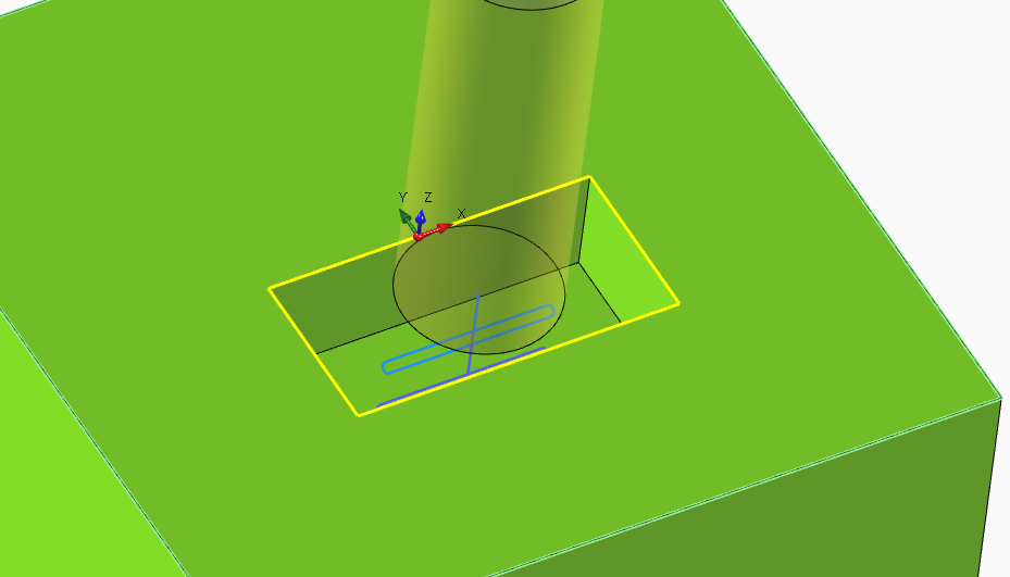
When a drilling operation is selected, is possible see also "ghost tool model" at the minimum reached z.
This is useful to check the tool path correctness at glance.
Safe Z : It's the Z Level of approach . The tool arrives at this level in rapid.
Start Z : This is the effective start working level. Usually it's 0
[Drill Operation] Add Drill Tip Length : It calculate the drill tool tip length and add it to inserted depth.
The drill tip length is calculated by tool diameter and tool angle. You can edit this properties from tool edit screen. See related link below.
[Chamfer] Define Chamfer Diameter : In chamfer operation is possible define the plain tool depth to execute or desired chamfer outer diameter.
If you select to define the outer chamfer diameter, the effective tool depth will calculated automatically based on selected chamfer tool geometry.
Lathe Threading
To add an threading machining operation , from MENU -> LATHE -> select EXTERNAL or INTERNAL Threading.

In the screen below you can see requested parameter.

You can pick thread default data by selecting a thread category and then selecting desired thread row from the drop down property.
After selecting desired thread, all related field are filled with default data from thread table.
To open thread table window , you can click on button indicated in following image, or from MENU->EDIT-> THREAD TABLE

Lathe cut-off operation
When is necessary cut away turned part from bar, you need the Cut operation .


Pick Point : Let you select outer diameter and Length with mouse cursor.
Outer Diameter : It's the start diameter of cut cycle
End Diameter : It's the end diameter of cut cycle. This diameter is compensated with tool nose radius in gcode.
Length: It's the desired length of part.
Chamfer : You can create a chamfer or fillet in cut corner.
Chip Breaking Movement : When enabled, it create a chip breaking movement instead of a plain work movement to cut the part. This help to create smaller chip.
Basic Lathe Tutorial - Bullet Shape
- 1 - Overview
- 2 - Import Cad Geometries
- 3 - Add First Setup
- 4 - Stock Definition
- 5 - External Turning
- 6 - Play Simulation and Generate G-Code
1 - Overview
This tutorial will cover the basic to import a simple DXF / DWG 2d drawing and apply a turning cycle.
Here the sample dxf for this tutorial.

2 - Import Cad Geometries
It a good practice clean the dxf files and leave only the profiles you want to import.
You can remove all unnecessary entities from Alexsys, but to keep thing easy , it's suggested do this cleaning process directly with the cad software.
To import the dxf file, from Menu -> File -> Open , select the dxf file with the file selection dialog.

After cad import, Alexsys screen will be like this :

The tool screen "Adjust Imported Geometry" is called automatically.
This screen contains all the common modifier usually applied to imported geometry. Like rotate , scale , mirror and so on.
We need to create a turned part, so the profile must lie in the XZ plane. Under the CHANGE PLANE section, click on Move to XZ Plane.

The current geometry is very much not centered with the coordinate origin, So maybe after calling change plane, the geometry will be off screen. Just recall the 2D view to zoom to fit the scene.
You can also see the label in top of 3D viewpoint now indicate PLANE XZ

If you move the cursor around the 3D viewpoint, you can see huge coordinate values.
The geometries are in a not well precised position in 2D space.
We need to move it to X0 Z0 position. To do so , scroll down the side screen and click on PICK ORIGIN.
After that, click on the indicated point in the image below.

Again if the geometry get off screen , click the 2D button view.
You can see the 3D coordinate icon centered with the profile. This means the geometry is now in a correct position.
Click [OK] twice on side screen to proceed and return to the home view.

3 - Add First Setup
Now add the lathe setup item.
For this tutorial, edit these properties :
Program Name : Bullet shape
Spindle Rev. Limit : 400

Press [OK] to proceed.
4 - Stock Definition
Now you need to define the stock material dimension.
Set these properties :
Outer Diameter : 120mm
Lenght : 185mm
Click [OK] to proceed.

5 - External Turning

Be sure you have CHAIN SELECTION active in main menu and click on imported geometry .
Now you have a screen like this.
In the "Geometry Selected" list , you should see : Picked Entities (5) (Geometry)
The (5) mean you have selected 5 different entities and Alexsys grouped into a single selection since they are consecutive elements.
In this tutorial we don't even check the cut data parameter or turning parameter in general.

6 - Simulation and G-Code Generation
And to generate g-code press [Generate Code] from main menu, a dialog will show asking destination folder. Press [GCODE] and a text editor will appear with gcode.
Here you can download project file for this tutorial


Tutorial Lathe - Piston Part 1
1 - Overview
This tutorial cover the creation of the piston component below.
It will be used metric system to define coordinates and values.
At the bottom of this page , you can find all the related article for the concepts used in this tutorial.
In the specific article you can find more information about the software. As always, if something is not clear or missing , send me a message with the contact form so i can integrate the documentation.
The part will be created with 2 phases. Every phase will need a different setup item.
Here you can download project file created in this part of tutorial.


2- Add First Setup
At first , we need to define the first setup . We choose a Lathe Setup since we are going to do some turning operations to the part.
The setup will be like the parent folder of all the operations related to current stage
So from the main page you can click on [Lathe Part] button in the left column
or

At this point you will get this screen. Here you can edit property at setup level like the machine type and machine definition to use.

Of course , you can change any of this values later, by clicking on setup item in treeview.
In this screen you can edit selected origin, program name, program number, lathe spindle limiter and all the necessary parameters related to setup.
For this tutorial, set this properties :
Description -> Piston Setup 1
Origin -> WCS 1
Program Name -> Custom Piston
Program Number -> 50
Spindle Rev. Limit -> 1500
Leave other properties with default values
Press [OK] to proceed to next step.
3 - Stock Definition
For this tutorial, set this properties :
Stock Type -> Cylinder
Selected Material -> Mild Steel
Outer Diameter -> 100
Length -> 105
Ref. Coo Z -> 2.5
Press [OK] to proceed with next step.

4 - Face Turning
As usual, the first operation to add in a lathe component part is the face turning.
Edit these fields :
Material to remove : 4.5 . This distance is measuered from Reference Z value in Z + direction. That means the toolpath need to consider 4.5mm of material to remove.
Finish Allowance : 0.1 . It's the allowance material left by the roughing operation to finish tool.
Enable the finishing operation

5 - External Turning
For this profile , is enough one diameter . In step profile grid control, edit in this way :
Diameter : 93.2
Depth : 100 - 26 , the calculator will solve to 74 .
Sometimes in part drawing there isn't direct indication of the quote you need.
But you can find out with some simple calculation. With the integrate calculator , it's enough input your string into numeric fields and get the value.
Init Chamfer : 2x20 . With this you can draw a chamfer of 2 mm width and an angle of 20° . If you insert just ' 2 ' you get the common angle at 45°
 Press [OK] to accept the profile. You can edit this profile later. To open up again this step profile edit screen you can :
- Right Click on viewpoint onto the profile and click on EDIT from the context menu.
- Click on edit button in geometry list in work screen.

In external turning edit screen set :
Finishing Allowance X : 0.25
Finishing Allowance Z : 0.1
Enable finishing operation
Press [OK] to save and return to home view

6 - Central Drilling
Now you need to work the internal part of the component.
First you need to add a drill operation , from MENU -> LATHE -> Lathe Central Drilling
The closest insert drill available in my tool store is 24mm diameter , so under the drill operation , set :
Diameter : 24
Depth : 24 * 3 , Usually an insert drill have an max working depth of 3 x Diameter . In the field you can see 72 mm.
7 - Edit Tool
Probably the auto select tool for the drilling operation is a 24 HSS drill. I need to edit it and select a insert drill.
Click on Select Tool Field to open tool selection dialog.

This will open the tool selection dialog.
Select the 24 mm drill and edit the tool geometry property as below :
Length: 24*3
Total Length : 120
Tool Geometry Type : Flat 180°

And then the cut data as below. Take this value as indication . You need to use cutting data indicated from your tool builder related to the stock material .
Cutting Speed : 150
Fz : 0.14
Drilling Mode : Direct

Click on [Select Tool] button in the bottom part of tool selection window to save and return to the main window.

Here you can click [OK] to close the drilling operation screen.
8 - Internal turning
This operation is very similar to the previous external operation.
Insert this values in step profile pattern:
Diameter : 28
Depth : 58
Init Chamfer : 3
Press [OK] to close the profile pattern screen and press [OK] again to close the internal operation screen.

9 - Internal Threading
This part require a M30x2 thread, so set:
Select thread category : Metric
Select Thread : M30 x 2
Lenght : 56
All the other fields get filled by itself when you define the [Select Thread] property.
If the thread you need to do it's not available or you need to change something in default thread property, use the thread table.

10 - External Grooving
For the first groove geometry , set :
Outer Diameter : 93.2
Inner Diameter : 88.87
Groove Width : 15.0
Start Z : -52.0
External Chamfer : 0.25

If you need create more groove geometries, you don't have to add additional machining operation.
Just add a new shape to geometry list.
Add -> Standard

For this second groove geometry set:
Outer Diameter : 93.2
Inner Diameter : 78.5
Groove Width : 6.4
Start Z : -33.6
External Chamfer : 0.25
Internal Chamfer : 1.0
Corner Mode ( related to internal chamfer ): Fillet
For the third and fourth groove, proceed to add another standard geometry to the list and use the same parameter of the second groove.
Just change the Start Z value, as -20.4 for the third and to -7 for the fourth groove geometry.
Return in the grooving operation screen.
Under roughing operation set:
Finishing Allowance X : 0.15
Finishing Allowance Z : 0.15
Enable finishing operation.
Press [OK] to return to home.
At this point you should have something like this.

The second part of this tutorial will cover the completion of piston part.
Appendix
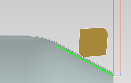
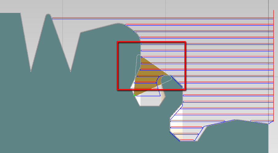
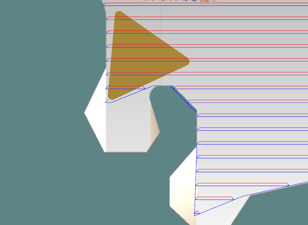
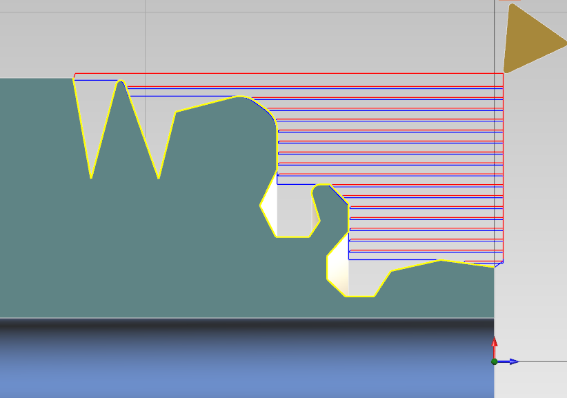
Tool Nose Radius Compensation
In Alexsys you don't have to bother about tool nose radius compensation.
Just set correct nose radius value and tool orientation in tool geometry dialog.

The toolpath is automatically compensated .
In below images you can see in blue ( and green ) the path the tool will follow, in order to create the programmed profile.


Reference
To better understand tool nose radius compensation on lathe you can search on google.
Or read here some good documentation :
http://cncprograming.blogspot.it/2011/07/tool-nose-radius-compensation-g40-g41.html
https://www.youtube.com/watch?v=kStjQkQPP6Q
http://www.webmachinist.net/toolradiuscomp.html
Import 2D CAD File DXF/DWG
- You can't import 3D shape
- It's better clean the cad file , leaving only the needed geometry before importing the file.
With Alexsys you can import 2D geometries from DXF / DWG files.
-
First select the plane you want to import the geometries you can select the XY or the XZ planes.
The XZ is the lathe plane.

-
From menu [FILE] -> [OPEN FILE]
Choose the file you want to import.
How to generate G-Code
To Generate G-Code , press this button from main Menu or press F8 from keyboard.

-
This window dialog is the next step , here you can define gcode output filepath.
Press G-Code or keyboard [ENTER] to generate GCode.
After generation the generated machine code will be opened into select text editor.

If may receive this error message :

This means that some operations toolpath are not valid.
Look at tree view you have some operation with error icon.
 Hover with mouse cursor the error icon to read message error.You need to solve all the issue before call g-code generation.
Cad Editor
Alexsys is not indented to be a full CAD system, but with the available tools is possible draw basic profiles or do some little edits to imported geometries.

Toolpath Simulation
Is possible get the simulation of generated toolpath with the command "Simulation"

Here the simulation side screen.
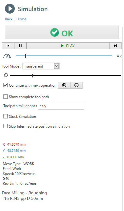
With simulation control you can single-step forward or backward.
Pause and continue simulation

With this control you can increment simulation speed. Drag the cursor with mouse

This slider stand for the current operation timeline, you can drag the cursor forward or backward.

Tool Mode : is possible show the tool with transparency or hide it completely
Continue with next operation : If checked, at the end of an operation simulation, the next operation is played. Otherwise the animation is stopped. Use the 2 button to go to next or previous operation manually.
Show complete toolpath : If checked, all the movements of current operation are shown .By default , just a the last part of the toolpath is visualized . The length of this visualized toolpath is determined by the property "Toolpath length".
Stock Simulation : If checked, the material removal simulation is shown. This option might impact on performance.
Stop on Collision : When a rapid collision is detected, the animation is paused on collision event. This option , is enabled only when the stock simulation is active.
Information : Current tool position and cut data parameter are visible in the lower part of the screen.
To get better performance on a PC with limited hardware you can :
- Disable [Stock Simulation] . Only movements are showed
- Enable [Skip Intermediate Position] . Only movements endpoints are visualized
It's not detected any collision between tool and fixture or tailstock.
Also very high feed work movements into stock are not detected.
Only rapid movements into stock are detected as collision.Basic Concepts
Here a brief explanation to understand the workflow to convert toolpath into gcode.
NC Program stages
You can consider the nc-program as a sequence of stages , each stage has it's own template :
- G-Code Header
- For each operation
- Tool Change
- Tool Approach
- List of movements that make up the toolpath, or in some cases macros (drilling, tapping, etc ..)
- Tool disengagement
- Operation Finalization
- G-Code Footer
Templates
Here an example of a template , which is nothing more of plain text .
Inside this text , you can see some word between curly brackets. These are the TAGS.
{EMPTY_LINE}
{LINE_N}
({OP_DESC})
{RADIUS_COMP_INFO}
({TOOL_LABEL})
T{TOOL_POS}M6
{NEXT_TOOL_POS}
{FEED_MODE}
S{SPEED_VALUE}{SPINDLE_ORIENTATION}
{ORIGIN}
{COOLANT_CODE}
Tags Dictionary
The tags are the variable values, here an example of a tags dictionary.
LINE_N = N5
TOOL_POS = 15
NEXT_TOOL_POS = 10
FEED_MODE = G98
SPEED_VALUE = 2387
SPEED_ORIENTATION = M3
ORIGIN = G54
COOLANT_CODE= M8
Output Final Code
From the combination of the single template and the tag dictionary, the output g-code will be created.
N5
(CONTOUR - ROUGHING)
(COMP COMPUTER - RADIUS COR VALUE 10)
(R390 D 20MM)
T15M6
T10
G98
S2387M3
G54
M8
...
The tag value will replace the {TAG_WORD} in the template.
Dictionary Convention
To facilitate understanding of the parameters available in the dictionary , it's been used a convention for naming tags.
Suffix _CODE :
These tags values are complete with both the char ( F, G, M) and numeric part ( 100, 0.3)
example :
{FEED_CODE} => F.3
{SPEED_CODE} => S100
Suffix _VALUE :
These tags values contain only the numeric part ( 100, 0.3) .
example:
{FEED_VALUE} => .3
{SPEED_VALUE} => 100
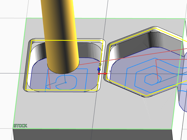
3D Stock Model
In Alexsys the 3D stock is modeled with defined machining operations.
From preference dialog you can choose how the model is created . From Menu -> Edit -> Preferences -> 3D Model Creation Mode
1 ) By Toolpath
The generated 3D model, is the effective result of the toolpath movements.
In this way you can see if there something wrong with generated toolpath.
For example, in the case below you can see the material left in the corner from the end mill machining. This is what you get on real machining.
[Simulation Stock Quality] is related to the stock in simulation context.
[Static Stock Quality] is related to the stock modeled in viewpoint context.
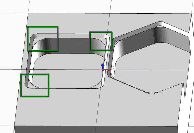
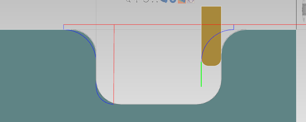
2 ) By Work Properties
This generation mode is usually faster , especially for simple 3D model, but it doesn't reflect the effective toolpath.
Some work machining like threading and engraving are not elaborated .
In the example below you can see the model is not considered the corner radius of the pocket. It's just used the profile and work parameter to model the stock.
Textbox integrated calculator
Every numeric textbox has an integrated expression solver.
This mean you can insert expression like " ( 6+6 ) * 2 ", and when you leave the textbox field, in the text box will convert it to 24 as result.

Unit Conversion
Is also possible unit conversion , from [mm] to [inch] and from [inch] o [mm] units.
Just insert [mm] or [in] suffix at te end of inserted value.
Example:
In a [mm] unit file instance, set as text " 1 in " or 1 inch in any numeric textbox .
The value will be converted in 25.4 mm .
Timeline
In the window application bottom , is visible the timeline control.

1) It's the time of current selected operations.
If you hover this label, you can see the timing grouped by setup, if you have multiple setup in your project.

2) Here it's a graphical representation of machining time of each operation.
The purpose of this graphic is too see at glance what operations are taking most of the machining time.
Every operation has a different color, if you hover it with mouse cursor you can see the related operation in the viewpoint.
Click on color bar to select related operation.
Manual Code
With [Manual Code] operation , is possible add manual text in output g-code program.

Load Template : Load existing gcode.
Description : It's the name of current template . It's used as identifier when you need to save , load or delete a template.
Insertion Mode :: Write only g-code : In output gcode related to this operation, you get the imputed text without any other command.
Insertion Mode :: Call Tool + Manual Code : In output g-code related to this operation , you get also the tool change and tool disengagement logic.
Save Template : Save the current text as template. You can find it in template list after this.
Delete Template : It will delete the related template from list.
G-Code Text : It's the manual g.code text you are going to add in output code.
Note : The "manual g.code" operation is just to add plain gcode to output text.
Simulation of this operation is not meant to be good , it will read only linear movements.
Macro , M-Codes , CRC compensation or other commands are not elaborated.Stock Materials
The purpose of having several stock material is to give the possibility to save different tool cut-data for the same tool.
Example :
With the same End-Mill :
-> if you are going to work mild steel , the software will select related cut data parameter for mild steel
otherwise
-> if you are going to work aluminium , the software will select related cut data parameter for aluminium
Default Material List
By default you have 3 material available:
- Mild Steel
- Stainless steel
- Aluminium
To open the material dialog, first you need to open tool table :
From Menu -> Edit -> Tools

then click [EDIT STOCK MATERIALS] from tool table.

The button is available only when you open tool window from menu.
When you open tool window in "Tool Selection Mode" this action it's not enabled
Below the MATERIAL LIST window.

Create New : Add a new material to the list. See below the properties you need to edit.
Delete : It delete permanently selected material. It not suggested delete materials after using it in some project.
Save And Close : Save user edits and close the window
Material Properties
Unique Id : This is an auto-calculated property. It's the combination of [Material Group] and [Material Grade] properties.
1) Is important have a different unique id for each material. This property is used to retrieve the cutting data parameters related to the material.
2) Don't change this id from existing material , since you are going to lose all the referenced cutting data .
Description : This is the description you are going to see in home treeview or in combo box in the tool store dialog.
Material Group : You can consider this as the material main category . The common group are P - M - K - N - S - H
Material Grade : For the same material group you can have different material grades. Insert the value in this field.
Material Group and Grades are used from tool builder to classification the various material of component part.
Specific Weight : Right now this property it's not used from the software. It's planned a method to give to the user the weight of the stock. So it will come in handy in the future.
Operations Logical Sort
In home treeview toolbar, is visible the Logical operation sort button.

When enabled , all the operation are keep sorted by logical flow of the machining logic.
So , for example, the centering operation comes before the drilling operation, the drilling operation comes before the tapping operation, the roughing operation comes before the finishing operation and so on.
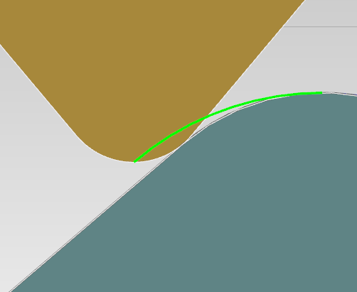
Plunge Angle Compensation
Is possible to compensate the machined profile based on tool plunge capabilities.
Sometimes you can import turning profile with pockets, by default no check are performed.
So you can have some scenario like in the image below, where the tool collide with profile.
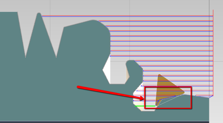
To overcome this problem is possible to select different plunge modes.
- Free
- By Tool Geometry
- Don't Plunge

Free mode
The profile are not manipulated and no check are performed , is the default mode.
By Tool Geometry
The profile is compensated with the max plunge angle of the tool , increased by 3° .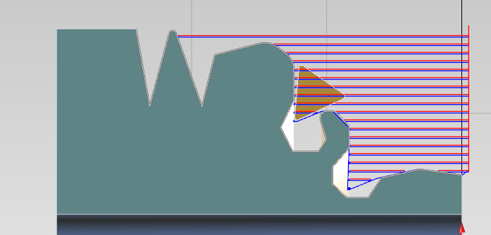
Don't plunge
In this mode , pocketing is not enabled. The profile is compensated in this way :
Edit plunge angle
You can adjust tool orientation from tool geometry parameter.
Enable [Edit Plunge Angle] and then edit the [Additional plunge angle]

Quick Fix Imported Geometry / Adjust imported geometry
Just after cad file import, a side screen with the most common edits will appear on the left screen.
You can open this screen also from MENU - >DRAW -> ADJUST IMPORTED GEOMETRIES
The applied changes will affect only selected entities.

Select all geometries : It select all the visible entities on the scene.
Clear selection : All the entities are de-selected
Invert selection : Selected entities will be de-selected and other way round
Change plane : Move the entities to XY or ZX PLANE
Scale : Entities will be scaled by selected factor. You can choose from common factor or define the value on your own
Rotate : Use the button to rotate selection of +90° or -90° . Otherwise insert a rotation value and press the check mark button.
Flip : Flip selection vertically or horizontally
Pick origin point : Move the entire selection , so the world coordinate zero , will be the selected point.
If you need advanced control on geometries , like linear or circular array creation , use the related tool under MENU->DRAW menu dropdown