Hydratight Setup
New System Setup
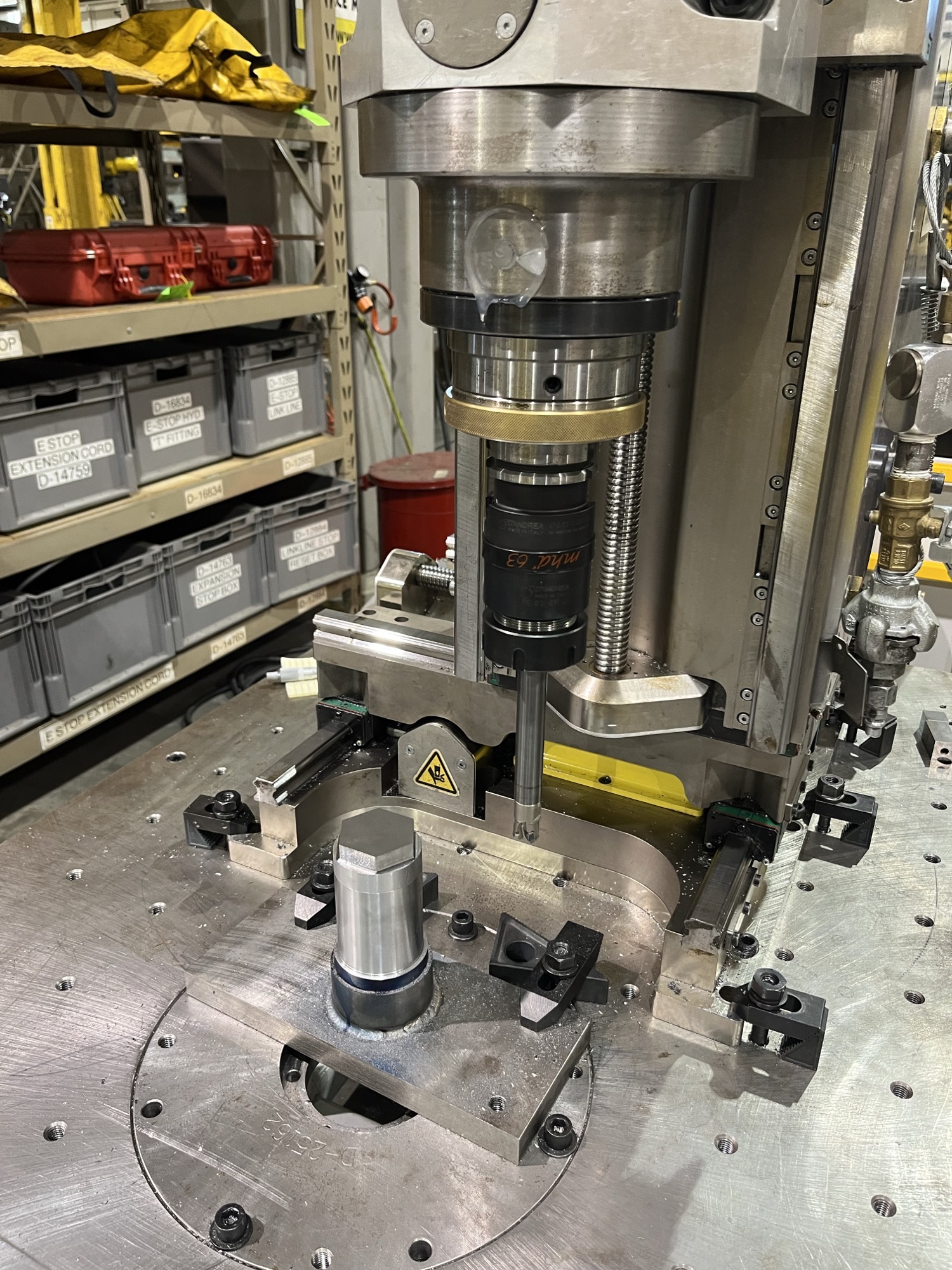
Click to open full size image. This is the mill that In-Place Machining bought from Hydratight, and is typical of the mills that Hydratight runs.
Settings
For new setups, start with the latest ini located here: M:\Production\Customer Backups\Hydratight_OEM\_Production Information\Master Control Files\Mach4 V2.0
Then run the standard Mach4 MachMotion Installer over the old ini.
For the spindle drive, use X15-02-25 and follow this document: https://support.machmotion.com/books/mm-production/page/x15-02-25-yaskawa-analog-and-digital-control-%28velocity-and-position%29 .
Drive Setup
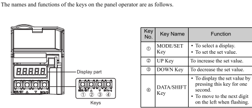
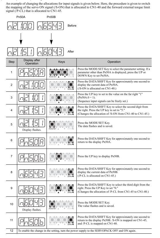
You need to change the Pn50A parameter in the X,Y,Z drives. If you open the black door on the front of each drive you will see 4 buttons.
Set Pn50A to 8021
Spindle Disable Feature
Wiring (Done by default on standard systems)
Follow these steps to update an existing machines wiring:
Turn off Power Supply and open the cabinet.
You need to remove the 0408 wire from the 5CR relay and the VFD.
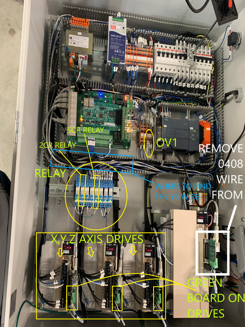
-
- There is a green circuit board on the front of the VFD and you need to remove the 0408 wire from the S03 port on that board.
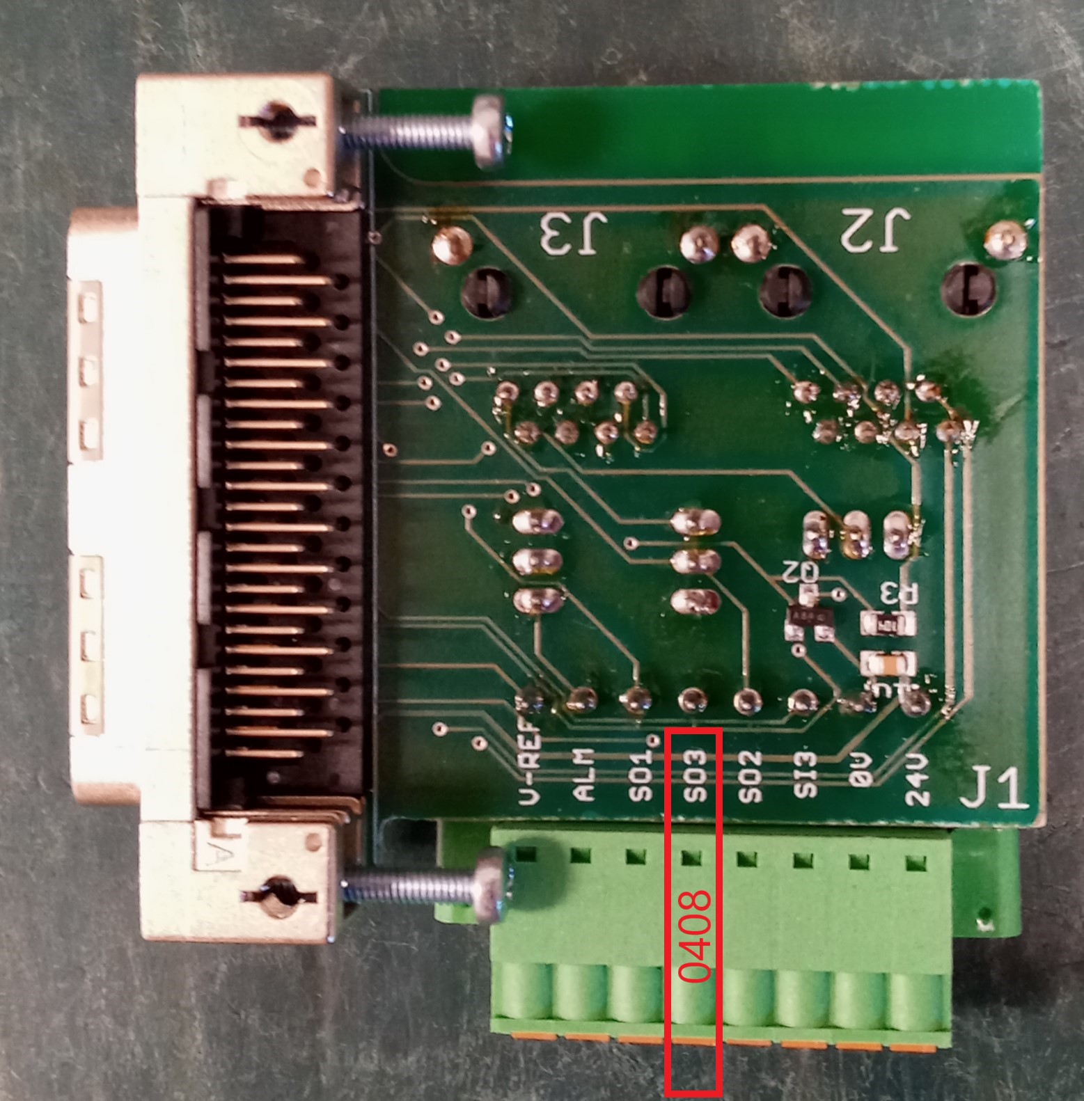
-
You need to remove the other end of the 0408 wire from the A1 port on the bottom of the 5CR relay.
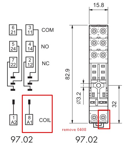
-
Heat shrink both of the exposed ends of the 0408 wire to prevent it from shorting out.
- There is a green circuit board on the front of the VFD and you need to remove the 0408 wire from the S03 port on that board.
Add the Y3 wire
There is a bundle of Yn wires coming from the Apollo motion controller down to the relay bank. Locate the Y0, Y1, Y2, wires that connect into the blue relays, and follow them back into the cable tray. Open up the shrink wrapped bundle of Yn wires to expose the unused leads.
- Locate Y3 and remove any heat shrink protecting the contact.
- Connect Y3 to the A1 port on the bottom of the 5CR relay.
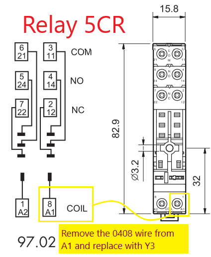
- Re-protect the remaining unused Yn leads with shrink wrap tubing, and place them back into the cable tray.
Connect the axes drives to the 2CR relay
- Next locate the green I/O board on the X axis, Y axis, and Z axis drives.
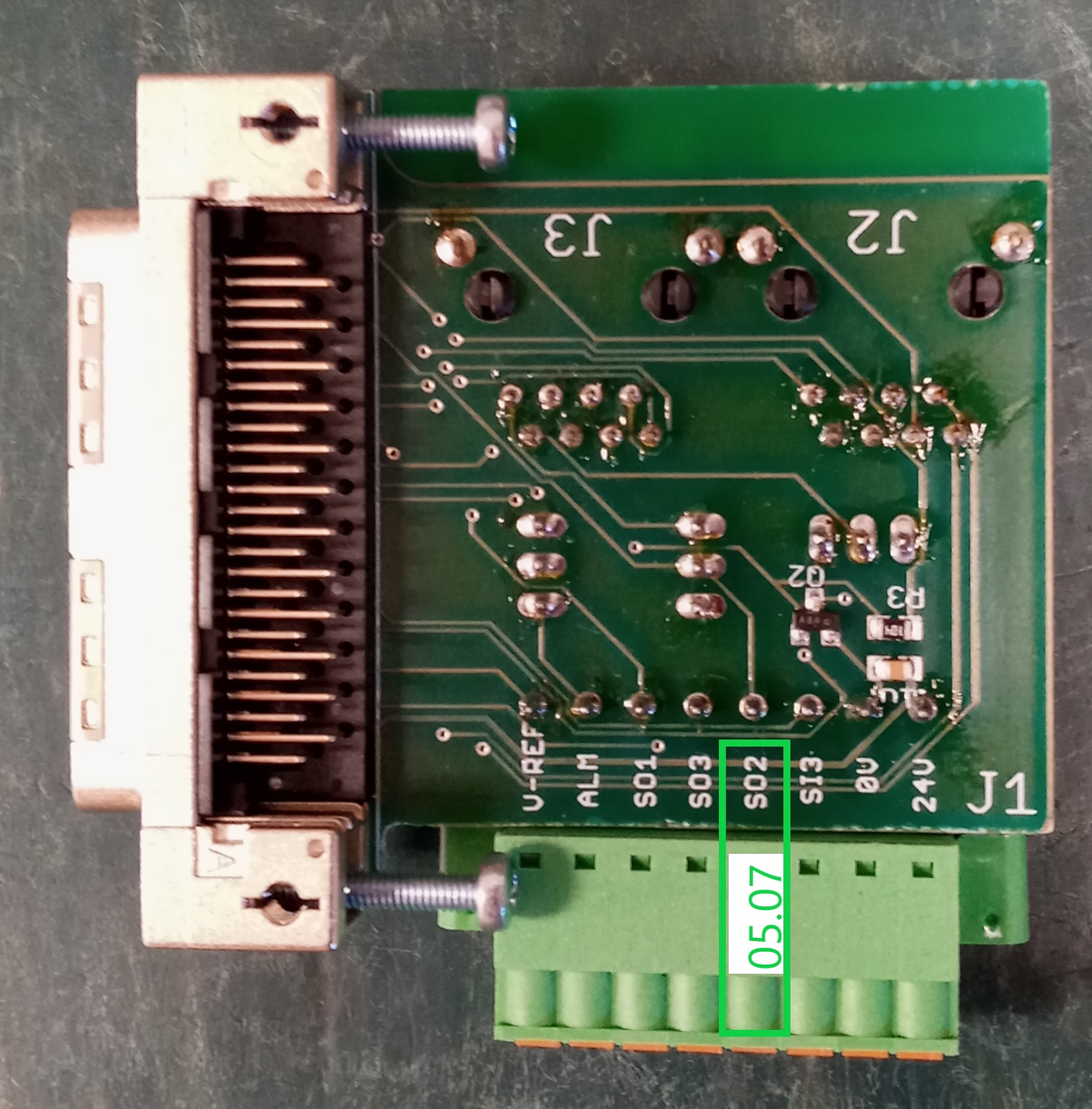
- Run a new wire (22awg or 0.64mm) from each of the 3 drives to the 2CR relay. On the drive, use the S02 position on the green boards. All three wires from the drives can go together into the top of 2CR relay. Use the Normally Open (NO) position. Label those wires 05.07 on all ends.
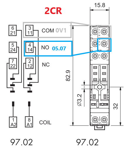
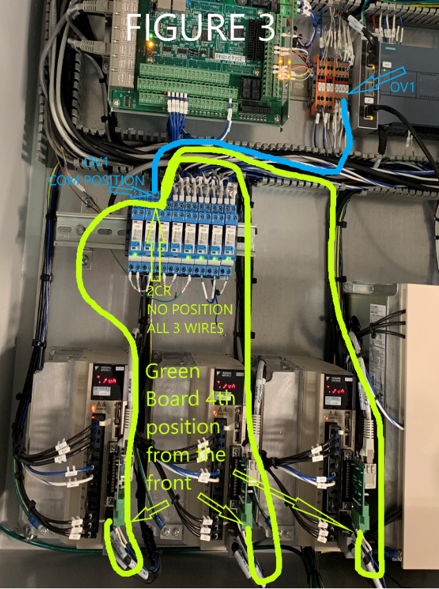
- Run a new wire (22awg or 0.64mm) from the 0V1 wire block to the COM position on the top of 2CR. Label both ends OV1.
Software Changes
To enable this on an existing machine, follow the procedure below.
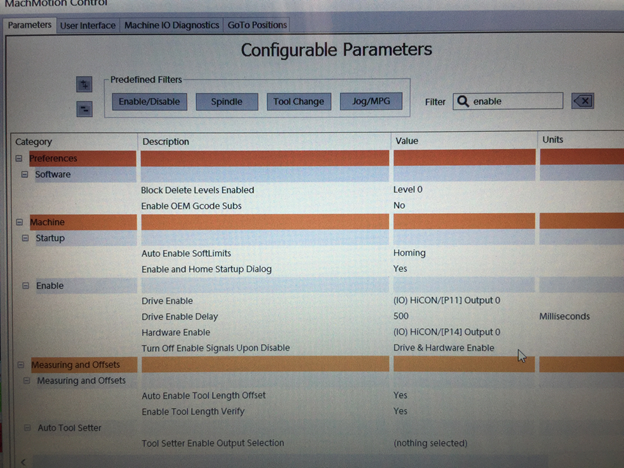
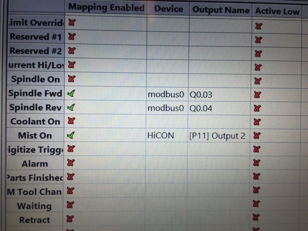
Set up enable signals as shown.
What is actually going on here is Y3 is wired to the Brake so Mach4 can control it separately from the drive. Port 14 output 1 or what is normally drive enable is ONLY used for Spindle Enable.
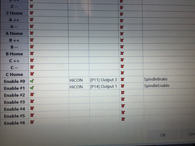
Un-map coolant On and disable it.
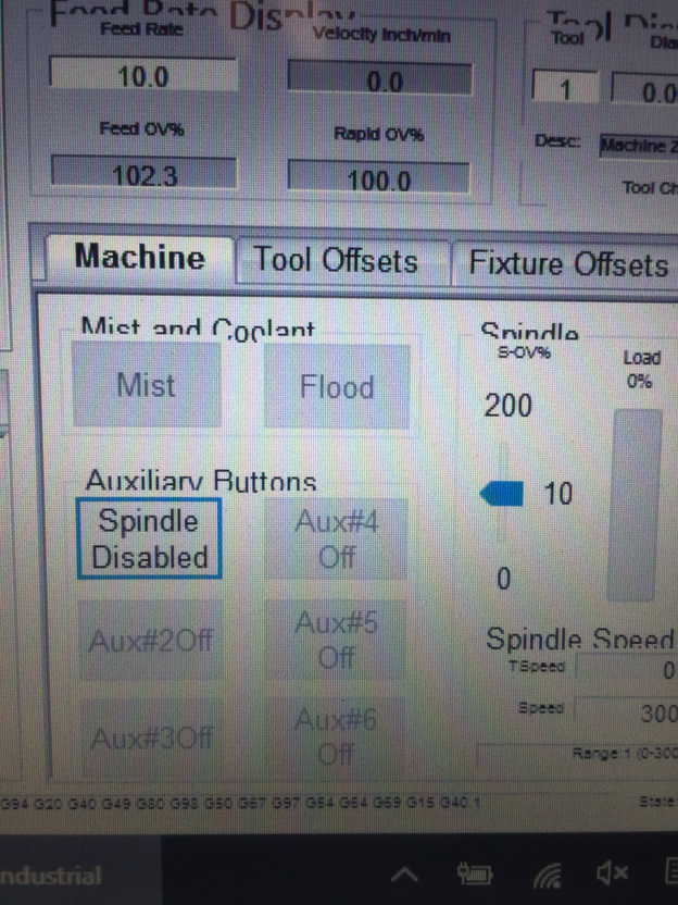
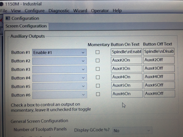
Setup Drive Enable as shown under Machine->Enable.