2000 Series Centerless Grinder Setup Manual (Rapidpath)
Below is the standard setup for any 2000 series centerless Grinder
Axis Setup
Axis Names

Axes Directions

- Grind Dress X Axis Traverse - 0.00 Is out away from the wheel towards the front and moving toward the wheel is positive.
- Grind Dress Y Axis Diamond - 0.00 Is out away from the wheel and moving toward the wheel is negative.

- Reg Dress Z Axis Traverse - 0.00 Is out away from the wheel towards the front and moving toward the wheel is positive.
- Reg Dress 4+ Axis Diamond - 0.00 Is out away from the wheel and moving toward the wheel is negative.
- Infeed (5 and 6 or B and C) - Reg wheel moving towards the grind wheel is infeed negative.
Comp Directions
- Grind Dress
- Comp In should make the dresser move toward the wheel the next time you cycle the dress cycle. When you press Comp In, the machine doesn't move. It only updates the grind dress offset which causes the Y axis value to increment.
- Comp Out should make the dresser move away from the wheel the next time you cycle the dress cycle. When you press Comp Out, the machine doesn't move. It only updates the grind dress offset which causes the Y axis value to decrement.
IO Setup
Outputs
| Name | Function | Configuration |
| Hydraulic Pump | Map it to the correct signal in MachMotion parameters |
Inputs
| Name | Function | Configuration |
| Hydraulic Pressure Okay | GMS - warning if hydraulics on (Output# 10) for 5 seconds | |
|
Function (Also description IO in Mach4) |
Safety Relay |
Configuration in Mach4 |
|
7201M - Hydraulic Pump (Q00.0) |
|
MM plugin - hydraulics |
|
7202M - Coolant And / Or Filter Pump (Q00.1) |
|
Config-> coolant??? |
|
7203M - Grind Wheel Dress Motor Contactor (Optional) (Q00.2) |
|
MM plugin - Grind wheel if used |
|
Q00.5 - Work Light (Above Safety Circuit) |
Above |
MM plugin - Work light |
|
Q00.6 - Unused (Above Safety Circuit) |
Above |
|
|
Q00.7- Unused (Above Safety Circuit) |
Above |
|
|
Q01.0- Unused (Above Safety Circuit) |
Above |
|
|
Q01.1- Unused (Above Safety Circuit) |
Above |
|
|
|
|
|
|
7501CR - Lube (Q08.0) |
|
MM plugin - lube - on with machine enabled; event |
|
7502CR - Grind Wheel Coolant (Q08.1) |
|
MM plugin - Grind wheel coolant |
|
7503CR - Reg Dresser Coolant (Q08.2) |
|
MM plugin - reg wheel coolant |
|
7504CR - Grind Dresser Coolant (Q08.3) |
|
MM plugin - grind dresser coolant |
|
7506CR - Grind Wheel Lube (Q08.4) |
|
PMC -> enable |
|
7507CR - Main Air (Q08.5) |
|
PMC -> enable |
|
7508CR - Unused (Q08.6) |
|
|
|
7509CR - Unused (Q08.7) |
|
|
|
|
|
|
|
7511CR - Grind Dresser Front (Q09.0) |
|
MM Plugin - centerless |
|
7512CR - Grind Dresser Back (Q09.1) |
|
MM Plugin - centerless |
|
7513CR - Grind Dresser Diamond (Q09.2) |
|
MM Plugin - centerless |
|
7514CR - Reg Dresser Front (Q09.3) |
|
MM Plugin - centerless |
|
7516CR - Reg Dresser Back (Q09.4) |
|
MM Plugin - centerless |
|
7517CR - Reg Dresser Diamond (Q09.5) |
|
MM Plugin - centerless |
|
7518CR - Unused (Q09.6) |
|
|
|
7519CR - Unused (Q09.7) |
|
|
Inputs
|
Function (Also description IO in Mach4) |
Active Low |
Configuration in Mach4 |
|
I00.0 - Unused |
|
|
|
I00.1 - Overloads Okay |
|
GMS - disable |
|
I00.2 - Air Pressure Low |
|
GMS - disable |
|
I00.3 - Way Lube Pressure Low |
|
GMS - disable |
|
I00.4 - Way Lube Level Low |
|
GMS - warning |
|
I00.5 - Coolant Filter Dirty |
|
GMS - disable |
|
I00.6 - Hydraulic Filter Dirty |
|
GMS - disable |
|
I00.7 - Grind Wheel Hydraulic Filter Dirty |
|
GMS - disable |
|
I01.0 - Coolant Flow Okay |
|
GMS - disable |
|
I01.1 - Hydraulic Pressure Okay / Bearing at Pressure |
|
GMS - warning if hydraulics on (Output# 10) for 5 seconds |
|
I01.2 - Reg Wheel Axis Drive Fault |
|
GMS - disable |
|
I01.3 - Reg Wheel Resistor Fault (Optional) |
|
GMS - disable |
|
I01.4 - Grind Wheel Resistor Fault (Optional) |
|
GMS - disable |
|
I01.5 - Unused |
|
|
|
|
|
|
|
I08.0 - Grind Dresser Front |
|
MM Plugin - centerless |
|
I08.1 - Grind Dresser Back |
|
MM Plugin - centerless |
|
I08.2 - Reg Dresser Front |
|
MM Plugin - centerless |
|
I08.3 - Reg Dresser Back |
|
MM Plugin - centerless |
|
I08.4 - Wheel Guard |
|
GMS - warning |
|
I08.5 - Wheel Balancer Fault |
|
GMS - disable |
|
I08.6 - Unused |
|
|
|
I08.7 - Unused |
|
|
|
I09.0 - Grind Dresser Speed Low Push Button |
|
MM Plugin - centerless |
|
I09.1 - Grind Dresser Speed Medium Push Button |
|
MM Plugin - centerless |
|
I09.2 - Grind Dresser Speed High Push Button |
|
MM Plugin - centerless |
|
I09.3 - Grind Dresser Out Push Button |
|
MM Plugin - centerless |
|
I09.4 - Grind Dresser In Push Button |
|
MM Plugin - centerless |
|
I09.5 - Grind Dresser Front Push Button |
|
MM Plugin - centerless |
|
I09.6 - Grind Dresser Back Push Button |
|
MM Plugin - centerless |
|
I09.7 - Dresser Coolant Flow Okay |
|
GMS - disable if coolant on for 5 sec |
Hydraulics

Regulating Wheel Setup
Servo Spindle
Setup Rapidpath as a servo spindle.
Note: Reg wheel should always be incremental, even if you have absolute encoders.

Set the spindle mode to Auxiliary.
Set the Auxiliary Max Motor Speed (RPM) to Rated Motor Speed.

Setup Reg wheel settings as shown here:
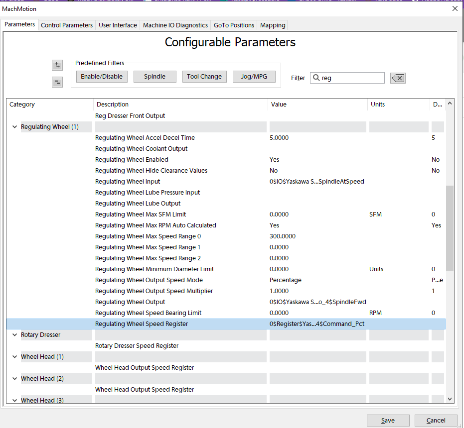
Set Max Speed Range 0 to the max RPM.
Command the regulating wheel to go (ideally the max RPM for Speed Range 0) and use a tachometer to confirm it goes the correct speed. If it doesn't, calculate the new Regulating Wheel Max Speed Range 0 as follows:
Actual RPM / Commanded RPM * Range 0 = New Regulating Wheel Max Speed Range 0

Load Meter
Setup the load meter by configuring the Sub Spindle.


Grind Wheel Setup
Yaskawa VFD Setup
Setup the VFD in Rapidpath. Auxilary Max RPM is not used (it can be set to 1000 by default).

Map the IO


Setup the grind wheel as follows:

Set the Grind Wheel Max Speed Range 0 to the max RPM the actual grind wheel should go at the max frequency.
Now test the grinding wheel speed. Enter in a speed command and monitor the actual speed with a tachometer. Make sure your Max Wheel RPM is high enough to allow the commanded speed you want to command.

If it isn't correct, calculate the new Max RPM as follows:
Actual RPM / Commanded RPM * Grind Wheel Max Speed Range 0 = New Max RPM.
Now set the Grind Wheel Max Speed Range 0 to the New Max RPM.
Load Meter

Grind Wheel Speed Calibration
- Find out what the max speed they want to command on the wheel is
- Set the "Yaskawa V1000 Auxiliary Control Max RPM", "Grind Wheel Max Speed Range 0", and the on-screen maximum grind wheel speed to this value.
- Command a speed of half of the maximum RPM and get a tachometer reading to see if it is going too slow or fast compared to commanded. This is necessary so we don't over-speed and explode the wheel.
- If the actual speed is faster than commanded, jump to step 5, then return to step 4.
- Command the full speed and record the tachometer reading.
- Set "E1-04 Max Output Frequency" to its current value multiplied by commanded speed / actual speed.
Hz = "Yaskawa V1000 E1-04 Max Output Frequency" parameter
NewHz = CurrentHz * CommandedSpeed / ActualSpeed
Auto Loader
To enable the Auto Loader, set the pound variable AutoLoaderEnabled in the gcode file to 1. Also, setup user button 6 to set the pound variable AutoLoaderEnableButton to 1 or 0 to activate it or turn it off.
Grind Settings
If you are working with Precision Punch make sure that you are using diameter mode.
You can set the the parameter in the Machmotion plugin to 1 for diameter and 0 for incremental

Part Loader Setup
"Part Loader Enabled" - Change to "Yes"
"Part Loader Load ..." parameters are ONLY for the action of loading a part into the machine.
"Part Loader Unload and Load ..." parameters are ONLY for the cycle of both unloading a finished part and then loading a new part.
"Part Loader Unload ..." parameters are ONLY for the action of unloading a finished part.
*Kickers have a separate parameter and should not be mapped to any "Part Loader Unload ..." parameters.*
The system is designed for complex loading assemblies and requires some manipulation to work on simpler part loaders.

Part Loader Parameters
| Parameter Name | Description |
Required |
| Enabled | Enables or disables the loader function | No |
| Type | Method I/O, PLC Sequence, Subroutine | No |
| Unload On End Of Cycle | No | |
| Load Request Output | Output | Yes |
| Load Request Confirm Input | Input | No |
| Load Complete Input | Input | Yes or In-Cycle Input |
| Load Complete Confirm Output | Output | No |
| Unload And Load Request Output | Output | Yes |
| Unload And Load Request Confirm Input | Input | No |
| Unload And Load Complete Input | Input | Yes or In-Cycle Input |
| Unload And Load Complete Confirm Output | Output | No |
| Unload Request Output | Output | Yes |
| Unload Request Confirm Input | Input | No |
| Unload Complete Input | Input | Yes or In-Cycle Input |
| Unload Complete Confirm Output | Output | No |
| Wheels In Position Output | On when wheels are at the load position |
Yes |
| In-Cycle Input | Should be on while the loader is in cycle |
No |
| Alarm Input | Creates Alarm and opens dialog | No |
| Empty Input | Creates Information dialog | No |
Load Part Diagram

Unload Part Diagram

Part Loader Alarm
The Part Loader has a parameter named "Part Loader Alarm Input" that can be mapped to an input signal or IO and when the input goes high an Alarm will be generated.
It also supports a OEM Parameter Register named "Part Loader Alarm Message Register" that is used as a mapping register that holds the path to a register that will hold the alarm code. The loader would need to write the alarm code to the register to be displayed.
There is also a register named "Part Loader Alarm Messages" that can hold messages in CSV format and show custom string messages based on the number written to the "Part Loader Alarm Message Register". If this is setup the Alarm message will include the messages from the parameter.
Example of the CSV string for parameter "Part Loader Alarm Messages"
100,Alarm Message 100
101,Alarm Message 101
102,Alarm Message 102
103,Alarm Message 103