1000 Series Lathe Control Operating Manual
![]()
1. Introduction
1.1 Control Startup
To open the control software double-click on the Lathe profile icon on the desktop.
![]()
Figure 1 – Control Icon
1.2 Overview
This manual gives the process for basic operation of a Lathe using the MachMotion control. The screen is shown below, followed by a brief summary of the different sections of the screen.

Figure 2 – STANDARD Control Screen Overview
For a quick reference, the description of each zone is located below.
- The tool path window shows the path the tool will take when a G-Code file is loaded. G-Code line number display (can also show percentage complete with setting change) and part counter display.
- Unlock the screen to access certain features/settings. Use DRO mode to measure or run in manual mode. DRO mode has no effect on fixture offsets.
- The axis DROs show the current location and homing state. The axis label LEDs and the actual DROs turn green when the axis is homed. It also shows the remaining travel distance to complete the current line of G-Code and the current machine coordinates. The [GoTo Position] button allows you to move to a preconfigured position.
- Tool, feed rate, and spindle display settings.
- Spindle control and status, Mist & Coolant, and Auxiliary Buttons. Change between tabs for offsets and settings.
- The Control section is used to Enable/Disable system, Start and Stop programs, and Feed Hold. Reset will rewind the program and return to the default state of G-Code settings.
- G-Code control and other functions
- View current/last status message. Click [History] to view status messages and clear status line.
- Displays current G-Code modals and the state of the control.
2. Homing
To home the lathe, begin by enabling the system (Figure 2 #6). Click [UnLocked] button (Figure 3). To home all axes press the [Home All] button. Each axis can also be homed using the individual axis home buttons. Once an axis has been homed, the axis LED display will be green.

Figure 3 - LATHE HOMING
3. Programmed Movement
3.1 MDI
To command a movement using the MDI feature, press the MDI tab.

Figure 4 - MDI TAB Selection
Enter the desired G-Code command into the field and press [Cycle Start] to execute the command(s). The up/down arrow buttons will scroll through the history of cycled commands.

Figure 5 - Example MDI Command
3.2 G-Code
The primary method of commanding motion is using G-Code files. G-Code files can be hand written, generated by a wizard, or generated from CAD files using a CAM program.
3.2.1 G-Code File Controls

Figure 6 - G-Code Controls
- Cycle Start – Starts a loaded G-Code file
- Feed Hold – Pauses a running G-Code file which can then be restarted by pressing Cycle Start
- Cycle Stop – Stops a running G-Code file or other commanded movement
- Reset – Rewinds a loaded G-Code file to the beginning and resets G-Code modals to default configuration
- Load – Opens a file browser to select an existing G-Code file
- Recent – Opens a selection window with the ten most recent run G-Code files
- Edit – Opens a loaded G-Code file to allow easy editing
- Close – Closes the loaded G-Code file
- M1 Optional Stop – Stops program with M1 command
- Single Block – Run the G-Code line by line
- Block Delete – Ignores designated lines within the G-Code file
- Run From Here – Run the loaded G-Code file starting at selected line
3.2.2 Running a G-Code File Example
To run a G-Code file, follow the steps below:
- Press the [Load] button (Figure 6) then select a G-Code file and press [Open]
- Jog the machine to the work piece zero point
- Zero the Z by selecting [UnLocked] and then [Zero Z] (Figure 7)
- Before running G-Code, it is good practice to go back to [Locked] mode. All offsets are saved when [Locked] is pressed.
- Press [Cycle Start] to run the program (Figure 6)
- If it is necessary to stop in the middle of a program to inspect the part press [Feed Hold] (Figure 6)
- If it is necessary to end a program before it has completely run press [Cycle Stop] (Figure 6)

Figure 7 – Zero the axes
3.2.3 Running a G-Code File with the Single Block Option
If it is necessary to run a G-Code file line-by-line, follow the steps below:
- Click the [Single Block] button (Figure 6)
- Press [Cycle Start] button to begin the file (Figure 6)
- The line will run and then enter feed hold.
- To run successive lines, continue pressing [Cycle Start]
- When finished running lines, press [Single Block] to put it back in normal run mode
3.2.4 Block Delete Option
The Block Delete option (Figure 6) allows for specially marked lines to be ignored when running a G-Code file. Consider the following:
N1 M3 S2000
N2 /G00 G91 Z-1
N3 G00 G91 X4 Y5
N4 /4 G01 G91 Z3
N5 /M00
N6 G01 G91 Z5
N7 /8 M5
N8 M30
With the Block Delete options selected as noted in Figure 8, the N2, N5, and N7 lines would be ignored.

Figure 8 – Zero the axes
3.2.5 Running a G-Code File with the Run From Here Option
If for whatever reason a program needs to be started in the middle, use the Run From Here feature by following these steps:
- Use the Up/Down arrows in the G-Code file window to select the line to start from (Figure 6)
- Press the [Run From Here] button (Figure 6)
- Select the [Change to Needed Tool] button if applicable (Figure 9)
- Enter desired value in the Feed Rate field (Figure 9)
- Select axis to move and press [Move Selected] button (Figure 9) to move the axis into position
- Select desired Auxiliary Settings and press [Turn On Selected Auxiliaries] button (Figure 9)
- Press [Cycle Start] to begin the file at selected starting line (Figure 6)

Figure 9 – Run from here
3.2.6 Tool Path Screen
Below are the controls to manipulate the tool path screen:
- Zoom – right click with the mouse and move mouse up/down
- Rotate – left click with the mouse and rotate the part by moving the mouse
- Pan – press Ctrl on the keyboard and left click with the mouse, then pan by moving the mouse (one-hand control option is to use left and right mouse click and move the mouse. No Ctrl press needed)
3.3 Advanced
The Advanced tab has various settings and axis details for the G-Code file to be run as well as options for the tool path display.

Figure 10 - Advanced Controls
3.3.1 Dry Run
The Dry Run option will process the G-Code file without turning on Mist or Coolant.
3.3.2 M-S-T Lock
The M-S-T Lock mode prevents the Mist, Spindle, and Tool Changes from activating when running a G-Code file (ignores M-, S-, and T-Codes).
3.3.3 Regen Tool Path
Clicking the [Regen Tool Path] button regenerates the Tool Path window display.
3.3.4 Show Boundaries
Clicking the [Show Boundaries] button displays a dotted line around the area of range of travel determined by values set in soft-limits.
3.3.5 Jog Follow
Jog Follow sets the tool path screen to keep the current position in the range of view
4. Tools and Tool Offsets
4.1 Tool Offsets
All tool offsets are shown in the tool offsets tab (Figure 2 #5). To edit the offsets, press [UnLocked] (Figure 3).

Figure 3 - Tool Offsets
Tool offsets can be set or viewed in the in the Tool Offsets (Figure 13) by pressing the [Show Tool Table] (Figure 3).
4.2 Tool Setup
To setup the tool offsets, follow the steps below:
- Change the tool number to the number for the new tool
- Put the new tool in the spindle
- Open the Tool Offsets (Figure 13) by pressing the [Show Tool Table] (Figure 3)

Figure 13 - Tool Table
- Enter the Tip Rad of the tool
- Enter in the Post as Front or Rear
- Select your tip according to the following options


- Move the machine to a known location in the X axis on the part
- Enter in the known X location in the X Setup Position field
- Go to the Tool Offset tab (Figure 11)
- Press the [Calculate X Offset] button to save the X tool offset
- Move the machine to a known location in the Z axis on the part
- Enter in the known Z location in the Z Setup Position field
- Press the [Calculate Z Offset] button to save the Z tool offset
- Repeat steps 1-9 for each additional tool

Figure 11 - Tool Window
4.3 Tool Display
The current tool settings are shown in the main Tool Display.

Figure 4 Tool Display
- T – Current tool – the first two digits refer to the tool and the second two refer to the offset?
- Picture – shows the current tip of the tool
- Tool Post – shows which tool post the tool is connected to – front, rear, or not defined
- Desc – shows the description of the current tool
4.4 Tool Wear
As tools wear, enter in X and Z wear accordingly in the main Tool Offset tab or by pressing the [Show Tool Table] (Figure 3) to open the Tool Offsets window (Figure 13).
5. Spindle Control
5.1 G-Code Spindle Control
The spindle is controlled through G-Code using the M-Codes M3 (Clockwise), M4 (Counterclockwise), and M5 (Off). To control the spindle speed in RPMs an S word is added.
For example, M3 S2000 would turn the spindle on in the clockwise direction at 2000 RPM.
5.2 Manual Spindle Control
To control the spindle separately from G-Code use the spindle control on the Machine screen. The [Spindle FWD] turns the spindle on clockwise and the [Spindle REV] turns the spindle on counterclockwise.

Figure 14 - Spindle Control
The following spindle settings are also shown on the Machine tab:
- G50 Speed Limit – the maximum RPM the spindle can move with the current G50 setting
- Range – Pulley number selected and speed range
5.3 Spindle Display
The current spindle settings are shown in the main Spindle Display.

Figure 5 Spindle Display
- S – Commanded Speed
- Speed OV – Spindle Override Percentage
- rpm or ccs – the spindle speed in the current mode
- Load – % of the load of the spindle. This also is shown in the horizontal gauge.
Constant Surface Speed
Constant surface speed is a spindle mode where the speed of the spindle changes based on the current X diameter position. The speed will increase as the X position goes to zero and the speed will decrease as the position moves away from centerline. This variation in speed will keep a constant amount of material moving under the tool tip. This mode produces superior finishes on the part.
Constant surface speed is turned on with G96. The current spindle speed will be interpreted as surface feet/minute while in G20 and surface meters/minute in G21. To leave constant surface speed mode, use G97 to return to RPM mode.
When using constant surface speed, it is important to have a G50 (spindle speed cap) defined. This prevents the spindle from overspeeding as the diameter goes to zero.
6. Machine Output Control
6.1.1 Mist
[Mist] turns on and off the Mist control (Figure 14).
6.1.2 Coolant
[Coolant] turns on and off the Coolant control (Figure 14).
6.1.3 Chuck
[Chuck] turns on and off the Chuck control (Figure 14).
6.1.4 Tailstock
[Tailstock Backwards] turns on and off the Tailstock control (Figure 14).
7. Fixture Offsets
All G-Code files have their own coordinate system. In order to allow parts to be located on the table at any desired location, the part offset can be defined to adjust the actual location of the part on the table.
Part offsets can be defined and saved using G54-G59P120. The functionality is designed to allow different tooling setups to have predefined zero points to allow for streamlined setup.
You can view the fixture table and change the values directly by clicking the [Show fixture Table] button. The values can also be set by using the MDI command to select the G-Code number for the fixture offsets to be stored in. Once the machine is at the desired zero position, zero Z by pressing the [Zero Z] button.

Figure 15 – Fixture Offsets
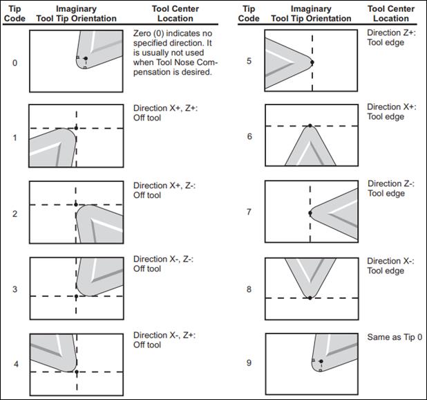
8. Turn Tip Types
The tip type (usually represented by a number) expresses the direction and useful paths of travel that a particular tool can cut. Most tips are "pointed" in a particular direction and have a limited angle at which they can cut. (There are no practical omnidirectional cutting tools on a lathe.) The tool tip type indicates which axis/axes you can cut along. The tip type also determines how tool nose compensation is applied. (See Lathe Tool Nose Radius Compensation for more details about compensation.)
In the following diagram, each tool type is shown, with the direction of X and Z where the tool is "pointing" and the cutting direction(s) indicated by the dotted lines.
i. Tool Tip Type defines the orientation in which a tool was zeroed, as if you were looking down onto the top face of the probe.
ii. Turning and Facing Tool: Tip Type 3
iii. Drills: Tip Type 7
iv. Part Off Tool (Zero on TSS): Tip Type 4
v. Part Off Tool (Zero on HSS): Tip Type 3
vi. Boring Bar: Tip Type 2
In this diagram, +Z is to the right, and +X is up (the same as in the previous diagram).
(Image Source: CNC Programming Handbook, 3rd Ed.; Peter Smid; p276)
These diagrams are for a rear-turret lathe. Some diagrams you may find will look (vertically) reversed because they are describing orientations for a front-turret lathe.
Turn Operations and Tip Types
Machinists will frequently associate tip types with types of turning.
- Turning
- cutting surface is in the -X direction
- tip types: 2, 6, 1
- Boring
- cutting surface is in the +X direction (i.e. hollowing out the inside of something)
- tip types: 3, 8, 4
- Facing
- cutting surface is in the -Z direction (i.e. removing material from the end, or "face," of the work piece)
- tip types: 2, 7, 3
- Back Facing
- cutting surface is in the +Z direction (i.e. removing material from an "inside face" of a part)
- tip types: 1, 5, 4
Resources
- CNC Lathe Resources (mae.ufl.edu)
- Tool Probing / Zeroing (mae.ufl.edu)
- Lathe Tool Orientation (linuxcnc.org)
- Tool Nose Radius Compensation (cncprogramming.blogspot.com)
- Cutter Radius Compensation (infosys.beckhoff.com)
- Tool Nose Radius Offset (pp. 275-278; CNC Programming Handbook, 3rd Ed., Peter Smid)
- Machine Type Operations (llbc.edu)
9. Appendix
9.1 Start-Up Procedure

Figure 16
Warranty Information
MachMotion warranty policy is subject to change. Updated information is available at our website:
https://machmotion.com/warranty
The MachMotion Team
http://www.machmotion.com
14518 County Road 7240, Newburg, MO 65550
(573) 368-7399 • Fax (573) 341-2672