2000 Series Mill/Router Operating Manual
![]()
Introduction
Overview
This manual gives an overview for the basic operation of the MachMotion Mill and Router controls. The screen is shown below, followed by a brief summary of the different features of the screen. The numbers shown in the screenshot refers to a brief description below the image.
Control Startup
To open the control software, double-click on the profile icon on the desktop.
![]()
Control Screen Overview
Gcode Tab
.jpg)
- Tool Path
- Regen ToolPath - Refresh the toolpath of the gcode
- View Top - Top view of the part
- View ISO - Side view of the part
- File
- Recent - Load a recently loaded gcode program
- Load - Load a program from the computer or flash drive
- Edit - Edit the code that is loaded into the software
- Close - Close the gcode that is currently loaded in the software
- Control
- Cycle Start - Starts the gcode from from the beginning of the part
- Feed Hold - Pauses the gcode program and keeps the spindle running
- Cycle Stop - Stops the gcode program from running
- Reset - Resets the alarm and also enables the machine
- Status
- Status - Displays any current messages (Home All Pressed, Cycle Start Pressed, etc.)
- State - Displays the current state of the machine (Run, Feedhold, etc)
- Cycle Time - Displays how long the gcode has been running
- Date - Date and time of the timezone of the control
- DROs (Axis Digital Readouts)
- MDI - Opens up a window that allows for gcode commands
- Viewing Part - Shows the part coordinates or machine coordinates of the machine
- Active Modals
- Active Offset - Shows the current active fixture offset (G54, G55, etc)
- Tool Display
- T - The current tool number selected
- Next Tool - The next tool that the gcode will need
- Diameter - Diameter of the tool
- Length - Length of the tool
- Feedrate Display
- F - The current feedrate commanded
- Feed OV - The current Feedrate Override utilizing the Feedrate Override knob on the operating panel (0-200%)
- Rapid OV - The current Rapid Override utilizing the Rapid Override knob on the operating panel (0-200%)
- Spindle Display
- S - The current spindle speed
- TSpeed - The current spindle speed feedback
- FWD - Turns on if the spindle is moving Forward
- REV - Turns on if the spindle is moving in Reverse
- Spindle OV - The current spindle override utilizing the spindle override buttons on the operating panel (0-200%)
- Spindle Load - The current spindle load utilizing the spindle speed feedback
- Range - Displays the current spindle range (spindle pulley)
- Advanced
- Single Block - If active the software will go line by line through the gcode when you press the cycle start button
- Block Delete - Deletes the block of gcode that is selected with / or /0-9 at the beginning of the line. Filter for "block" in the MachMotion parameters to turn on the /0-9 levels option.
- Part Counter - Displays the number of parts that the machine has produced
- M1 OPT Stop - If active the software will stop at any M1 commands in the gcode program and waits for cycle start
- Alexsys - Opens up the conversational assistant Alexsys in another window
- Dry Run - If active the software will ignore all mist or flood commands
- M-S-T Lock - If active the software will ignore all Macro codes, Spindle codes and Tool commands
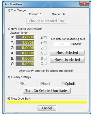
Run From Here\File Resume:
- Use the Up/Down arrows in the gcode file window to select the line to start from
- Press the [Run From Here] or [File Resume] button
- Select the [Change to Needed Tool] button if applicable (See Image Below)
- Enter desired value in the Feed Rate field (See Image Below)
- Select axis to move and press [Move Selected] button (See Image Below) to move the axis into position
- Select desired Auxiliary Settings and press [Turn On Selected Auxiliaries] button
- Press [Cycle Start] to begin the file at selected starting line File Resume - If selected this will start the program at the selected gcode line and resumes the file
- Collapse v - If selected this will minimize the Advanced buttons

Tools Tab

- Edit
- Edit Offsets - No offset changes can be made unless this value is yellow. It also displays the zero buttons near the DROs to the right.
- Tools
- Tool Table - View and edit tool table
- Pockets
- Register Tools - Register and save tools
- Calibrate
- Tool Setters - Select this to add or remove a tool setter. For more information, follow this link: https://support.machmotion.com/books/cnc-controls/page/creating-tool-setters---2000-series
- Tool Life Management - Will be added in the future
- Jump to Tool Number
- 1,2,3,4 etc. - Tool number (Tool change). Just press the button and the tool will change.
For 7-13 see the [Gcode Tab] above for more details
Fixtures Tab
Manual Setup

- Edit
- Edit Offsets - View and edit fixture offsets
- Fixtures
- Fixtures Table - View and edit fixture table (G54, G55, G56, etc.)
- X/Y Edge Finder Offset
- X+ - Zeros the X + offset
- X- - Zeros the X - offset
- Y+ - Zeros the X+ offset
- Y- - Zeros the Y- offset
- Edge Finder Diameter - This is the diameter of the edge finder used to calculate the new offset based on the zero button pressed above.
- Fixture Offsets
- X, Y, Z, etc. - Shows the currently loaded offset.
- Rotary Axis
- X,Y, Z -
For 7-13 see the [Gcode Tab] above for more details
Probing Setup

This tab is used to setup your part or measure a part. See this link for more information: https://support.machmotion.com/books/software/page/machmotion-probing-wizard .
Service Tab
Maintenance Tab

- Limits
- Soft Limits - Toggles software limits on or off
- Limit Override - Toggles to allow for the machine to move off a limit switch
- PLC
- Reset Pocket - Only used for tool changers.
- PLC Sequence -
- Enable
- Disable - Toggles if the machine is enabled or disabled
- Settings
- Interface Config -
- Motion Controller - Opens the plugin for the Motion Controller
- Screen Config - Edit the screen layout
- Industrial Theme -
- Toggle Menu - Turns the menu on or off
- Compile Scripts - Refreshes (recompiles) programming scripts
- Homing
- Home X - Homes the X axis
- Home Y - Homes the Y axis
- Home Z - Homes the Z axis
- Home All - Homes all axes
- Support
- Remote Support - Starts a remote support session with MachMotion Technical Support
- Support - Opens up the online MachMotion Support Library
- Updates - Checks for updates for MachMotion Software
- History - Views status history and alarms
- User
- Logout - Logs out of the Windows username
- Power - Closes the MachMotion software properly, and runs the Windows shutdown procedure.
For 7-13 see the [Gcode Tab] above for more details
Dashboard Tab

The Dashboard is used to make the control just the way you want it! For more information, see this link: https://support.machmotion.com/books/mach4-control-features/page/2000-series-commands-function-buttons-and-dashboard .
Machine I/O Tab

This tab is used for diagnostics and shows all your machine IO.
Homing
To home the machine, begin by pressing the [Reset] button. Then navigate to the [Service/Maintenance] tab and press [Home All]. There is an optional parameter to prompt the user to home the machine on startup.
Programmed Movement
MDI
To command a movement using the MDI feature, press the [MDI] button.
Enter the desired gcode command into the field and press [Cycle Start] to execute the command(s). The up/down arrow buttons will scroll through the history of cycled commands. Click the [X] or the [MDI] button to close the MDI window.

Gcode
The primary method of commanding motion is using gcode files. Gcode files can be hand written, generated by a wizard, or generated from CAD files using a CAM program.
Toolpath Screen
Below are the controls to manipulate the tool path screen:
- Zoom – Right click with the mouse and move mouse up/down or using the scroll wheel on the mouse
- Rotate – Left click with the mouse and rotate the part by moving the mouse
- Pan – Press and hold [Ctrl] on the keyboard and left click with the mouse, then pan by moving the mouse (one-hand control option is to use left and right mouse click and move the mouse. No [Ctrl] press needed)
Tools and Tool Offsets
See the Offset tab above.
Spindle Control
Gcode Spindle Control
The spindle is controlled through gcode using the M-Codes M3 (Clockwise), M4 (Counterclockwise), and M5 (Off). To control the spindle speed in RPMs an S word is added.
For example, M3 S2000 would turn the spindle on in the clockwise direction at 2000 RPM.
Manual Spindle Control
To control the spindle separately from gcode use the spindle control on the operating panel. The [Spindle FWD] turns the spindle on clockwise and the [Spindle REV] turns the spindle on counterclockwise.

The following spindle settings are also shown on the Spindle tab located in Configure -> Control -> Spindle:
- G50 Speed Limit – the maximum RPM the spindle can move with the current G50 setting
- Range – Pulley number selected and speed range
Spindle Display
The current spindle settings are shown in the main Spindle Display.

- S – Commanded Speed
- Spindle OV – Spindle Override Percentage
- Spindle Load – % of the load of the spindle.
- Range – Current Pulley Selected
Spindle Warm Up
Mach4 has the ability to setup a Spindle Warm Up procedure for machines.
To be able to configure this go to Control->Plugins->MachMotion and then search for Spindle Warm Up.
Below is an example screen for the Spindle Warm Up settings.

| Spindle Warm Up Off Time Trigger | How long do want the spindle to be off before the spindle will need to do the Warm Up cycle |
| Spindle Warm Up Enabled | Warm Up Cycle On or Off |
| Spindle Warm Up Idle Speed | Speed the spindle will idle at after the warm up is complete. Some spindles will not go very slow and may idle at 1500 RPM |
| Spindle War Up Max RPM | Max (finishing) speed for the warm up cycle |
| Spindle Warm Up Min RPM | Minimum (starting) speed for the warm up cycle (see note below) |
| Spindle Warm Up Steps | How many steps will it take to get the spindle up to Warmed Up status - from Minimum to Maximum RPM |
| Spindle Warm Up Time Per Step | How long it will stay in each Spindle Warm Up Step |
| Spindle Type | VFD or Other Spindle Control Type |
As of Dec 2023:
- Do your research to get the manufacturer's warm up instructions
- Do your math to plug in the correct parameters
- For the Spindle Warm Up Min RPM, enter 1. It will start at the correct minimum RPM and do the steps and time as you specified.
Machine Input / Output Control
For setting up machine specific IO, see this link: https://support.machmotion.com/books/mach4-control-features/page/2000-series-commands-function-buttons-and-dashboard .
Fixture Offsets
All gcode files have their own coordinate system. In order to allow parts to be located on the table at any desired location, the part offset can be defined to adjust the actual location of the part on the table.
Part offsets can be defined and saved using G54-G59P120. The functionality is designed to allow different tooling setups to have predefined zero points to allow for streamlined setup.
You can view the fixture table and change the values directly by clicking the [Fixtures] tab. The values can also be set by using the MDI command to select the gcode number for the fixture offsets to be stored in. Once the machine is at the desired zero position, zero Z by pressing the [Zero Z] button.

Appendix
Router Dual Table
Dual Table is a feature that can used on machines with an overhead axis that normally holds the spindle and Z axis. The machines have the capability to run a program on ether table or link both tables together to make one large table. There is a second feature Table Auto-Switching that can be used to select two programs one for the right table and one for the left table and at the end of the program the control will park the table that was just being used and auto load the program for the other table.

Table Layout
The control supports three configurations for the tables, Table 1, Table 2 and Table 3. Each mode will reconfigure the motors so that the same axis will control all three configurations. Most commonly the Y axis is used for the table, the example below uses the Y axis for all three options.

Table 1 and Table 3 use Work Offset G54, Table 2 uses G55. The Work Offsets are activated along with the tables.
Enable and Setup Dual Table
On Mach builds older than 5431 the MotionFilter plugin must be enabled for dual table to function properly.
This document is expecting that the two tables axes have been setup with Limits, Homing and Units calibrated. The motors should be mapped to two different axes with Software limits turned on.
Setup Machine Parameters
Turn on the Dual table feature from the Machine Parameters. Search for 'dual' and set the following parameters:
- Dual Table Enabled = Yes
- Dual Table Master Axis ID = 0-5 This is the Axis that you plan to use in the program to move the tables. (X = 0, Y = 1 ect.)
- Dual Table Slave Axis ID = 0-11 This is a un-used axis that the machine needs when aligning the tables. (A = 3, B = 4, OB1 = 6, etc.)
- Dual Table Master Motor ID = 0-31 This is the motor that controls Table 1. See Table Layout.
- Dual Table Slave Motor ID = 0-31 This is the motor that controls Table 2. See Table Layout.
When the control switches from Table 1 to Table 2 the tables need to move to a park position before swapping the motors around. Enter the Machine Coordinate position for this park position into the Dual Table Axis Park Position parameter.

Work Offset Setup
We need to make sure that when reset is pressed we are not activating a work offset. When Dual Table is enabled we want to allow the Table selection to select G54 for Table 1 and Table 3 and G55 for Table 2.

When done press Save to close the window.
You will still need to setup Work Offset G54 and Work Offset G55 by first selecting a table and then going to the Fixtures page at the bottom of the screen and jogging the machine to the corner you want to use as zero and zeroing there.
Dashboard Setup
We are ready to add the Dual Table widget to the Side Bar Dashboard. To learn more about dashboards see Dashboards.
Now we should have the Dual Table widget displayed.

Operation
When Table Auto-Switching mode is off, operating a Dual Table machine is very similar to a single table machine with the option of selecting to run a part on the right table, left table or one large table.
What happens when a table is activated:
| Table Name | Work Offset | Axis Controlling Table | Description |
| Table 1 | G54 | *Master Axis ID | The table on the right moves with the GCode program |
| Table 2 | G55 | *Master Axis ID | The table on the left moves with the GCode program |
| Table 3 | G54 | *Master Axis ID | The right and left tables are slaved together to make one large table, and they move with the GCode program |
*Master Axis - The axis ID assigned to the Dual Table Master Axis ID parameter. See Setup Machine Parameters.
You can modify what happens in Setup Machine Parameters if you want different functionality than this. For example, you can use G52 Y60 to do a global shift (shift all offsets) by 60".
Activating Tables
To select a table click on the small icon buttons for table 1-3.

You will get a window that will confirm you want to activate a table. Press the Cycle Start button to continue.

When a table is active the Label below the button should be green.

Table Auto-Switching
Table Auto-Switching is a feature that will allow you to select two GCode files and when the file ends on a M30 the control will move the tables to the park position swap motors and load the next file. Running this way allows the operator to load parts on the idle table while the machine is running on the other table. Table Auto-Switching is not allowed when Table 3 is active.
To Activate Table Auto-Switching press the button at the bottom of the widget. When the button is green Table Auto-Switching is on.

To select GCode files to run on Table 1 or Table 2 press the folder icon buttons. The first row is the file that will run on Table 1, and the second row is for Table 2. The LED indicator to the left of the file name shows the file that will be run when you press Cycle Start.

This is how the widget should look when everything is setup and ready to run. In this example Table 2 is Active and the GCode program that is loaded matches the one assigned to Table 2.

Activating Tables Inside a Program
To activate a Table inside a GCode program call M233 T with the table number. This can only be done when Table Auto-Switching is turned off.
Example:
M233 T2 (Activate Table 2)
Commands
The system has many packaged functions called commands. These commands can perform a variety of actions, such as turning on the spindle or zeroing an axis. All commands have an action associated with them. Some actions also have a feedback associated with them, such as the 'Spindle Forward' command where the feedback is whether the spindle is currently running forward or not.
Commands and User Commands can be assigned to function buttons on the control, in order to customize the experience.
User Commands
Additionally custom commands, called User Commands, can be configured in the 'Screen Configuration' dialog. This is accessible through the 'Screen Config' button on the Service/Maintenance tab.

To make a new User Command, press the 'Add' button. Each User Command should have a unique name. To edit a User Command, select its name from the list. A searchable list of actions for the command is available in the first box. This selects the general type of action to be done. The second box, labeled 'Options', is also part of the action and must be selected.
The 'Feedback Source' and 'Feedback Target' sections are optional. They are relevant if the User Command will be assigned to a function button. Some User Commands won't have a logical feedback source. A reasonable example is for a command that turns soft limits on and off: the feedback would be if soft limits is on or off. The feedback target offers a way to do a simple forwarding of the user command state if desired.

One option for user commands are User Scripts. These are lua functions that will be executed as the command, to get the feedback state, or to forward to the target. This is a way to create completely custom functionality. They should always be done in the UserGUIModule.UserStartUpScript function. The following is an example of how to create these lua function in the UserGUIModule.
function UserGUIModule.UserStartUpScript()
  local action_func = function()
          local state = w.GetSignalState(mc.OSIG_OUTPUT0)
          w.SetSignalState(mc.OSIG_OUTPUT0, not state)
      end
  w.CreateUserCommandActionOption("Toggle Output #0", action_func)

  local feedback_func = function()
          return w.GetSignalState(mc.OSIG_OUTPUT0)
      end
  w.CreateUserCommandFeedbackOption("Output #0", feedback_func)

  return true, true, w.FunctionCompleted()
end
Function Buttons
The 2000 series operator panels and wireless pendants have a number of function buttons on them, labelled F1, F2, etc. These buttons initially do nothing, but can have commands or user commands mapped to them. This is done through the MachMotion operator panel configuration.
Upon saving and exiting configuration, these commands will be mapped to the function buttons.

On the screen, there are five function buttons underneath the axis DROs. Instructions on how to configure those buttons, as well as how to add more function buttons to the screen, are in the Dashboard section.
Dashboard
 The 2000 series controls have multiple places to customize the interface to meet the users needs. The operator panel has function buttons that can be assigned operations, and there are two dashboards on the screen for the user to place widgets that they want to see. One dashboard is on the far right of the control and is available from all views. The other dashboard available to customize is on the service page.
Dashboards can be configured by right-clicking on them to access their menu. The user can choose how many and which widgets to show on the dashboard, as well as their layout. There is a wide variety of widgets to select from, and some widgets have additional options within them accessible through the 'Configure Widget' menu option.
One particular widget is the 'Function Buttons' widget. It is configurable in a similar way to the overall dashboard, but instead of selecting widgets, the user can select Commands to run on press and release. The user can also set the labels and colors of the button to suit them.

Aside from running Commands, function buttons can be configured to run an MDI command instead. Setting the MDI command to run, either press or release, is accessible through the right-click menu. Those menu options will only be available if the button does not have a Command set for it already. To create a multiline MDI command add a "\n" between the MDI lines.
For example, to run this command:
M6 T1
M3 S1000
You must program it like this: "M6 T1 \n M3 S1000".
Most controls have at least three dashboards on the screen, the first one is under the Axis Positions (Labeled '1' in the example below) referred to as the Axis Positions Dashboard, and the second on the right side of the screen referred to as the Side Bar Dashboard (Labeled '2' in the example below). The third dashboard is on the Service page.

Axis Positions Dashboard
The Axis Position Dashboard is locked to only allow the Function Button widget with 5 configurable buttons. These buttons configurable in the same manner as the function button widget on the Side Bar Dashboard, through the right-click menu.
Side Bar Dashboard
On the right side of the screen is a large Dashboard with lots of space to add Widgets that will improve productivity. Configure the dashboard through the right-click menu.
Widgets
Widgets are small components that can be added to the dashboards to show data like the last probe position or to add buttons for controlling a chip conveyor. To see the list of available widgets right-click on the edge of a dashboard and select the drop down list.
Many widgets have additional options to configure the way they look or which variables are shown in the widget. So see a list of options right-click inside the widget and select from the menu.
Widget Customization
Lets test and customize the Pound Variable widget to learn more about its features. First right click on the Side Bar Dashboard and select the Pound
Pound Variables
In this example we are going to add variables to the Pound Variables widget. Right click with your mouse inside the Pound Variables widget and select Configure Widget.

Now from this window we can enter the range of variables we want to view and the press Add. I entered 500-510.

Now we have the widget showing the values from the variables.

Next lets rename one of the variables with a name to make it easier to remember. Right-click on the row labeled #501 and select Set Description: #501.

Enter the name Part Width and press OK.

Now we have a widget customized with a description for variable #501.

You can also set how many decimal places for pound variables. Again, right-click on the row you want to change and select "Set Variable Format String." Then enter a string format with the following syntax: %.Xf (where the X represents how many decimal places. For example, if you only want 1 decimal place, enter %.1f. This will display a value 170.2353 as 170.2. You have to re-enter the value on the screen for it to display with the new format.
Creating a Tool Setter
Open the Calibrate Tool Setters window. Found on the Tools tab.

Creating a Manual Tool Setter
|
|
|
|

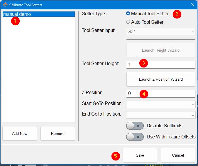
- To create a new manual tool setter, press 'Add New'. All tool setters must have a unique name. After naming the tool setter, select it from the list, and the settings for that tool setter will be shown on the right-hand side.
- Select the setter type to be manual.
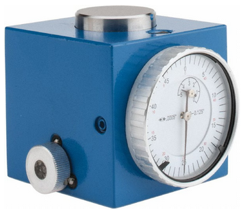
- Measure the height of your setter, and enter it into the Tool Setter Height field.
- The Z position for the tool setter should be the machine coordinate for the surface the tool setter is sitting on.
- If the tool setter is permanently mounted and the Z position does not change, the Z position wizard can be used to determine this number. Once it is set correctly, it will not need to be changed. Set a GoTo position so that the spindle will always go to the setter before touching off. If the setter is mounted outside of soft limits, toggle 'Disable Softlimits'.
- If the tool setter is used in random locations, or the table height changes, then set the Z position to 0.0 and leave the GoTo positions blank.
- Click Save
Using a randomly placed tool setter

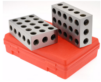
- Remove all tools from the spindle, and touch off the manual setter or gauge blocks. If your spindle uses tool holders or collets, insert an empty holder into the spindle while setting the Z position.
- Click the Set Position button. This will use the position of the tip of your spindle and the height of your setter to set the Z position.
- Insert and measure each of the tools you need for this job.
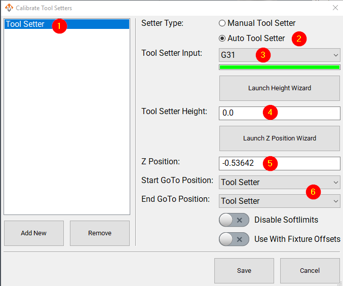
Creating an Auto Tool Setter
 |
|
- Add a new tool setter with an appropriate name
- Select the setter type to be auto.
- Select the probe input the setter is wired to. The bar below the input selector will turn green when the tool setter is triggered. You, or a helper, can manually trigger the setter to confirm that you have the correct input.
- If the tool setter height is known, its height should be entered. If the tool setter height is not known, launch the height wizard and follow the instructions for measuring. This will require the tool setter to be wired to the control.
- The Z position for the tool setter should be the machine coordinate for the surface the tool setter is sitting on. The Z position wizard can be used to determine this number if it is not known. If the tool setter is randomly placed, not fixed, then this value will be set to 0.0 here, and will be set each time before you begin measuring tools. See the instructions above: Using a randomly placed tool setter
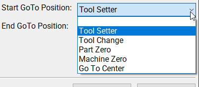
- Optionally, select goto positions to be associated with this tool setter.
- Selecting a position will cause the machine to go to that position before touching off with this setter. That works very well with a permanently mounted setter. If the position is outside of soft limits, turning on 'disable softlimits' will be needed to reach the setter.
- With a randomly placed setter, leave these fields blank. Either jog the spindle to the setter, or move the setter to the spindle. When you begin the process, there will be no automatic jogging.
Creating a Tool Setter Go-To Position
This is documented in Modifying GoTo Positions
Align Tool Edge to Center of Tool Setter
This feature will position the edge of the tool to the center of the tool setter. To begin using this feature set the parameter Tool Setter Align Tool Edge To Setter to Yes. Next configure the parameter "Tool Setter Align Tool Edge Offset" and choose between using "Tool Radius" or "Tool Setter Offset" as the source for the offset needed to align the tool edge to the center of the setter. Lastly choose which direction to offset when aligning the tool edge to the center.
Configure the following Parameters:
| Parameter Name | Value | Optional Values | Default Values |
| Tool Setter Align Tool Edge To Setter | Yes | No | |
| Tool Setter Align Tool Edge Offset | Tool Setter Offset | Tool Radius, Tool Setter Offset | Tool Radius |
| Tool Setter Align (X or Y) Axis To Setter | X Positive | X Positive, X Negative, Y Positive, Y Negative | X Positive |
Parameter "Tool Setter Align Tool Edge Offset" must be set to "Tool Setter Offset" before the Tool Setter Offset column will show up in the tool table.
View and Edit the tool table directly
In the upper left corner of the Tools tab is the Tool Table button
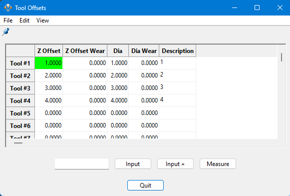
This table can be customized extensively to meet the needs of your system. Please see Tool Offset Table Customization
Start-Up Procedure

Warranty Information
MachMotion warranty policy is subject to change. Updated information is available at our website:
https://machmotion.com/warranty
The MachMotion Team
http://www.machmotion.com
14518 County Road 7240, Newburg, MO 65550
(573) 368-7399 • Fax (573) 341-2672