2000 Series Waterjet Operating Manual
Introduction
Overview
This manual gives an overview for the basic operation of the MachMotion Waterjet control. The screen is shown below, followed by a brief summary of the different features of the screen. The numbers shown in the screenshot refers to a brief description below the image.
Control Startup
To open the control software, double-click on the profile icon on the desktop.
Control Screen Overview
G-code Tab
- Toolpath
- Regen Toolpath: refresh the displayed toolpath
- View Top: top view of the part
- View ISO: side view of the part
- File
- Recent: load a recently loaded G-code program
- Load: load a G-code program from the computer
- Edit: edit the G-code program currently loaded into the control
- Close: close the G-code program that is currently loaded into the control
- Advanced
- Single Block: when active, the control will go line by line through the G-code program when the operator presses [Cycle Start]
- Block Delete: when active, the control will skip the lines in the G-code program indicated by their block level
- Part Counter: displays the number of parts that the machine has produced
- M1 OPT Stop: when active, the control will stop at any M1 command in the G-code program and wait for the operator to press [Cycle Start]
- Dry Run: when active, the control will ignore all mist or flood commands
- M-S-T Lock: when active, the control will ignore all M-codes, jet commands, and tool commands
- File Resume: allows the operator to select a line of G-code to start the program from and makes the control ready to run from that location
- Collapse: minimizes the advanced section to only show M1 OPT Stop and File Resume
- Status
- Status: displays the most recent message
- State: displays the current control state
- Cycle Time: displays how long the G-code program has been running
- Date: displays the current date and time of the control
- Axis Digital Readouts
- For each axis on the control, there is the following:
- A DRO displaying the current position
- A DRO displaying the distance left to travel
- A gauge displaying the current load on the axis
- Indication that the axis has not been homed if the axis letter is flashing
- MDI: opens or closes a window for G-code commands
- Viewing Part: toggles the axis position DROs between machine coordinates and the current fixture coordinates
- For each axis on the control, there is the following:
- Active Modals
- Active Offset: displays the current fixture offset
- Tool Display
- T: displays the current selected tool number
- Next Tool: displays the next tool to be used by the G-code program
- Diameter: displays the stored diameter of the current tool
- Length: displays the stored length of the current tool
- Feedrate Display
- F: displays the current commanded feedrate
- Feed OV: displays the current feedrate override percentage (0-300%)
- Rapid OV: displays the current rapid override percentage (0-100%)
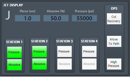
- Jet Display
- Pierce Delay: displays the current pierce delay while jets are turning on in seconds
- Abrasive Rate: shows the rate of abrasive output at a percentage of ability
- High Pressure: toggles if the jets operate in high pressure mode
- Cut Recovery: moves machine to the closest point on the path of the loaded G-code program and asks for confirmation to start cutting from there
- Station 1 - 4: toggles which jet stations will turn on when jets are on and which stations also use abrasive
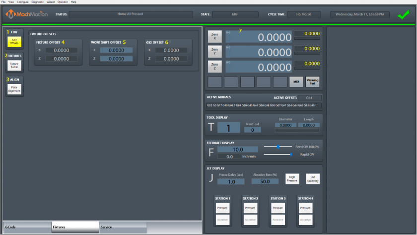
Fixtures Tab
- Edit
- Edit Offsets: edit the active fixture offsets
- Fixtures
- Fixture Table: view and edit the fixture table for all fixtures
- Align
- Plate Alignment: open plate alignment wizard to rotate machine for crooked plate material
- Fixture Offset
- Displays the current fixture offset for each axis
- Work Shift Offset
- Displays the current work shift offset for each axis and allows the operator to edit them
- G52 Offset
- Displays the current G52 offset for each axis
- Axis Digital Readouts
- For each axis on the control, there is the following:
- A DRO that displays the current position and allows to edit the current fixture offset
- A DRO displaying the distance left to travel
- A gauge displaying the current load on the axis
- A button to zero the current fixture offset to the current location
- For each axis on the control, there is the following:
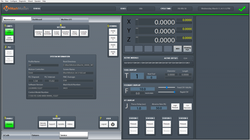
Service Tab
Maintenance Tab
- Limits
- Soft Limits: toggles software limits on or off
- Limit Override: toggles to allow for the machine to move off a limit switch
- PLC
- Reset Pocket: only used for tool changers
- PLC Sequence
- Enable
- Disable: toggles if the machine is enabled or disabled
- Settings
- Interface Config: opens the MachMotion parameters for editing
- Motion Controller: opens the configuration for the active motion controller
- Screen Config: opens the configuration to change the colors and password protect aspects of the screen
- Industrial Theme: applies standard colors to screen objects
- Toggle Menu: opens settings for top menu bar
- Compile Scripts: refreshes programming scripts
- Homing
- Home X: sends X axis to do its homing routine
- Home Y: sends Y axis to do its homing routine
- Home Z: sends Z axis to do its homing routine
- Home All: all axes do their homing routine in their configured order
- Support
- Remote Support: starts a remote support session with the MachMotion technical support team
- Support: opens the online MachMotion Support Library
- Updates: checks for updates to the MachMotion control software
- History: view the operator message history
- User
- Logout: logs out of the Windows username
- Power: turns off the computer
Dashboard Tab
The dashboard is used to make the control just the way you want it! For more information, read here.
Machine I/O Tab
This tab is used for diagnostics and shows all enabled machine signals.
Homing
To home the machine, begin by pressing the [Reset] button. Then navigate to the [Service/Maintenance] tab and press [Home All]. There is an optional parameter to prompt the user to home the machine on startup.
Programmed Movement
MDI
To command a movement using the MDI feature, press the [MDI] button.
G-code
The primary method of commanding motion is using G-code files. G-code files can be hand written, generated by a wizard, or generated from CAD files using a CAM program.
Toolpath Screen
The controls to manipulate the toolpath screen are as follows:
-
- Zoom – Right click with the mouse and move mouse up/down or using the scroll wheel on the mouse
- Rotate – Left click with the mouse and rotate the part by moving the mouse
- Pan – Press and hold [Ctrl] on the keyboard and left click with the mouse, then pan by moving the mouse (one-hand control option is to use left and right mouse click and move the mouse. No [Ctrl] press needed)
Cut Recovery
The control comes with a feature that allows the user to jog the machine to anywhere on the part and start running the G-code program from there. Operation of this feature is as follows:
- Jog the machine close to the position to start from. Using the toolpath on the screen may help the operator get close to the path.
- Press [Cut Recovery] in the Jet Display group. The operator will be asked to press [Cycle Start] to confirm the motion on to the path.
- The control will evaluate if the jets should be on at this point in the file, and then ask the operator to press [Cycle Start] to confirm running the file from this point.
Jet Control
G-code Jet Commands
The jet is controlled with with M-codes M3 (On) and M5 (Off). These commands can be done in G-code or through MDI. Pierce, abrasive and High Pressure timers can all be set manually or set while calling the M3. Values set with M3 will override values set manually. The command should look like this: M3 P H E
P is pierce delay, H is pressure delay and E is abrasive delay. Time will be set in seconds. Example: M3 P2 H3 will turn on the jet with a 2 second delay and pressure on for 3 seconds. E is not called in this example so it will default to the user settings instead of what is called in the G-Code.
Manual Jet Control
To control the jet separately from G-code, use the spindle controls on the operator panel. The buttons for [FWD] and [REV] will both turn the jet on, while the [STOP] button will turn the jet off.
Jet Run Settings
The control supports up to four jets. A jet must be enabled in the parameters by mapping the appropriate outputs to control the pressure on, high pressure, and abrasive.
When commanding the jets on, the selection of which jets turn on is done on the screen. Each station can be selected individually if it should turn on and if it should use abrasive. All stations that are on will operate in high-pressure mode or not together. All stations using abrasive will use abrasive at the same rate. All stations that turn on will use the same pressure, abrasive, and pierce delays.
Configuring Jet Parameters
The MachMotion parameters can be accessed on the [Service/Maintenance] tab by pressing the [Interface Config] button.
In the [Jet/General] section, are parameters for the number of jets and the delay times to use while turning the jets on. The control supports up to four jet stations that are controlled simultaneously. The selection of which jets turn on is done on the screen.
For each jet, outputs must be mapped for turning on their pressure, abrasive, and high pressure states in the [Jet/Output] section. If the abrasive is a servo motor feed system, then the servo motor needs to be enabled in the [Jet/Abrasive] section and the appropriate axis ID assigned to it. The axis ID is the axis number that the motor is mapped to in Mach config. The axis must be an OB axis (axes 6-11).
To allow for jet height control while the machine is cutting, an axis must be mapped to the Z override axis. This axis ID must be an OB axis (axes 6-11) and must not be the same as an abrasive motor. The control must be restarted for changes to this value to take effect.
Jet On and Off Sequence
All enabled jets will turn on or off the outputs at the same time.
Jets On Diagram (M3)

Jets Off Diagram (M5)

Delay Descriptions:
1. Jet Abrasive Line Delay (ms) “JetAbrasiveDelay”- Turns Jet and Abrasive on at the same time. Then applies the delay. Identical to “Jet Abrasive On Delay” and “Jet Pierce Delay”.
2. Jet Abrasive On Delay (sec) “JetAbrasiveOnDelay”- Turns Jet and Abrasive on at the same time. Then applies the delay. Identical to “Jet Abrasive Line Delay” and “Jet Pierce Delay”.
3. Jet Abrasive Off Delay (sec) “JetAbrasiveOffDelay”- Turns off Abrasive, applies delay, Turns off Jets. Identical to "Jet Abrasive Purge Line Delay"
4. Jet Abrasive Purge line Delay (ms) “JetAbrasivePurgeDelay”- Turns off Abrasive, applies delay, Turns off Jets. Identical to “Jet Abrasive Off Delay”.
5. Jet Pre-Off Delay (ms) “JetPreOffDelay”- Applies delay, then turns Jet off.
6. Jet Off Delay (ms) “JetOffDelay”- Turns Jet off, then applies delay.
7. Jet Pierce Delay (sec) ““JetPierceDelay”- Turns Jet on, then applies delay.
8. Jet Pressure Delay (ms) “JetPressureDelay”- Turns Jet on, then applies delay, then turns on Abrasive.
9. Jet High Pressure Delay (ms) “JetHighPressureDelay”- When “High Pressure Toggle” is high, it applies the delay, then turns on Jet and Abrasive. No yellow wait bar appears.
10. Jet Pump On Delay (ms) “JetPumpAutoOnDelay”- Turns on Pump, applies delay, flashes button until delay is over.
M-Codes
|
M3 |
Jets On, Optional values: P = Pierce Delay (sec) E = Abrasive Delay (sec) H = Pressure Delay (sec) K = Abrasive Rate (0-100%) S = Pressure (psi) overwrites #9000 |
| M5 | Jets Off |
| M170 | Jets Abrasive Master Enable On |
| M171 | Jets Abrasive Master Enable Off |
| M172 | Jets High Pressure On |
| M173 | Jets High Pressure Off |
| M174 |
Jet Pump On
S = Pressure (psi) overwrites #9000 |
| M175 | Jet Pump Off |
G-Code Parameters
|
1910 |
Wiggle Piercing Circles During Pierce Delay (1 = On, 0 = Off) |
| 1911 | Wiggle Piercing Number of Loops |
| 1912 | Wiggle Piercing Diameter |
| 1913 | Wiggle Piercing Feedrate |
Pound Variables
|
9000 |
Commanded Jet Pressure (psi) |
Intensifier pump
You can set values between 1 and 10 seconds for turning the intensifier on and off. In [Configure | Control | Spindle tab] use the Accel Time for turning it on, and the Decel Time for turning it off.
Appendix
Warranty Information
MachMotion warranty policy is subject to change. Updated information is available at our website:
https://machmotion.com/warranty
The MachMotion Team
http://www.machmotion.com
14518 County Road 7240, Newburg, MO 65550
(573) 368-7399 • Fax (573) 341-2672


