2000 Series - Tool Setters and Offsets
Creating a Tool Setter
Open the Calibrate Tool Setters window. Found on the Tools tab.

Creating a Manual Tool Setter
|
|
|
|

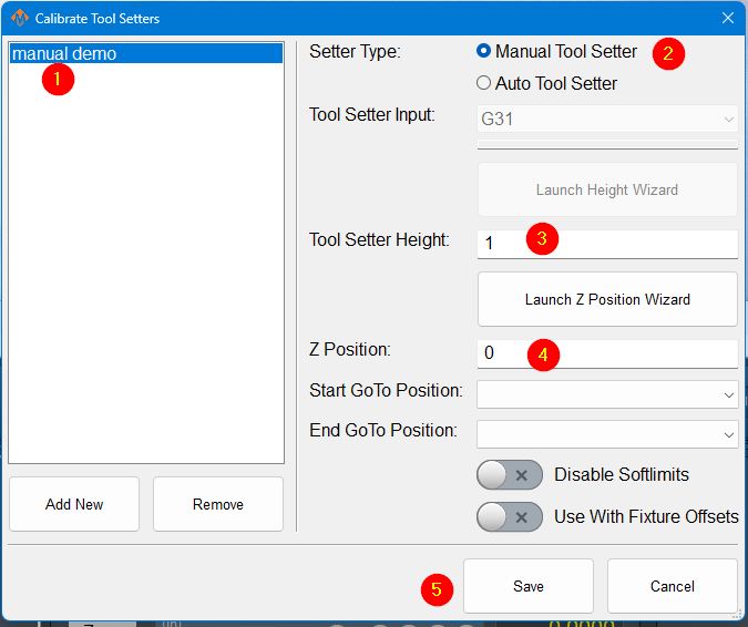
- To create a new manual tool setter, press 'Add New'. All tool setters must have a unique name. After naming the tool setter, select it from the list, and the settings for that tool setter will be shown on the right-hand side.
- Select the setter type to be manual.
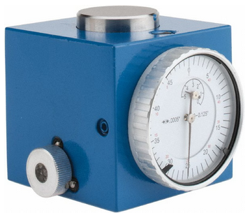
- Measure the height of your setter, and enter it into the Tool Setter Height field.
- The Z position for the tool setter should be the machine coordinate for the surface the tool setter is sitting on.
- If the tool setter is permanently mounted and the Z position does not change, the Z position wizard can be used to determine this number. Once it is set correctly, it will not need to be changed. Set a GoTo position so that the spindle will always go to the setter before touching off. If the setter is mounted outside of soft limits, toggle 'Disable Softlimits'.
- If the tool setter is used in random locations, or the table height changes, then set the Z position to 0.0 and leave the GoTo positions blank.
- Click Save
Using a randomly placed tool setter

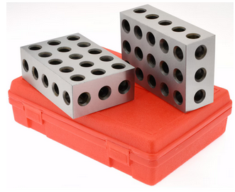
- Remove all tools from the spindle, and touch off the manual setter or gauge blocks. If your spindle uses tool holders or collets, insert an empty holder into the spindle while setting the Z position.
- Click the Set Position button. This will use the position of the tip of your spindle and the height of your setter to set the Z position.
- Insert and measure each of the tools you need for this job.
Creating an Auto Tool Setter
 |
|
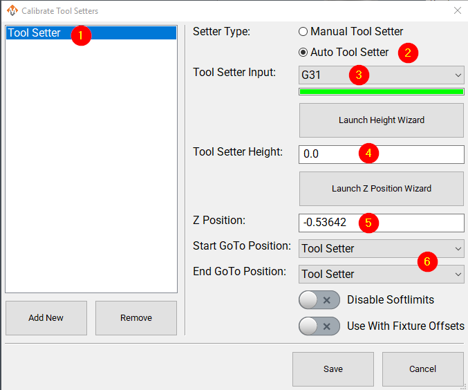
- Add a new tool setter with an appropriate name
- Select the setter type to be auto.
- Select the probe input the setter is wired to. The bar below the input selector will turn green when the tool setter is triggered. You, or a helper, can manually trigger the setter to confirm that you have the correct input.
- If the tool setter height is known, its height should be entered. If the tool setter height is not known, launch the height wizard and follow the instructions for measuring. This will require the tool setter to be wired to the control.
- The Z position for the tool setter should be the machine coordinate for the surface the tool setter is sitting on. The Z position wizard can be used to determine this number if it is not known. If the tool setter is randomly placed, not fixed, then this value will be set to 0.0 here, and will be set each time before you begin measuring tools. See the instructions above: Using a randomly placed tool setter
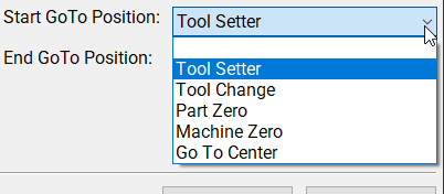
- Optionally, select goto positions to be associated with this tool setter.
- Selecting a position will cause the machine to go to that position before touching off with this setter. That works very well with a permanently mounted setter. If the position is outside of soft limits, turning on 'disable softlimits' will be needed to reach the setter.
- With a randomly placed setter, leave these fields blank. Either jog the spindle to the setter, or move the setter to the spindle. When you begin the process, there will be no automatic jogging.
Creating a Tool Setter Go-To Position
This is documented in Modifying GoTo Positions
Align Tool Edge to Center of Tool Setter
This feature will position the edge of the tool to the center of the tool setter. To begin using this feature set the parameter Tool Setter Align Tool Edge To Setter to Yes. Next configure the parameter "Tool Setter Align Tool Edge Offset" and choose between using "Tool Radius" or "Tool Setter Offset" as the source for the offset needed to align the tool edge to the center of the setter. Lastly choose which direction to offset when aligning the tool edge to the center.
Configure the following Parameters:
| Parameter Name | Value | Optional Values | Default Values |
| Tool Setter Align Tool Edge To Setter | Yes | No | |
| Tool Setter Align Tool Edge Offset | Tool Setter Offset | Tool Radius, Tool Setter Offset | Tool Radius |
| Tool Setter Align (X or Y) Axis To Setter | X Positive | X Positive, X Negative, Y Positive, Y Negative | X Positive |
Parameter "Tool Setter Align Tool Edge Offset" must be set to "Tool Setter Offset" before the Tool Setter Offset column will show up in the tool table.
View and Edit the tool table directly
In the upper left corner of the Tools tab is the Tool Table button
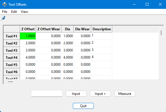
This table can be customized extensively to meet the needs of your system. Please see Tool Offset Table Customization