2000 Series General Installation Manual
![]()
This installation of a MachMotion control upgrade is the same process no matter what machine type, make or model. Please use the following manual as your guide to locate and mark the old wiring, remove the original system and install the new MachMotion complete system. If you need clarification, please contact MachMotion technical support to help you through the process.
MachMotion Technical Support: (573) 368-7399
Mount Back Panel
Remove old components
- Remove everything in the electrical enclosure besides the original transformer.
- Remove the old cables running to the motors.
Mount the new panel
- Mount the new electrical enclosure to the machine or if you just received a back panel it must be mounted similar to the image below.
(Back panel)

(MachMotion Full Cabinet - Apollo III Motion Controller)


Mount Control
See the 2000 Series Mounting Arm Manual to mount the arm and control.
Connect Control and Power
Connect Cables to the Control
- Remove round, rubber plug from the back of the control. Run conduit from the control to the back panel or electrical enclosure
.
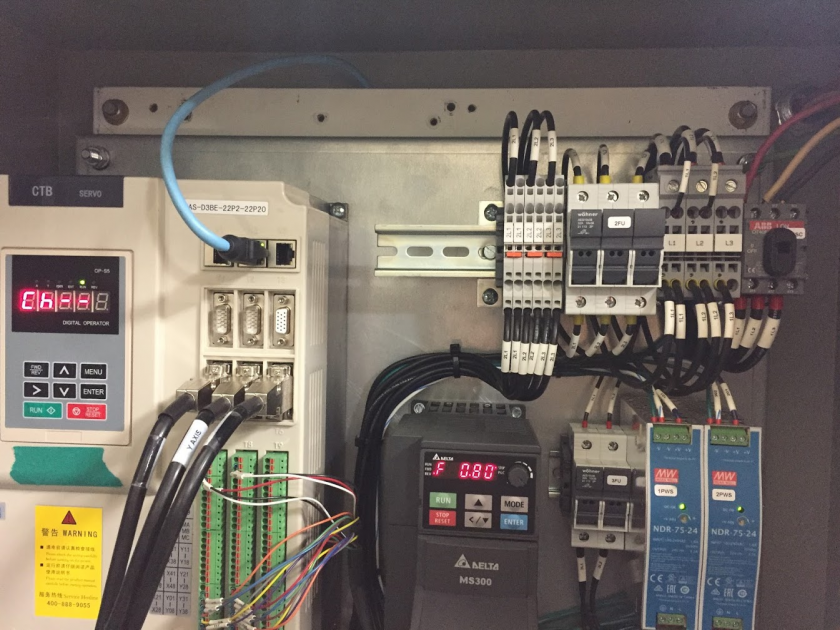
- Connect ethernet cables, power connector cable, and E-stop cables into the control as shown below. (If you have a Apollo III Motion Controller you will not need the EtherCAT blue cable)


Connect Cables to the Back Panel
- If using a RapidPath Motion Controller connect the light blue "EtherCAT" cable into N2 on the CTB servo drive.

(RapidPath Motion Controller) - Connect the green "Machine Network" cable into the VFD or the network switch.

(Yaskawa VFD)
(Apollo III)
(Machine Network Switch) - Connect the blue "Internet" cable to your local network if you do not plan to use the built in WiFi. Internet is not necessary to run the control. However, assistance from our support team will be greatly limited without access to the internet.
- Connect the HMI control Power Connector cable to PC 24V, PC 0V and GND blocks.

- For the Yaskawa drive, connect four E-stop cables to the E-10, E-11, E-20 and E-21 blocks as shown below.


Note: If you have an additional external E-stop, wire it in series with the control E-stop. You will need to connect your external E-stop into the 24V block and the other side into the blank terminal block. Then connect the red wire from the control E-stop into the blank terminal block as well. Finally, put the black wire from the control E-stop into the terminal block labeled E-Stop.
Wire Incoming Power
- Wire incoming power to the back panel into the top of the door switch. Be sure you are bringing in the recommended voltage that is on the panel nameplate.

Mount Motors
Mount the motors to the machine using the motor mounting plates provided (some improvising may be needed due to different styles of machines). If possible, take a look at the gears and write down the number of teeth on the motor gear and the ball screw gear. If you write down the gear ratio specifications, ball screw pitch, etc. now, it will make calibration much faster later.

(MachMotion Motors)
(Yaskawa Motors)
Run Cables
Route Motor Cables
Run the motor cables (encoder and power) from the motors to the back panel or enclosure. If the machine was equipped with CNC components before the upgrade the cables can usually follow the path of the old motor cables.
Take care when running the cables to keep them away from pinch points and sharp edges. The cables are protected by robust insulation but repeated wear and tear will cause damage and eventual failure. If the cables must run over a possible wear point, use some form of loom for additional protection. Keep in mind the motion of the machine and possible cable snag points while the machine is moving.
Connect Cables to Servo Drives
There are several different variations for connecting the motor cables to the servo drives. Please review the schematic that was sent to you by MachMotion.

Wire Spindle Motor to VFD
There are several different variations for connecting the motor cables to the VFD. Please review the schematic that was sent to you by MachMotion.

Wire Inputs and Outputs
Wire any inputs and outputs as shown in the diagrams below.
Output Commons
Please note, the output common comes pre-jumpered to the 120v circuit to the left of output wiring block as shown below. Verify the voltage of each output destination before wiring. If any of your outputs run on 24VDC, make sure the output common for that output is jumpered to 24V.

Wiring Lube System
Wiring Coolant System
For a contactor with 120VAC coil, wire it as shown.

Note: The contactor shown above is not included. Use the original contactor on your machine.
Coolant Pump Power
You can power up to a 0.5 hp 3 phase coolant motor. To run a 3 phase motor, the back panel will have to be powered with 3 phase. Run 3 wires from 2L1, 2L2, and 2L3 on the top of the back panel to the contacts on on your contactor.

Wiring Spindle Brake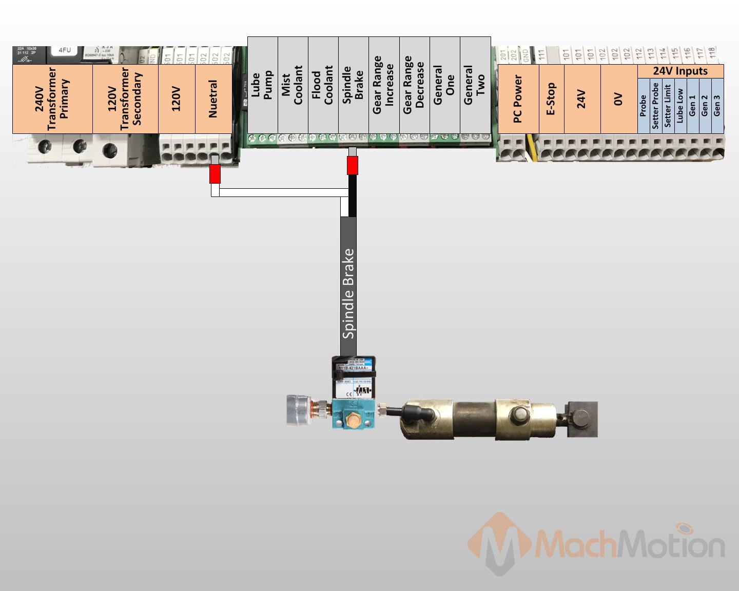
Wiring Tool Setter


Wiring Probe

Power System Up
Carefully inspect incoming power to make sure it is within range for your system.
We recommend utilizing a Multimeter to check incoming power.
- Turn the door switch on.
- Check the transformer is outputting the correct voltage as well.
- Run motion on the machine
- Lower the jog rate using the knob on the control

- Carefully jog each axis. Confirm that they are traveling in the right direction.
- If a motor is traveling in the wrong direction is can be easily reversed in the MachMotion software. Navigate to the top left of the screen and click Configure>Control and then click on the Motors. Select the problem motor and check the Reverse check box.
- Lower the jog rate using the knob on the control
- Test inputs and outputs
The best way to do this is use the buttons already setup for the intended function. For example, "Coolant" has a hard button on the control. You can also toggle signals manually by going to the Service tab, then Machine I/O. Double clicking on a signal will change its state. Double click again to change it back.

Configure Software
There are several options when configuring the MachMotion software. There is a Knee Mill Setup Wizard for all knee mill controls that are shipped out. For other machine types, review that particular machine type installation manual.
Knee Mill Setup Wizard

Softlimits
It is suggested to go through this part with the machine disabled and to use the handwheels to move the machine. It is possible to to move the machine with the jog functionality or pendant if the speed is turned down and caution is used.
Use extreme caution when jogging the machine as units have not been calculated and limits are not active.
The softlimits wizard will go through the three axes in order (X, Y, Z) and ask you to move the machine first to maximum travel and then to minimum travel. The positions should be within machine physical limits and within any limit switches on the machine, but should encompass most of the usable machine.

For each position, you will either need to select Set Softlimit or Skip in order to proceed. As you move through the wizard, the image will change to help you visualize the correct positions. When you set the maximum softlimits for each machine, the control will set your Home position to the same place, unless the machine has previously been homed.
For reference, while facing the machine, X maximum travel is with the table all the way to the left and the spindle nose all the way to the right of the table. Y maximum travel is with the table as close to the operator as it can go and the spindle nose near the far edge of the table.
After exiting the wizard, limits will be activated. It is now possible to enable the machine and jog the axes into their limits. When the limit is reached, the machine will cease moving in that direction. It is a good idea to turn down the jog rate and test the limits at this point.
Use extreme caution while testing limits in the event that an axis was accidentally skipped or set at an incorrect position.
Units
To set the units for each axis, the pitch of the ballscrew, the number of teeth on the ballscrew pulley, and the number of teeth on the motor pulley must be known. An advanced option is available for other systems of motion or if the data is not known.
The wizard will go through each axis individually in order (X, Y, Z). For each axis, you must enter the three pieces of data. Every time you change the data, the new units will be calculated and applied to the axis. To verify the units, a 1" dial indicator can be used. The wizard supplies options to move the axis back and forth distances up to an inch. Otherwise, verification can be done by manually jogging or commanding MDI motion.

Backlash
Some machines will not care about backlash on their axes. In that case, this step may be skipped. Backlash compensation will not completely compensate for all mechanical deficiencies.
Be sure to start this wizard with each axis near the middle of travel. The machine needs minimum of 1" of travel in all directions for this wizard to succeed.
The wizard supplies buttons for moving the machine positive and negative 1 inch, input for the amount of error, and an indication of direction of error.

For each axis, move the axis negative and then attach a dial indicator and zero it. Then move the axis positive once. Input the error from the indicator and select the direction of error. Then select Calculate & Apply. Verify the backlash by repeating the process until the machine is consistent.
Spindle Calibration
The spindle calibration wizard requires you to read the specifications from the spindle and insert them into the wizard. The information needed is the maximum RPM for low gear, the maximum RPM for high gear, and the amps for full load. These should be input and then Save selected.
The spindle can be tested by inputting a spindle speed on the screen and then pressing the Spindle FWD or Spindle REV buttons on the panel. If the spindle is turning the incorrect direction, the Reverse spindle direction check in the wizard can be toggled. Be sure to select Save.

If you need to calibrate your spindle with a tachometer, please see the Yaskawa V1000 / A1000 / GA500 VFD Installation Calibrate Spindle Speed section.
Other Machine Type Setup Procedure
Units Calibration
Before the machine is homed or any further setup is completed we must calculate our steps per/unit and calibrate the motors accordingly. MachMotion has a plugin to streamline this process.
- If you know the gear ratios, ball screw pitch, etc of your machine, use the Automatic Calibration shown here:
- Open Configure>Plugins>Machine Calibration
- Select Automatic Calibration
- For each axis, select the drive used for that axis, input the machine configuration, press Calculate, then Accept
- Close the calibration window
- Open Configure>Plugins>Machine Calibration
- If you do not know the gear ratios, ball screw pitch, etc of your machine, use the manual calibration shown here:
- Select Manual Calibration
- Select Commanded Distance
- Input 1 in the 'Distance to move axis' field
- If the machine is setup with metric units, enter 25.4 instead.
- For each axis, do the following:
- Setup a dial indicator for positive 1" machine travel
- Enable the machine
- Press the Move button
- Input the distance actually moved in the 'How far did the axis move' field
- If the machine is metric, be sure to enter distance traveled in millimeters
- Press Submit, then Accept
Homing and Soft Limits
With the motors calibrated, we can now home the machine and set up the software limits. Depending on the machine type you may be required to still utilize the existing physical limit switches. Refer to your specific machine type installation manual.
- Carefully jog X and Y to the negative extremes of travel and the Z axis all the way up as shown in the picture below.


Backlash Compensation
- Move an axis in one direction farther than the maximum possible backlash.
- Mount a dial indicator and zero it.
- Move the axis again in the same direction for a specific distance (it doesn’t matter how far).
- Move the axis backwards the same distance.
- Note how far the dial indicator was off from zero to see the axis’s backlash value.
- Input that data in the specific machine type motion controller
Spindle Gear Range Setup
To accurately setup the gear ranges on your machine, first set your variable pulley to the max range.

Take the max and min RPM for each gear range in input them in the gear range settings shown below. You can access this screen by going to Configure>Control>Spindle

Most machines will need to be reversed in one gear range or the other to compensate for the mechanical change. Check the Spindle RPM with a Tachometer. Adjust the MaxRPM value to compensate for any discrepancies in speed.
Lubrication Pump
Your kit is pre-configured with a relay to control the Lube Pump, as seen above. You can change the frequency and duration of which it runs in the MachMotion parameters.
Under the Service tab, click the "Interface Config" button.

Then search "Lube"

VFD Setup
Your Variable Frequency Drive will need to be calibrated for your motor. This can be done directly from the operating software. Under the Service tab, click the "Interface Config" button.
Now, search for your VFD. In the search bar (top bar outlined in red below), type in the model that came with your cabinet. It is either a "Yaskawa V1000". That will bring up the editable parameters (shown in the lower red box below). Simply highlight the value to change it. Many of these values may be able to remain the default ones.

You can find out what parameters need to be changed by looking at the info on your spindle motor name plate. Check and change any of the values that need it (Number of poles, wattage, amperage, etc.) to make sure your spindle runs at peak performance.

Additional Documentation
If you are just setting up your machine and getting used to the 2000 series control, check out these other manuals to learn how to use the Industrial Control and MachMotion Software.
For more info on the Control and Operator Panel, check out the "2000 Series HMI" (Human-Machine Interface) manual.
For information about MachMotion Software Operation please see "2000 Series Mill / Router Operating Manual"
Warranty Information
MachMotion warranty policy is subject to change. Updated information is available at our website:
https://machmotion.com/warranty
The MachMotion Team
http://www.machmotion.com
14518 County Road 7240, Newburg, MO 65550
(573) 368-7399 • Fax (573) 341-2672