MachPro Drill Bank Setup & Operation
![]()
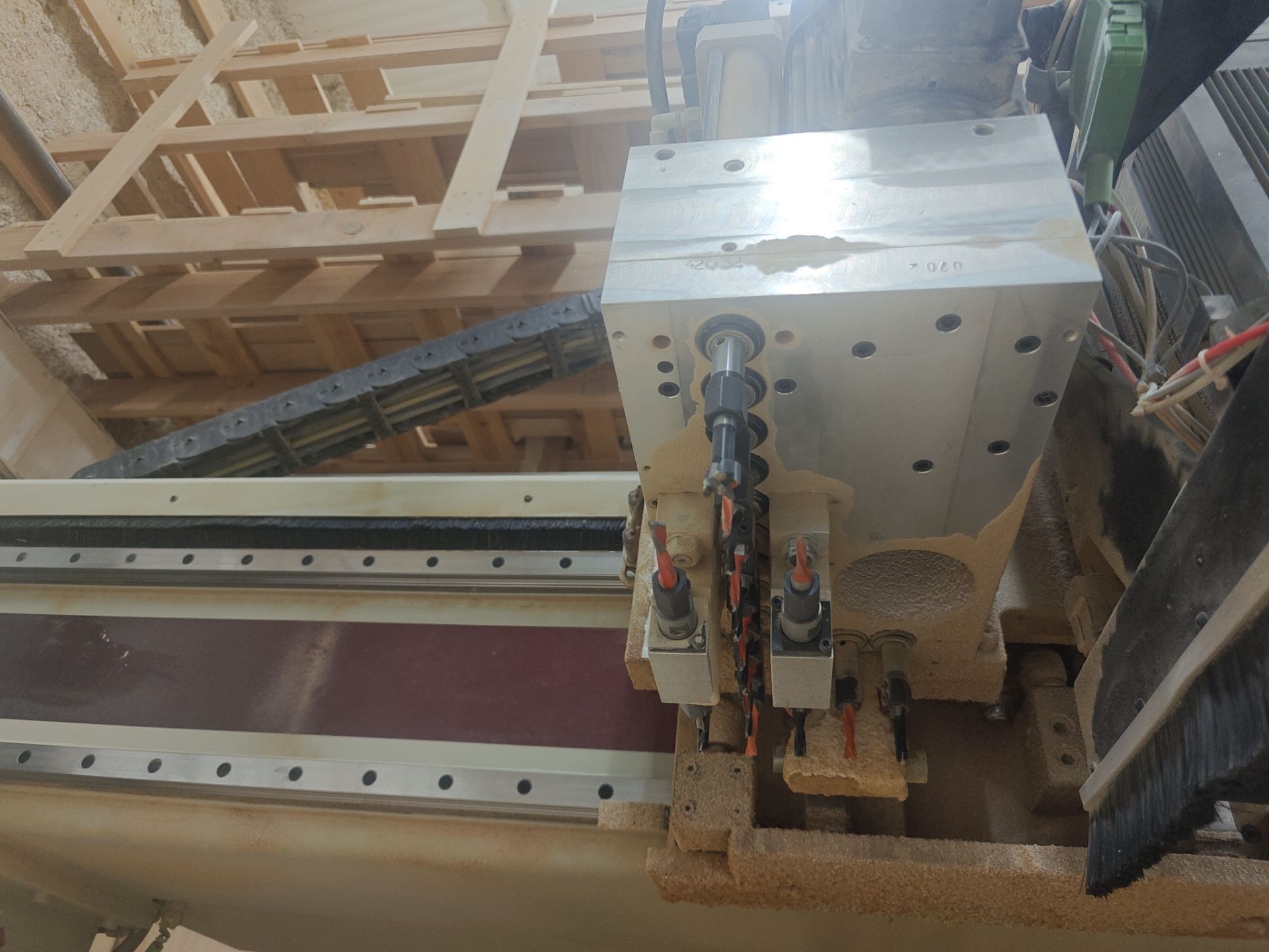
Example photo of a Drill Bank: (KOMO 20 Position Drill Bank. 14 Vertical, 6 Horizontal.)
Drill Bank Example Drawings (From above looking down):

In the above example; numbers 301-314 are Vertical Drills and numbers 315-317 are Horizontal Drill Units (2 drills per Horizontal Unit). This example does not isolate each Horizontal Drill, but instead is treating each Horizontal Unit as one tool. The offset to determine which of the 2 Drills will be used must be handled by the CAM software in this case. Often times each Drill within the Horizontal Unit will have a unique Drill number and can be offset within the CNC Controller with Tool Offsets.

In the above example; numbers 301-314 are Vertical Drills and numbers 315-320 are Horizontal Drill Units (2 drills per Horizontal Unit). This example does isolate each Horizontal Drill. The offset to determine which of the 2 Drills will be used may be handled by the CAM software or the CNC Controller. Often times each Drill within the Horizontal Unit will have a unique Drill number and can be offset within the CNC Controller with Tool Offsets.
Rotational Diagram (From above looking down):

Drill Bank 1 Setup
Map all overall Drill Bank features according to the requirements for the Drill Bank to begin and end a cycle
NOTE: Every Drill Bank is unique on how it functions. Basic understanding of the sequence is required for setup in the "Settings" blocks below! Not all parameters have functions that correlate to every Drill Bank. Some "Settings" will likely be left blank.

Then select "Settings".
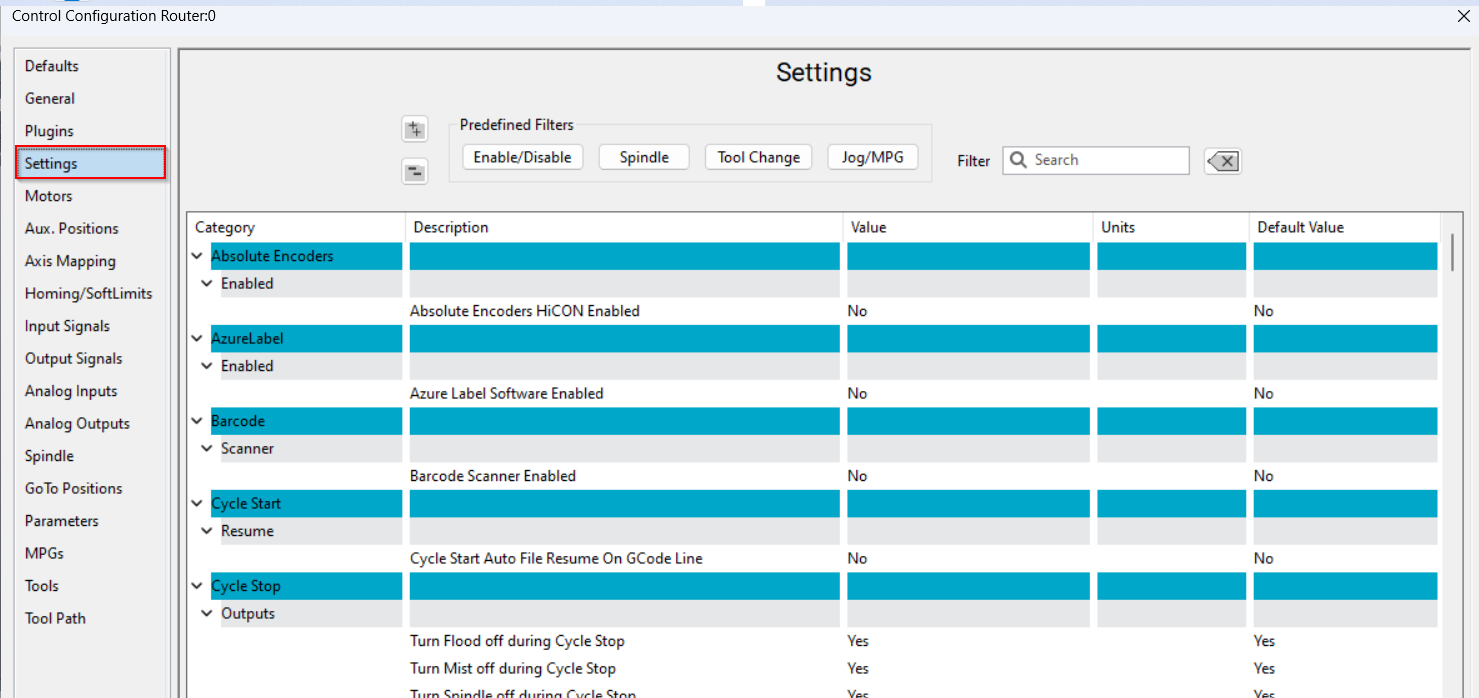
Search for "Drill Bank" and input the number of Drill Banks assemblies that your machine has. This value is looking for the the number of entire Drill Bank ASSEMBLIES your machine has. Not how many Drill Tools your Drill Bank has. The Drill Bank assembly is the entire unit housing all of the Drill Tools. Most Machines only have 1 Drill Bank Assembly.

1: "Engaged Input" is a confirmation signal to determine that the Drill Bank assembly did reach its desired engaged position. This is typically a magnetic switch on the air solenoid controlled by the "Engaged Output". This creates a more robust product if available but not mandatory for operation. If no input exists on the machine, the "Engaged Settle Time" delay can be used instead to wait for the Drill Bank to be in position before continuing with the Drill Cycle.
2: "Engaged Output" is the first action to occur when a Drill Cycle is called. This is typically an air cylinder to extend the Drill Bank assembly into a cutting position. Alternatively, it could be an air cylinder on the main Spindle that raises the Spindle up out of the way so that the Drill Bank can reach the material instead of the main Spindle.
3: "Engaged Settle Time" may be required if no "Engaged Input" is present. This will allow the Drill Bank assembly time to reach its proper position before beginning operation. This logic is true for all "Settle Time" style parameters.
4: "Drill Bank Motor On Output" is where you would map the output for the contactor for the Drill Motor that actually spins the drills.
5: "Parked Input" is the same logic but opposite direction of the "Engaged Input". "Engaged"=Prepared for cycle to start. "Parked"=Prepared for cycle to end. This is a confirmation signal to determine that the Drill Bank assembly did reach its desired parked position. This is typically a magnetic switch on the air solenoid controlled by the "Parked Output". This creates a more robust product if available but not mandatory for operation. If no input exists on the machine, the "Parked Settle Time" delay can be used instead to wait for the Drill Bank to be retracted before continuing with other operations.
6: "Parked Output" is the same logic but opposite direction of the "Engaged Output" Engaged=Move drill bank assembly to cut position. "Parked=Move drill bank assembly out of the way to resume standard operation. "Engaged" and "Parked" are typically opposing directions of the same cylinder. This is the last action to occur when a Drill Cycle is over. This is typically an air cylinder to retract the Drill Bank assembly into the idle position. Alternatively, it could be an air cylinder on the main Spindle that lowers the Spindle back down to resume operations outside of a Drill Call.
7: "Drill Bank 1 Range of Tool Numbers for Drill Bank" will have a range of numbers from the lowest Drill Tool number located within this Bank, to the highest. (Ex. If I have 2 Drill Banks with 16 Drills in each bank assembly, I would input "101-116" into the "Drill Bank 1 Range of Tool Numbers for Drill Bank" Parameter and "117-132" into the "Drill Bank 2 Range of Tool Numbers for Drill Bank" Parameter and so on. Up to 4 individual Drill Bank assemblies. Tool numbers for Drills should be in a range that will not overlap or interfere with standard Spindle Tooling numbers. Starting at 101 for Drill Bank Tool numbers is usually a safe bet for clarity and separation from standard Spindle Tooling, however, you have full control as to which numbers you choose as long you input proper data into this "Drill Bank 1 Range of Tool Numbers for Drill Bank" Parameter.
8: "Drill Bank 1 Associated Spindle" is where you would define which Spindle carries each Drill Bank assembly (Assuming you have more than 1 Spindle). (Ex. If my machine had 2 Spindles but only Spindle 2 had the Drill Bank assembly, I would input "2" into this section). Leave at the default value of 1 if you only have 1 Spindle on your machine.


Map individual Drill Solenoid outputs as needed.
1: "Drill Bank # All Drills Up Output" is where you would map the output signal for any existing solenoid that would retract all Drill Tools. Most machines do NOT have a solenoid that performs this function. It is entirely optional.
2: "Drill Bank # All Drills Up Settle Time" is where you would input a delay to allow for all Drill Tools to properly retract before continuing on with further operations. This value is ignored if your machine does not have a "Drill Bank # All Drills Up Output". It is also not needed if your Drill Tools retract extremely fast (most do).
3: "Drill Bank # Drill # Down Output" is where you would map the output signal for whichever given Drill Tool you want to fire to extend to a cut height. Tool #101 is the FIRST tool in the sequence so its solenoids output would be mapped to "Drill Bank 1 Drill 1 Down Output". Tool #102s output would be mapped to "Drill Bank 1 Drill 2 Down Output" and so on in order. Select the proper output signal to fire the solenoid associated to whichever tool number you are wanting to extend. (Ex. Lets say that I still have the same numbers in my "Drill Bank 1 Range of Tool Numbers for Drill Bank" Parameter as the example above "101-116" for my 16 tool drill bank. If I am wanting tool #101 (Drill 1) to extend when I call "M6 T101" (or "M91 T1" if Binary), I would map the output signal that extends tool #101 (Drill 1) to "Drill Bank 1 Drill 1 Down Output". If I wanted to fire tool #111, I would map the output signal that extends tool #111 to the "Drill Bank 1 Drill 11 Down Output". Every tool, 101-116, will be in order from "Drill Bank 1 Drill 1 Down Output" to "Drill Bank 1 Drill 24 Down Output".)
4: "Drill Bank # Drill # Up Outputs" operate as the opposite of the "Drill Bank # Drill # Down Outputs". The "Up" outputs will raise the Drill Bank Tools when the cycle is finished. Most machines only have single action solenoids for Drill Tools, so "Drill Bank # Drill # Up Outputs" are not required because merely turning off the "Drill Bank # Drill # Down Output" will raise the Drill back up without needing to fire an individual "Up" output.
Most Drill Banks do not have "Drill Bank # Drill # Up Outputs" or "Drill Bank # All Drills Up Outputs"

Drill Bank 2-4 Setup (Only applicable if your machine has MORE than 1 Drill Bank ASSEMBLY).
1-7: Will be the same logic as Drill Bank 1 setup listed above. Here you can distinguish different outputs that need to fire for a specific Drill Bank if your machine has more than 1.
8: "Drill Bank 2 Associated Spindle" is the same logic as the "Drill Bank 1 Associated Spindle" setting but specific to Drill bank assembly 2. (Ex. If your machine has 2 Spindles, and 2 Drill Bank assemblies, with a Drill Bank assembly on each Spindle head, you would enter "2" into the "Drill Bank 2 Associated Spindle" field to specify. However, if your machine had 2 Spindles and 2 Drill Bank assemblies, BOTH on Spindle 1, you would enter "1" into the "Drill Bank 2 Associated Spindle" field.
9: "Drill Bank 2 Range of Tool Numbers for Drill Bank" will be a continuation of the "Drill Bank 1 Range of Tool Numbers for Drill Bank" values. (Ex. If "Drill Bank 1 Range of Tool Numbers for Drill Bank" has the value "101-116", then my "Drill Bank 2 Range of Tool Numbers for Drill Bank" value should be "117-132" if I have 2 separate Drill Bank assemblies with the same number of Drill Tools).
Repeat these steps for all 4 Drill Bank assemblies if your machine has them.

Drill Bank Call Settings
"Drill Bank Tool Zero Action" dictates how the Drill Bank will behave when an "M91 T0" is called. With "Park Drill Bank and Restore Tool Number" selected, the Drill Bank will send all Drill Tools up, fully park the Drill Bank assembly, and restore the active Tool to the last known Tool number in the main Spindle. With "Send Drills Up" active, the Drill bank will only send up all Drill Tools currently down and will not park the Drill Bank assembly or return to the main Spindle Tool.

"Drill Bank Binary Tool Call Tool Activation" dictates which Drill Tool will the active Tool number when a Binary Drill Tool Call is made. The highest Drill Tool number or the lowest. This will affect which Tool Offset is applied.

"Drill Bank Motor Control Method" dictates when the motor that spins the Drill Tools turns on. Either automatically when a Drill Tool is called or wait for an "M3/M4" command for the motor to begin spinning.

"Drill Bank Tool Zero On Drill Bank Activation" dictates whether or not the main Spindle will park it's Tool in the Tool Changer before dropping the Drill Bank assembly and beginning a Drill Cycle. This is necessary for some machines that don't have enough clearance for the Drill Tools to reach the material if a Router Tool is currently in the main Spindle. Most machines have enough clearance and parking the main Spindle Tool would be a waste of time.

Update the Tool numbers in "C:\Mach\Profiles\Router\ToolTables\ToolInfo.Lua"
The value in the "Spindle (1)" being "99" shows why its commonly good practice to start Drill Bank tool numbers with "100+".
"Drill Bank (1)" "Start" and "Stop" need to reflect the value in 7: "Drill Bank 1 Range of Tool Numbers for Drill Bank".
"Drill Bank (2)" "Start" and "Stop" need to reflect the value in 7: "Drill Bank 2 Range of Tool Numbers for Drill Bank".
Default:

What it should be for this example:

For machines with more than 2 Drill Bank assemblies, copy the entire "Drill bank (1)" line of code and paste below the first 2 Drill Bank lines. The edit the values accordingly.

Go to Configure>Control>Tools
Change the "Max Tools" value to whatever your highest Tool number will be including the Drill Bank. The running example would need at least a value of "132" to function properly. This value can exceed the maximum Tool number on the machine. It just cannot be lower than the maximum Tool number used.

"Tool Offsets" page is where all tool specific data will be input. Below is the Default Tool Offset table:
The Default Tool Offset table is limited to the data shown and only 99 tools total.

Select the "Optional Fields" checkmark in the Tool Offset table

Vertical Drill Offsets
NOTE: The data below will be for VERTICAL Drill Tools only! HORIZONTAL Drill Tools will be described below this section.
1: "Length" will have the same meaning as standard tooling and can even be done on a tool setter if possible. You must determine how far down the Drill Bank assembly must travel before the tip of that drill bit reaches the same "Zero" as a measured Spindle Tool bit. This is describing how far the machine would need to offset the Z axis for the Drill Tool to be accounted for.
2: "Length Wear" has the same meaning as standard tooling. Not necessary for Drill bank Tooling.
3: "Diameter" is mostly unused in programing of Drill Tools. Unless a customer is intending to use Cutter Compensation on Drill Cycles, which would be extremely uncommon. The "Diameter" section should be left blank unless attempting to perform Cutter Compensation of the Drill Tools. The true "Diameter" will be accounted for in the "X Offsets" and "Y Offsets" as needed.
4: "Diameter Wear" has the same meaning as standard tooling and is useless for Drill Bank tooling if "Diameter" is also unused.
5: "Description" has no function and is strictly for note-keeping purposes. (Ex. "5mm CCW Drill")
6: "Pocket" should ALWAYS be 0 for Drill Bank Tooling as to not conflict with standard Spindle Tooling.
7: "X Offset" or "Offest" if spelled by a homeschooler, will be the distance from the center of your Spindle Tool bit to the center of the Drill Bank Tool bit you are setting up along the X Axis. This can be gathered by Zeroing the X and Y Axes, drilling a hole into material with the Spindle Tool bit, and then jogging over until you are lined up with the hole with the Drill Bank Tool you are trying to set up. Both X and Y Offsets can be achieved with the same hole alignment move. Input whatever distance is in your DRO into the "X Offset" field. Add or Subtract from this value as needed to dial in the perfect alignment with the Spindle hole. Tool Offsets for Drill Tools are dictated by how the CAM software handles Drill Cycle calls. Some CAM softwares handle all of the positions for the Drill Tools. In which case, the "X Offset" value should be left at "0" to not double apply the offset. Some CAM softwares offset to 1 specific Drill Tool (usually the "Corner" Drill). In which case, the "X Offset" for the "Corner" Drill Tool will remain at "0" and all other Drill Tools would need an offset to account for the distance from the center of the "Corner" Drill instead of the center of the Spindle Tool. And some CAM softwares don't offset for Drill Tools at all. Treating the positions for the Drill Cycles the same as the main Spindle. In which case, the "X Offset" would need the entire distance from the center of the Drill Tool to the center of the main Spindle Tool for all Drill Tools.
8: "X Offset Wear" has the same meaning as standard tooling. Not necessary for Drill Bank Tooling.
9: "Y Offset" or "Offest" if spelled by a homeschooler, will be the distance from the center of your Spindle Tool bit to the center of the Drill Bank Tool bit you are setting up along the Y Axis. This can be gathered by Zeroing the X and Y Axes, drilling a hole into material with the Spindle Tool bit, and then jogging over until you are lined up with the hole with the Drill Bank Tool you are trying to set up. Both X and Y Offsets can be achieved with the same hole alignment move. Input whatever distance is in your DRO into the "Y Offset" field. Add or Subtract from this value as needed to dial in the perfect alignment with the Spindle hole. Tool Offsets for Drill Tools are dictated by how the CAM software handles Drill Cycle calls. Some CAM softwares handle all of the positions for the Drill Tools. In which case, the "Y Offset" value should be left at "0" to not double apply the offset. Some CAM softwares offset to 1 specific Drill Tool (usually the "Corner" Drill). In which case, the "Y Offset" for the "Corner" Drill Tool will remain at "0" and all other Drill Tools would need an offset to account for the distance from the center of the "Corner" Drill instead of the center of the Spindle Tool. And some CAM softwares don't offset for Drill Tools at all. Treating the positions for the Drill Cycles the same as the main Spindle. In which case, the "Y Offset" would need the entire distance from the center of the Drill Tool to the center of the main Spindle Tool for all Drill Tools.
10: "Y Offset Wear" has the same meaning as standard tooling. Not necessary for Drill Bank Tooling.
Often Fanuc will use separate fixture offsets for the Drill Bank positioning. (Ex. G54, G55)
32mm is a very common spacing distance between Drill Tools! You can often Add or Subtract 32mm in the appropriate direction to the remaining Drill Tools "X Offsets" and "Y Offsets" after getting just one Drill Tool's position!

Horizontal Drill Offsets
1: "Length" is NOT the same for horizontal Drills as for vertical Drills! "Length" is still the VERTICAL distance to the top of the material. NOT the actual length of the horizontal Drill Tool! "Length" for horizontal Drills can be gathered by touching off on top of a material with the Spindle Tool bit, Zeroing the Z Axis at that position, performing a Tool Change to whichever horizontal Drill Tool you desire, then touching off the horizontal Drill to the top of the material, and inputting whatever the DRO shows for the Z Axis, Minus HALF of the horizontal Drill Tool's Diameter! Input this value into the "Length" field.
2: "Length Wear" has the same meaning as standard tooling. Not necessary for Drill Bank Tooling.
3: "Diameter" is mostly non-functional but more for documentation. Unless a customer is using Cutter Comp on Drill Cycles, which I don't believe to be something that we have encountered yet, the "Diameter" section can be blank with no issue.
4: "Diameter Wear" has the same meaning as standard tooling and is useless for Drill Bank Tooling if "Diameter" is also unused.
5: "Description" has no function and is strictly for note-keeping purposes. (Ex. "5mm CCW Drill")
6: "Pocket" should ALWAYS be 0 for Drill Bank Tooling as to not conflict with standard Spindle Tooling.
7: "X Offset" or "Offest" if spelled by a homeschooler, will be the distance from the center of your Spindle Tool bit to the tip of the Drill Bank Tool bit you are setting up along the X Axis. A Horizontal Drill bit that is pointed in line with the X Axis will have a "X Offset" as what would really be the "Tool Length" on a vertical tool. This value can be gathered by jogging alongside a 3D material with the Spindle Tool bit along the X Axis, Zeroing the X Axis, commanding a tool change to whichever horizontal tool you are trying to set up, and then jogging over until you are touching the side of the 3D material with the tip of the Drill Bank Tool you are trying to set up. Add or Subtract (accordingly) half of the Diameter of the Spindle Tool bit. Input whatever distance is in your DRO into the "X Offset" field. Add or Subtract from this value as needed to dial in the perfect alignment with the 3D material. Tool Offsets for Drill Tools are dictated by how the CAM software handles Drill Cycle calls. Some CAM softwares handle all of the positions for the Drill Tools. In which case, the "X Offset" value should be left at "0" to not double apply the offset. Some CAM softwares offset to 1 specific Drill Tool (usually the "Corner" Drill). In which case, the "X Offset" for the "Corner" Drill Tool will remain at "0" and all other Drill Tools would need an offset to account for the distance from the center of the "Corner" Drill instead of the center of the Spindle Tool. And some CAM softwares don't offset for Drill Tools at all. Treating the positions for the Drill Cycles the same as the main Spindle. In which case, the "X Offset" would need the entire distance from the center of the Drill Tool to the center of the main Spindle Tool for all Drill Tools.
8: "X Offset Wear" has the same meaning as standard tooling. Not necessary for Drill Bank Tooling.
9: "Y Offset" or "Offest" if spelled by a homeschooler, will be the distance from the center of your Spindle Tool bit to the tip of the Drill Bank Tool bit you are setting up along the Y Axis. A Horizontal Drill bit that is pointed in line with the Y Axis will have a "Y Offset" as what would really be the "Tool Length" on a vertical tool. This value can be gathered by jogging alongside a 3D material with the Spindle Tool bit along the Y Axis, Zeroing the Y Axis, commanding a tool change to whichever horizontal tool you are trying to set up, and then jogging over until you are touching the side of the 3D material with the tip of the Drill Bank Tool you are trying to set up. Add or Subtract (accordingly) half of the Diameter of the Spindle Tool bit. Input whatever distance is in your DRO into the "Y Offset" field. Add or Subtract from this value as needed to dial in the perfect alignment with the 3D material. Tool Offsets for Drill Tools are dictated by how the CAM software handles Drill Cycle calls. Some CAM softwares handle all of the positions for the Drill Tools. In which case, the "Y Offset" value should be left at "0" to not double apply the offset. Some CAM softwares offset to 1 specific Drill Tool (usually the "Corner" Drill). In which case, the "Y Offset" for the "Corner" Drill Tool will remain at "0" and all other Drill Tools would need an offset to account for the distance from the center of the "Corner" Drill instead of the center of the Spindle Tool. And some CAM softwares don't offset for Drill Tools at all. Treating the positions for the Drill Cycles the same as the main Spindle. In which case, the "Y Offset" would need the entire distance from the center of the Drill Tool to the center of the main Spindle Tool for all Drill Tools.
10: "Y Offset Wear" has the same meaning as standard tooling. Not necessary for Drill Bank Tooling.

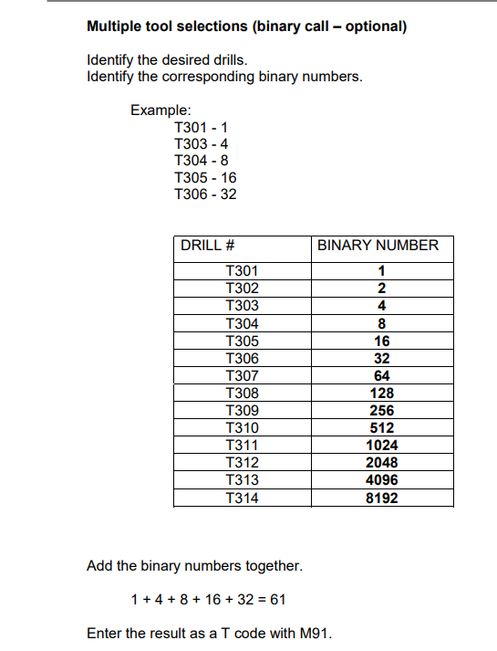
Binary Drill Calls
The Fanuc manual explaining this is attached as a PDF

Binary Drill Calls are preferred over standard "M6" Drill Calls. Binary Drill Calls drop/raise multiple Drill Tools at the same time. Opposed to standard "M6" Drill Calls which only drop/raise Drill Tools individually. (Ex. If you wanted Drills 1-4 to drop to bore 4 holes into the material, you could command a Binary Drill Call of "M91 T15" or a standard Tool Call of "M6 T101, then M6 T102, then M6 T103, and then M6 T104, each on their own GCode line"). The Binary example would drop all Drill Tools 1-4 immediately. The standard "M6" example would drop one at a time, applying appropriate settle times for each one before dropping the next. Standard "M6" calls are very tedious for Drill Cycles so Binary is preferred.
| http://www.mach-labs.com | MachLabs Documentation | support@machsupport.com |
The MachLabs Team
14518 County Road 7240, Newburg, MO 65550
support@machsupport.com