MachPro Lathe Setup Manual
![]()
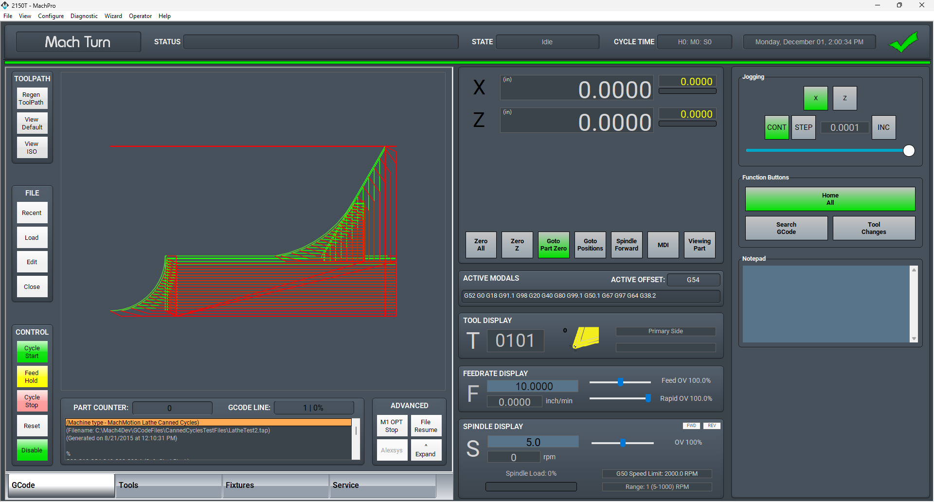
MachPro 26 CNC Software Roadmap
Introduction
Please refer to your motion controller's documentation to:
- Establish the network connection to the MachPro computer
- Connect and configure drives
- Connect and configure I/O
- Calibrate the axes
- Establish machine zero
- Configure soft limits
- Calibrate the Spindle
Some of these configuration steps need integration with the MachPro software. The M31 Motion Control Setup Manual includes the information you need for the M31. Compatible motion controllers should complete the MachPro Compatible Motion Controller Configuration Settings
Languages
| MachPro Version | 2026.5.13.1 and greater |
You may change the display language for the MachPro screen labels and buttons. This is an English-to-target-language word mapping feature, and you may freely switch between available languages. We will add more languages as there is a need. If you see something in your language that would be better translated with a different word or phrase, please submit a ticket so we can update it. support@mach-labs.com
If your CNC experience and training was primarily in English, it may be easier to configure MachPro while it is running in English. When the system is ready for daily operations, switch to an appropriate language for the operators. Be thoughtful in changing the display language. Use it as a tool to simplify your operations.
- From the main MachPro screen, pull down the Operator menu and click Select Language
- You need to restart MachPro after selecting a new language

Spindle Setup
See the M31 or Compatible Spindle Setup documentation
Spindle Calibration
This is for machines where the speeds and feeds are precise, and directly affect the finish and accuracy of the final part.
Spindle settings
These are the settings for the most commonly used Spindle features.
- Pull down Configure -> Control -> Settings tab
- Click the
 button to flatten the full settings tree, then expand the Spindle section


Gear shifter
Before configuring the gear shifter, you need to configure your gear ranges. Use this portion of the Spindle Calibration document for gear range configuration. Set MaxRPM values for each gear
The default settings will work for a machine with a manual gear shifter.
You may use M-codes to run the gear change cycle during a job. M40 - M45 change ranges from 0 to 5. M40 P# can also be used where # is the gear range to use
Load
Connect your encoder to an analog input and map the Spindle Load Meter Register to that input
Orient
MachPro uses M19 to run the orient sequence.
The two primary ways to use it are in Manual or Automatic mode
For Manual mode, the default configuration will work without any changes
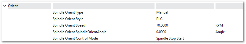
For Automatic mode configure:
- Spindle Orient Type Auto
- Spindle Orient Style Macro
- Spindle Orient Output
- Spindle Orient Input

You may change the other parameters according to what your system needs.
Sub Spindle
The minimum settings that need to be configured for the subspindle are:
- Sub Spindle Enabled
- Sub Spindle CW output
- Sub Spindle CCW output
- Sub Spindle Max RPM

Use M-codes to control the sub spindle
- M013 CW start
- M104 CCW start
- M105 stop
Spindle Warm Up
A spindle warm up cycle is important for all CNC machines, and especially important for machines that are not in a temperature controlled building.
- The cycle lubricates spindle bearings.
- It stabilizes spindle and machine temperature.
- It reduces thermal expansion changes during startup.
- It helps maintain machining accuracy.
- It reduces premature bearing wear.
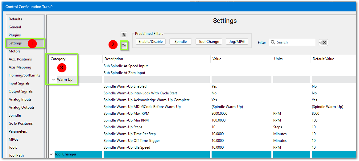
To configure a warm up cycle go to Configure ->Control->Settings tab.
- Collapse all of the settings with the
 button
 - Expand the Spindle section and scroll down to the Warm Up portion

Below are the default settings for the Spindle Warm Up.
| Parameter | Description |
| Spindle Warm Up Enabled | Warm Up Cycle On or Off |
| Spindle Warm Up Inter-Lock with Cycle Start | Yes or No |
| Spindle Warm UP Acknowledge Warm-Up Complete | The operator will need to acknowledge that the warm up cycle completed |
| Spindle Warm Up MDI GCode Before Warm UP | Provides an MDI field to enter GCode that will run before the Warm Up cycle begins |
| Spindle War Up Max RPM | Max (finishing) speed for the warm up cycle. This should be the Max RPM of the spindle |
| Spindle Warm Up Min RPM | Minimum (starting) speed for the warm up cycle (see note below). Set this to 1 |
| Spindle Warm Up Steps | How many steps will it take to get the spindle up to Warmed Up status - from Minimum to Maximum RPM |
| Spindle Warm Up Time Per Step | How long it will stay in each Spindle Warm Up Step |
| Spindle Warm Up Off Time Trigger in minutes |
How long do want the spindle to be off before the spindle will need to run the Warm Up cycle |
| Spindle Warm Up Idle Speed | Speed the spindle will idle at after the warm up is complete. Some spindles will not idle below 1500 RPM |
Example:
- Locate the manufacturer's warm up instructions. If you do not have those instructions, then set 2 minutes at each step, 3 steps, ending 1 step below max spindle RPM.
- For the Spindle Warm Up Min RPM, enter 1. It will start at the correct RPM and run each step and time as you specified.
- High speed spindle example: max warm up RPM of 18000, 3 steps, 2 minutes at each step (18000/3 = 6000)
- Standard Spindle example: Max warm up RPM of 2000, 3 steps, 2 minutes at each step (2000/3 = 667)
| Setting | High Speed Spindle | Standard Spindle |
| Max RPM | 18000 | 2000 |
| Min RPM | 1 | 1 |
| Steps | 3 | 3 |
| Time per step |
2 | 2 |
| system actions |
2 min at 6000 2 min at 12000 2 min at 18000 run at the spindle warm-up idle speed |
2 min at 667 2 min at 1333 2 min at 2000 run at the spindle warm-up idle speed |
Lube System Setup
![]()
If your system has an oiler edit the lube settings. Pull down Configure -> Control, and select the Settings Tab. Scroll down to the Lube System settings. Enable the lube system, and adjust the settings:
- choose an action trigger
- set the lube output
- set the time run time of the oiler
- set the time between cycles
Adjust the values according to your machine's needs. Note that lube pumps vary widely in their output. Start conservatively and increase the values to achieve proper lubrication.
In the example below:
- The lube system is enabled
- It runs on software timer settings
- But only when MachPro is enabled
- It does not run a cycle on startup
- The lube output is the MachPro software signal mapped to the pump output
- There is an option for a pressure sensor feedback input
- When the pump runs, it will run for 8 seconds
- It will remain off for 5 minutes between lube cycles
- This system is not using a PLC for the lube system

| http://www.mach-labs.com | MachLabs Documentation | support@mach-labs.com |
The MachLabs Team
14518 County Road 7240, Newburg, MO 65550
support@mach-labs.com
Next Steps
You may need to setup MachPro Advanced features, and you will need to use the MachPro Lathe Operating Manual to receive the full benefit of the new MachPro features.
| http://www.mach-labs.com | MachLabs Documentation | support@mach-labs.com |
The MachLabs Team
14518 County Road 7240, Newburg, MO 65550
support@mach-labs.com