MachPro Plasma Setup Manual
![]()
MachPro 26 CNC Software Roadmap

Configure Motion Controller
Please refer to your motion controller's documentation to:
- Establish the network connection to the MachPro computer
- Connect and configure drives
- Connect and configure I/O
- Calibrate the axes
- Establish machine zero
- Configure soft limits
MachPro needs to be integrated with your motion controller. If you have an M31 use the M31 Motion Control Setup Manual. If you have a compatible motion controller, then use MachPro Compatible Motion Controller Configuration Settings
Wire the ArcPro
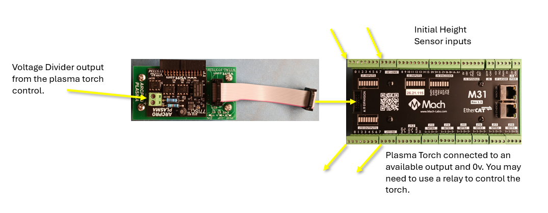
To the plasma control
The torch control will provide a voltage divider output and that is connected to the green Phoenix connector at the end of the ArcPro. The ArcPro provides Torch Height Control (THC) and makes the necessary height adjustments through the M31.
To the M31
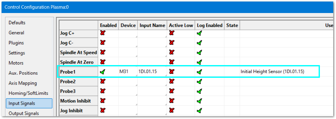
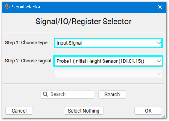
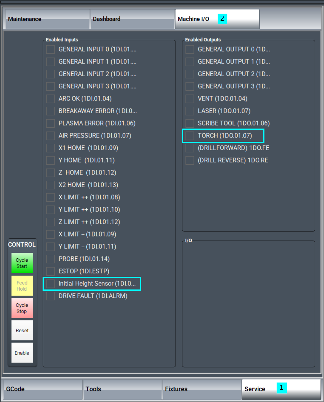
The Initial Height Sensor (IHS) needs an input wired to the M31 motion controller.
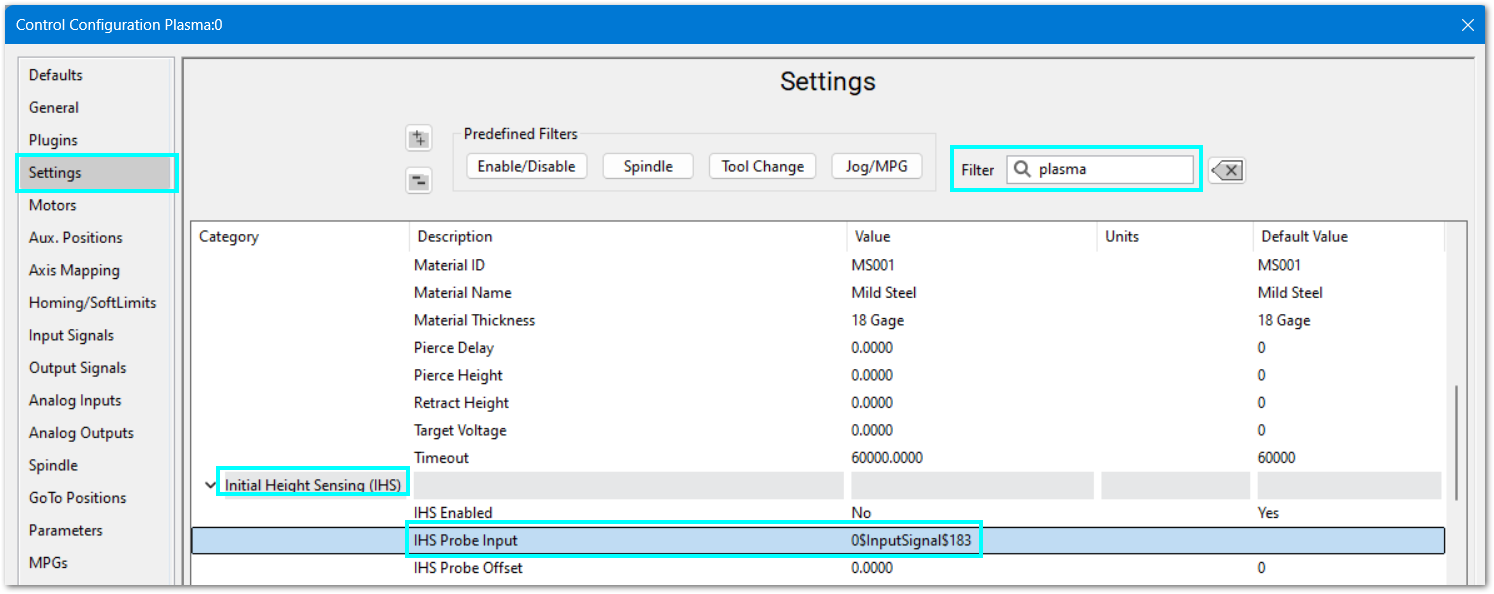
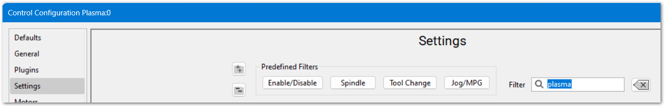
Pull down Configure -> Control -> and click the Settings tab.
|
|
|
|
|
|
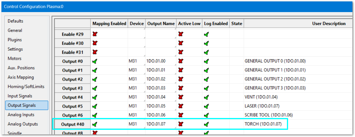
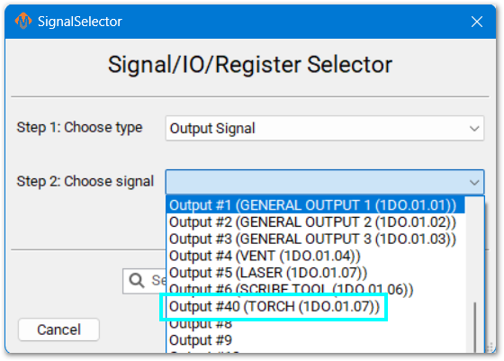
The M31 needs an output wired to the Plasma Torch control.
|
|
|
|
|
|
From the main MachPro screen, select the Service tab at the bottom, and then select the Machine I/O tab at the top.
This tab shows all enabled inputs and outputs. If you are not using any of these inputs or outputs, go back into the Configure screen and disable the unused I/O signals.
Default I/O Mappings
For both input and output signals: refer to the Mapping Signals section of the MachPro motion control configuration documentation for your motion controller. See the links in the table above. Manually trigger all inputs to verify they show correctly in the software, and manually trigger all outputs from the software to make sure that the device will operate properly.
A spreadsheet is attached (upper left corner of this window) with the default I/O signal mappings. You may print it for your use during the I/O configuration.
- Wiring reference and change notes
- Update descriptions in Input and Output signals configuration to match the way you have used the system previously
- Reference for future maintenance and updates to your system
Inputs
| SignalID | SignalName | Enabled | Device/Name | Active Low | State | Description |
| 1 | Input #0 | 1 | M31/1DI.01.00 | 0 | GENERAL INPUT 0 (1DI.01.00) | |
| 2 | Input #1 | 1 | M31/1DI.01.01 | 0 | GENERAL INPUT 1 (1DI.01.01) | |
| 3 | Input #2 | 1 | M31/1DI.01.02 | 0 | GENERAL INPUT 2 (1DI.01.02) | |
| 4 | Input #3 | 1 | M31/1DI.01.03 | 0 | GENERAL INPUT 3 (1DI.01.03) | |
| 5 | Input #4 | 1 | M31/1DI.01.04 | 0 | ARC OK (1DI.01.04) | |
| 6 | Input #5 | 1 | M31/1DI.01.05 | 0 | BREAKAWAY ERROR (1DI.01.05) | |
| 7 | Input #6 | 1 | M31/1DI.01.06 | 0 | PLASMA ERROR (1DI.01.06) | |
| 8 | Input #7 | 1 | M31/1DI.01.07 | 0 | AIR PRESSURE (1DI.01.07) | |
| 65 | Motor 0 Home | 1 | M31/1DI.01.09 | 0 | X1 HOME (1DI.01.09) | |
| 66 | Motor 1 Home | 1 | M31/1DI.01.11 | 0 | Y HOME (1DI.01.11) | |
| 67 | Motor 2 Home | 1 | M31/1DI.01.12 | 0 | Z HOME (1DI.01.12) | |
| 68 | Motor 3 Home | 1 | M31/1DI.01.13 | 0 | X2 HOME (1DI.01.13) | |
| 97 | Motor 0 ++ | 1 | M31/1DI.01.08 | 0 | X LIMIT ++ (1DI.01.08) | |
| 98 | Motor 1 ++ | 1 | M31/1DI.01.10 | 0 | Y LIMIT ++ (1DI.01.10) | |
| 99 | Motor 2 ++ | 1 | M31/1DI.01.12 | 0 | Z LIMIT ++ (1DI.01.12) | |
| 129 | Motor 0 -- | 1 | M31/1DI.01.09 | 0 | X LIMIT -- (1DI.01.09) | |
| 130 | Motor 1 -- | 1 | M31/1DI.01.11 | 0 | Y LIMIT -- (1DI.01.11) | |
| 161 | Probe | 1 | M31/1DI.01.14 | 0 | PROBE (1DI.01.14) | |
| 164 | E-Stop | 1 | M31/1DI.ESTP | 0 | ESTOP (1DI.ESTP) | |
| 183 | Probe1 | 1 | M31/1DI.01.15 | 0 | PROBE 2 (1DI.01.15) | |
| 251 | Input #100 | 1 | M31/1DI.ALRM | 0 | DRIVE FAULT (1DI.ALRM) |
Outputs
| SignalID | SignalName | Enabled | Device/Name | Active Low | State | Description |
| 1050 | Output #0 | 1 | M31/1DO.01.00 | 0 | GENERAL OUTPUT 0 (1DO.01.00) | |
| 1051 | Output #1 | 1 | M31/1DO.01.01 | 0 | GENERAL OUTPUT 1 (1DO.01.01) | |
| 1052 | Output #2 | 1 | M31/1DO.01.02 | 0 | GENERAL OUTPUT 2 (1DO.01.02) | |
| 1053 | Output #3 | 1 | M31/1DO.01.03 | 0 | GENERAL OUTPUT 3 (1DO.01.03) | |
| 1054 | Output #4 | 1 | M31/1DO.01.04 | 0 | VENT (1DO.01.04) | |
| 1055 | Output #5 | 1 | M31/1DO.01.05 | 0 | LASER (1DO.01.05) | |
| 1056 | Output #6 | 1 | M31/1DO.01.06 | 0 | SCRIBE TOOL (1DO.01.06) | |
| 1057 | Output #40 | 1 | M31/1DO.01.07 | 0 | TORCH (1DO.01.07) | |
| 1142 | Spindle Fwd | 1 | M31/1DO.FE | 0 | (DRILLFORWARD) 1DO.FE | |
| 1143 | Spindle Rev | 1 | M31/1DO.RE | 0 | (DRILL REVERSE) 1DO.RE |
Languages
| MachPro Version | 2026.5.13.1 and greater |
You may change the display language for the MachPro screen labels and buttons. This is an English-to-target-language word mapping feature, and you may freely switch between available languages. We will add more languages as there is a need. If you see something in your language that would be better translated with a different word or phrase, please submit a ticket so we can update it. support@mach-labs.com
If your CNC experience and training was primarily in English, it may be easier to configure MachPro while it is running in English. When the system is ready for daily operations, switch to an appropriate language for the operators. Be thoughtful in changing the display language. Use it as a tool to simplify your operations.
- From the main MachPro screen, pull down the Operator menu and click Select Language
- You need to restart MachPro after selecting a new language

Plasma Settings
Pull down Configure -> Control -> and click the Settings tab. You may want to open the settings and update them while working through the material below.
Enter Plasma into the filter at the top right of the screen. Within each section the settings are listed alphabetically. The most important values have default values that will work for many systems.
- Verify the default settings with your torch, voltage divider and torch height control documentation.
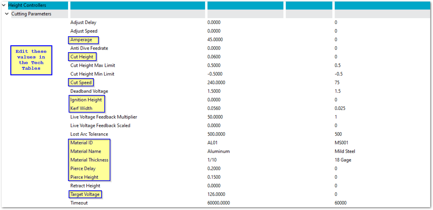
- When you select a material from the tech tables, the values for that material will be updated in the configuration settings. Change these values in the tech tables rather than in the Control Settings. See the Tech Tables section below.
- The Tech Table material values can also be set in the top of the G-Code file using these instructions: MachPro GCode WaterJet and Plasma Header Parameters
Voltage: divider, multiplier, live
Voltage management is a major factor in your plasma operation.
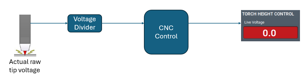
The Raw Tip Voltage is far too high to be read directly by your CNC control.
- The Live Voltage Feedback Scaled (Divided) is the ratio provided by your voltage divider. Example: for a 50:1 ratio, enter 50.
- The Live Voltage Feedback Multiplier will normally be the same as the voltage divider ratio.
The Live Voltage Feedback Scaled (Divided) takes the Tip Voltage and reduces it by a set ratio using a resistor network. It provides a fraction of the original voltage to the CNC control, and that is usable by the control. Sometimes that resistor network isn't totally accurate, and it provides a voltage to the CNC control that isn't exactly the rated ratio.
The CNC control takes the divided voltage, multiplies it by the the Live Voltage Feedback Multiplier and works with that number to manage the plasma cuts.
If your voltage system is providing good production quality without any fudge factors, then you may skip the following section. If you find that the reported voltage on the screen is a problem, then this will help.
In the examples below, the measured tip voltage is 75 volts.
- In the first example, the voltage divider works correctly, divides the 75 volts by 50, and sends 1.5 volts to the CNC control. The CNC controls multiplies that voltage by 50 and uses 75 volts as the live tip voltage for cut management.
- When the voltage divider is off, it will be off over the entire range of measured tip voltages by the same ratio.
- Measure the actual tip voltage with a multimeter while noting the live voltage reported by the CNC control.
- If the values match, no change is needed.
- If the values do not match, a simple math exercise will correct it.
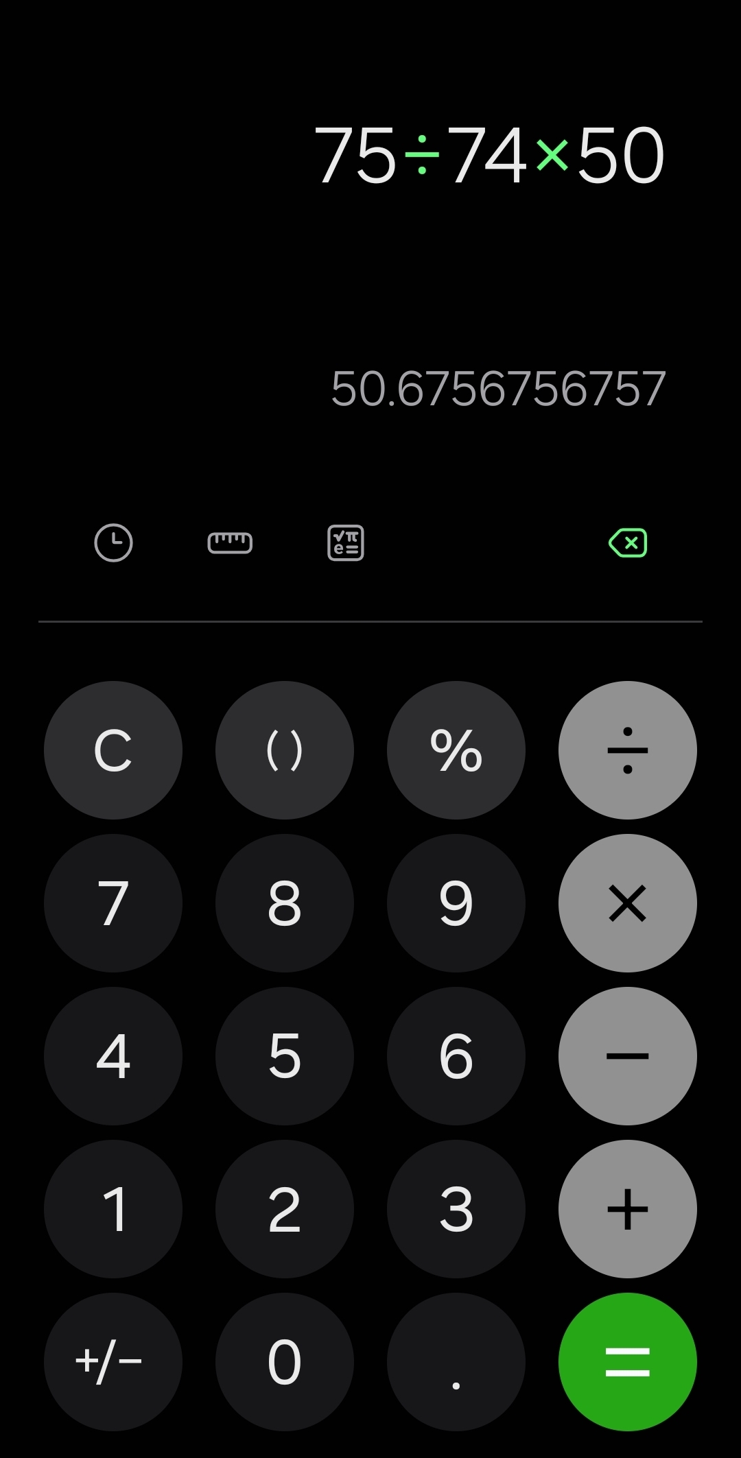
Measured Tip Voltage / Live Voltage from the screen X the current Live Voltage Feedback Multiplier = new Live Voltage Feedback Multiplier
|
In the second example, the voltage divider's resistors are off by a little. It divides the 75 volts and reports 1.48 volts to the CNC control. The control multiplies it by 50 and believes that the live tip voltage is only 74 volts.
Update the Live Voltage Feedback Multiplier to 50.6756 and the Live Voltage on the screen will match the measured tip voltage throughout the operating voltage range. |
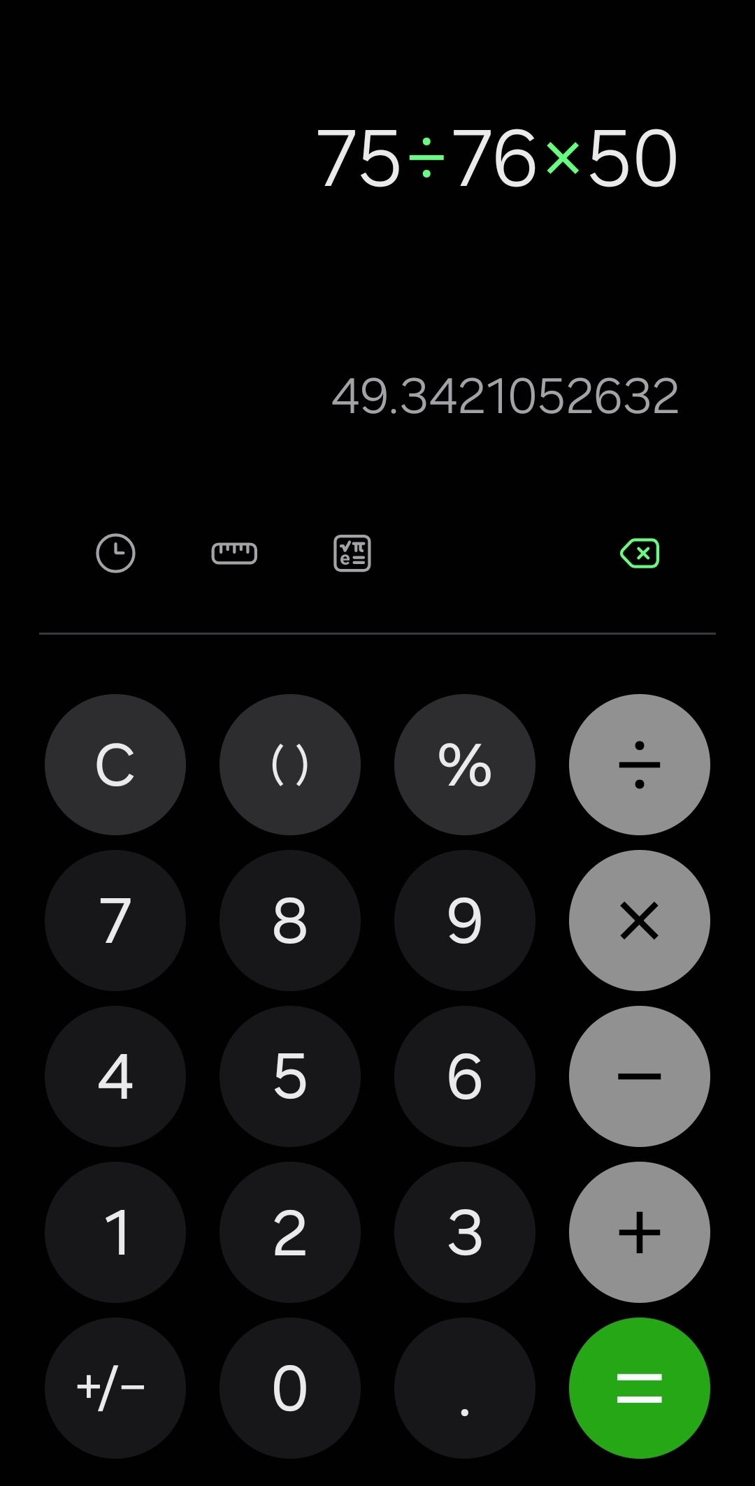
In the third example, the voltage divider's resistors are also off by a little. It divides the 75 volts and reports 1.52 volts to the CNC control. The control multiplies that by 50 and believes the live tip voltage is 76 volts.
Update the Live Voltage Feedback Multiplier to 49.3421 and the Live Voltage on the screen will match the measured tip voltage throughout the operating voltage range. |
Tech Tables
The Tech Tables are accessed through a button in the lower right corner of the Torch Height Control screen section.
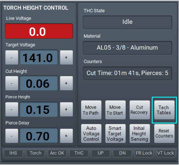
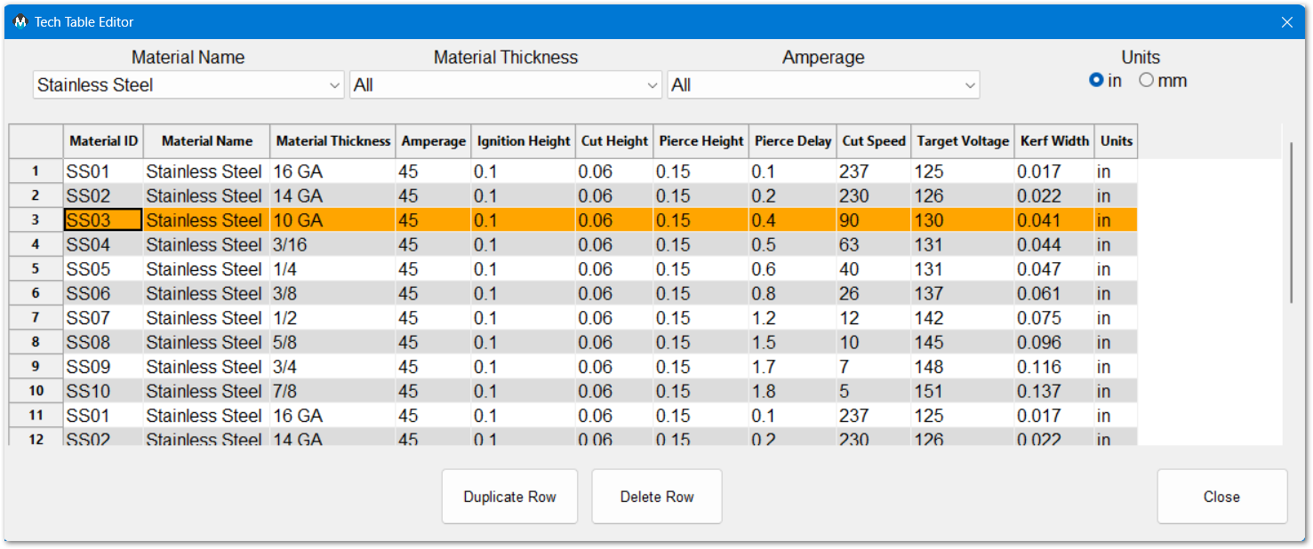
MachPro installs with a set of tech tables, and all of the values are editable. These values can also be set in each G-Code file using header parameters: MachPro GCode WaterJet and Plasma Header Parameters
Plasma cut sequence parameters
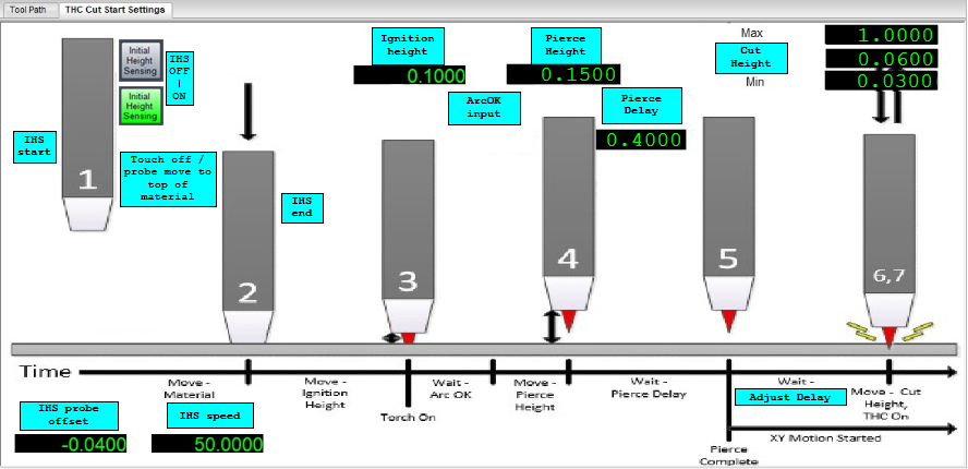
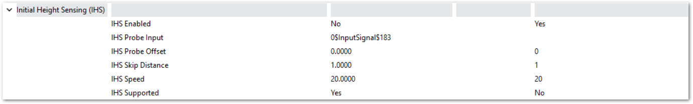
Initial Height Sensing (IHS)
The torch will touch-off / probe the work piece to determine the reference height, Z work height, Z part zero for all the following steps.
IHS can be temporarily enabled and disabled using the button on the lower right of the Torch Height Control screen section. When it is off, THC will begin without the IHS touch-off. In the Initial Height Sensing settings, it can be disabled completely with the IHS Enabled setting.
IHS Probe Offset is the distance between the physical touch-off and when the probe sensor triggers. Set this value so the IHS touch-off accurately sets the material work height. Manually jog the torch down to the work piece and note the Z coordinate. Then repeat using IHS touch-off. Enter any difference between your measured Z height and the IHS reported Z height as your IHS Probe Offset.
IHS Skip Distance is used on closely spaced parts where the initial height of the next cut is should be the same as the cut just completed, and a new probe is not needed. This saves cycle time on multiple cuts. Set this distance according to the part spacing.
Once the IHS sequence has probed the material, it sets the initial reference height (Z part zero) for the next steps.
Ignition Height is the distance above the work piece (part Z) to strike the arc. This is set in the Tech Tables.
Arc OK input signal comes from the torch control. The arc has been established and the pierce process begins. The torch will move to the Pierce Height and wait for the Pierce Delay to complete. Both of the Pierce values are set by the Tech Tables.
- Pierce Delay is the length of time required for the arc to pierce that type of material based on the other settings in the tech table. Once the Pierce Delay is complete, the torch will move to Cut Height and begin the G-Code XY movement.
Cut Height is set by the tech tables, and the THC will adjust the cut height to maintain the target voltage. The Cut Height Max Limit and Cut Height Min Limit establish the boundaries for THC adjustment.
Torch Height Control (THC) begins with the XY motion, and it can be delayed with the Adjust Delay to allow the arc to stabilize in the material and any initial voltage fluctuations to settle.
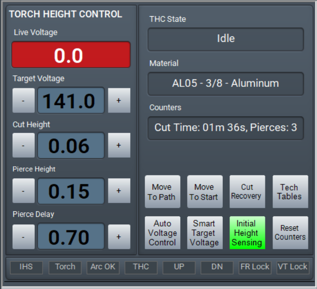
Torch Height Control (THC)
THC uses the tip voltage to maintain the torch height during the cut. MachPro supports two modes for THC:
- Auto Voltage Control uses a fixed voltage from the tech tables, or as set by the operator to maintain the torch height.
- Smart Target Voltage measures the voltage at the beginning of the cut and maintains that voltage level throughout the cut.
Within MachPro, the supported THC systems are:
- ArcPro Torch Height Control
- Plasma Roller Heads
- SoftHC (compatible THC controllers).
The ArcPro will use the incoming voltage signal from the voltage divider and adjust the torch height through the M31 motion controller.
The SoftHC uses the voltage signal from the voltage divider adjusts the torch height. It supports three modes: Manual, Digital, and Analog.
Other Settings
- Pull down Configure -> Control and select the Settings tab
- In the upper right corner of the window, enter plasma as the filter term
ArcPro
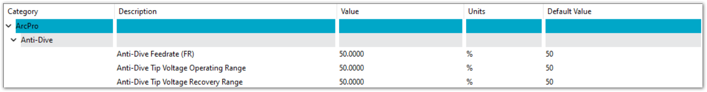
Anti-Dive Feed Rate (FR) %
Feedrate Anti-Dive prevents the THC from dropping the torch into a cut hole, diving into corners, or
diving at the end of a cut. When the XY cutting speed slows down, the plasma tip voltage increases, and
as a result, the response from the THC is to lower the torch. When the actual cutting feedrate drops
below the Anti-Dive Feedrate, FR Anti-Dive is engaged and the Z-Axis motion is disabled and stays locked
in position until XY feedrate increases above the FR antidive value.
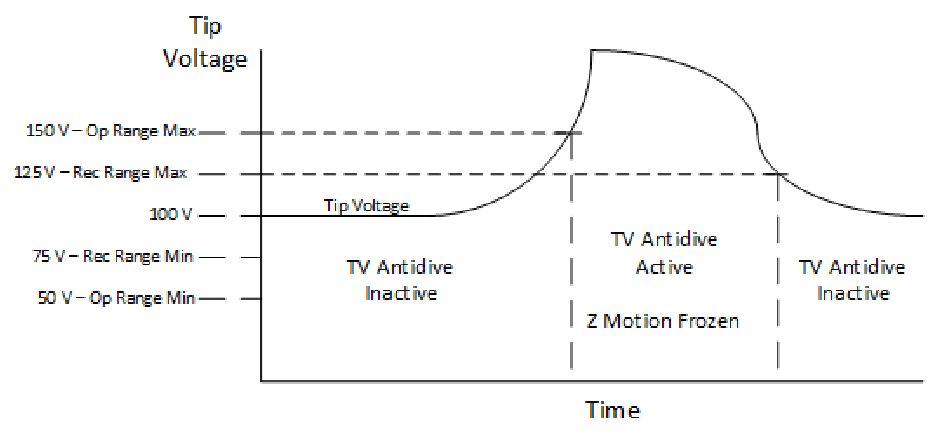
Anti-Dive Tip Voltage Operating Range %
This value determines a Tip voltage operating range above and below the current tip voltage every
50milli seconds. For example, a value of 50% for Tip Voltage Operating Range and a Tip Voltage of 100
would result in an effective THC range of 50-150V. Tip Voltage antidive will be activated (Z movement
frozen) if the Tip Voltage leaves this range during a 50 msec interval. This will prevent the torch head
from diving when encountering existing holes.
Anti-Dive Tip Voltage Antidive Recovery Range %
This value determines a Tip voltage recovery range above and below the current tip voltage every
50milli seconds. For example, a value of 25% for Tip Voltage Antidive Recovery Range and a current Tip
Voltage of 100 would result in an effective recovery range of 75-125V. Tip Voltage Antidive will be
deactivated (Z allowed to move) if the Tip Voltage enters this range in a 50 milli second interval. Note
that the Recovery Range % must always be lower than the Operating Range %.
General Height Settings
Adjust Delay
The amount of time in milliseconds after reaching Cut Height that Mach will wait before activating THC
(Torch Height Correction) on the motion controller. Please note that during this time span the GCode has
already begun and that the torch is moving in the XY plane.
Adjust Speed
This value represents the speed configured for the Z axis that the THC should move Z at when
performing THC corrections.
Anti-Dive Feed Rate (FR)
Feedrate Anti-Dive prevents the THC from dropping the torch into a cut hole, diving into corners, or
diving at the end of a cut. When the XY cutting speed slows down, the plasma tip voltage increases, and
as a result, the response from the THC is to lower the torch. When the actual cutting feedrate drops
below the Anti-Dive Feedrate, FR Anti-Dive is engaged and the Z-Axis motion is disabled and stays locked
in position until XY feedrate increases above the FR antidive value. This setting is separate from the ArcPro Anti-Dive Feed Rate.
Deadband Voltage
Represents a range around the Target Voltage in which the THC will not be activated. For example, a
Deadband Voltage of 5 and a Target Tip Voltage of 150 would mean that the THC will not update within
the range of 145-155.
Lost Arc Tolerance
This monitors the Arc OK signal and if that signal drops for more than the default 500 ms, it will stop the machine. The 500 ms value can be changed. It prevents abrupt system stops when the arc crosses previous cuts, oxidation, or voids. If the arc does not recover within the time value, then the system will stop. This works with anti-dive settings.
- Lost Arc Tolerance allows a short amount of time for the arc to recover before it stops XY motion.
- Anti-Dive prevents damaging Z axis dives into the material because of sudden arc voltage changes.
Retract Height
This value represents the distance that the Z axis will move up after turning off the torch with M5. This
value must be positive.
Timeout
The default is 6000 ms (6 seconds) that the control will wait for the Arc OK signal. If the signal does not arrive within this time, the system will fault out.
Initial Height Sensing (IHS)
Most of the IHS settings are covered above as part of the plasma cut sequence.
IHS Enabled
Turns the IHS probing function "on" in MachPro so the system executes a probe on every cut loop.
IHS Supported
The CNC controller, Z-axis, and sensory hardware possess the capability to safely find the top of the material surface before striking an arc.
Modifying GoTo Positions
Pre-defined GoTo positions are often used, and Modifying GoTo Positions explains how to configure and update them.
Machine Options
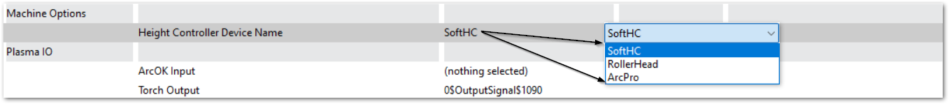
This is where you select the specific height controller you will be using. The settings specific to each type of height control are set in other labeled sections of these settings.
Shape Cutting
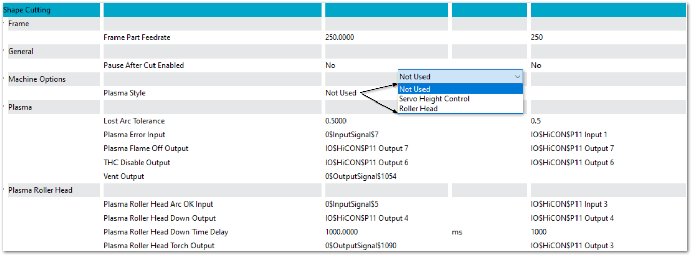
Frame Part Feedrate
You may configure a software function button on one of the dashboards to quickly use the unlit head to frame your part on the work piece. This will enable you to ensure that the head will not run off the edge while cutting the part. Set the feedrate for this function relatively fast, but not so fast that you cannot tell where the cut will be.
Pause After Cut Enabled
Yes or No.
Lost Arc Tolerance
This monitors the Arc OK signal and if that signal drops for more than the default 500 ms, it will stop the machine. The 500 ms value can be changed. It prevents abrupt system stops when the arc crosses previous cuts, oxidation, or voids. If the arc does not recover within the time value, then the system will stop. This works with anti-dive settings.
- Lost Arc Tolerance allows a short amount of time for the arc to recover before it stops XY motion.
- Anti-Dive prevents damaging Z axis dives into the material because of sudden arc voltage changes.
Plasma Roller Head Down Time Delay
The delay after the cut starts and before THC is turned on. It needs to be long enough to clear the initial cut location and stabilize in the cut.
SoftHC
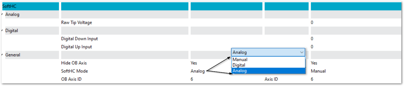
Raw Tip Voltage (input)
The input signal mapped to the input from your voltage divider.
Digital Down / Up Input
The inputs mapped to THC Up and THC Down.
Hide OB Axis
When the Z axis is is being controlled by THC, it is an Out of Band axis, and is not being directly controlled by MachPro. This provides a way to remove the OB axis from the DRO display in MachPro. It will continue to function properly during THC.
SoftHC Mode
Three modes are supported: Manual, Digital, and Analog.
OB Axis ID
The ID number of the Out of Band axis from the Axis Mapping tab.
Your MachPro plasma essential configuration is now complete. Some of these settings will also be used regularly while you are operating your system. This is the MachPro Plasma Operating Manual.
MachPro 26 CNC Software Roadmap
| http://www.mach-labs.com | MachLabs Documentation | support@mach-labs.com |
The MachLabs Team
14518 County Road 7240, Newburg, MO 65550
support@mach-labs.com