MachPro Advanced Configuration
![]()
MachPro 26 CNC Software Roadmap
MachPro is used for multiple machine types. Some of this documentation will be useful for all machine types, and some is only for certain machine types. Much of the software is already configured with values that that work well for most people. There are some portions of the software that will be most useful if you have additional details.
Modify the tool table
Open the Tool Table

Open the Tool Table Editor
-
In the tool table window, click Edit → Table Fields.

Add the X and Y Offset Fields
-
Click the Optional Field tab.
-
Find the field name XOffset, select it, and click Move Pri.
-
Do the same for YOffset.
-
Click OK to save.
-
You should now see X and Y offset columns in your tool table.
Set the Master Tool
-
Choose one tool to be your master tool.
Measure and Enter Offsets
- For each other tool, measure the distance from the master tool in both X and Y directions.
-
Enter those distances into the XOffset and YOffset fields for each tool.
Tool Spindle Rotation Options
Open the Tool Table
-
Click View → Tool Tables.
Open the Tool Table Editor
-
Click Edit → Table Fields.

Add a User Field for Spindle Options
-
Click the User Field tab.
-
Click Add.
-
Set up the new field exactly as shown in the example image.
-
Click OK when done.

View and Use the User Field
-
Click View → User Fields.
-
The new user field will now appear for each tool.

Set Rotation for Each Tool
-
For every tool, choose the correct spindle rotation option.
-
Example: For a probe tool, select No Rotation.
-
When you select a tool with “No Rotation,” you cannot turn on the spindle.
-
If you try, you will see an alarm message instead.


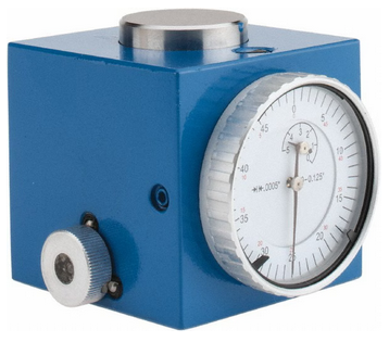
Tool Setters
![]()
Open the Calibrate Tool Setters window. Found on the Tools tab.

Creating a Manual Tool Setter
Mapping the input to a software signal
Pull down Configure -> Control and select the Input Signals tab.
Some signals are pre-configured when MachPro is installed.
Tool Setter Limit (Over Travel) maybe be mapped to Input #6
Tool Setter Input may be mapped to Probe1.
 |
 |
 |

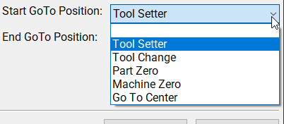
GoTo Position
- If the tool setter is permanently mounted, then define a GoTo Position so the spindle can safely move to the tool setter before touch-off.
- This ensures a consistent and safe approach, reducing the risk of collisions.
1. Add or Edit a tool setter
- In the Tool Setter tab, click Add New to create a new tool setter.
- Enter a unique name for the tool setter.
- Select the new tool setter from the list to display its settings on the right side.
2. Setter Type
- Under Setter Type, select Manual.
3. Tool Setter Height
- This is used with randomly placed tool setters to determine the Z fixture offset. If you have a fixed position tool setter, leave this value at 0.0
- Measure the physical height of the tool setter.
- Enter the measured value in the Tool Setter Height field.
4. Z Position
-
For a fixed positionsetter:
- Use the Z Position Wizard to determine the machine coordinate for the top surface of the setter.
- Once set correctly, this value should not be changed.
-
If the setter is mounted outside the soft limits, enable Disable Softlimits.
-
Once the Z position and height are calibrated, the system will automatically use these values for all tool length offset calculations.
Randomly placed tool setter
-
Set Initial Parameters
- Set the Z Position to 0.0.
- Leave all GoTo fields blank.
- This indicates that the setter position may change between uses.
-
Prepare the Spindle
- Remove all tools from the spindle.
- If the spindle uses tool holders or collets, insert an empty holder while setting the Z position.
-
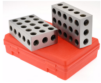
Position the Tool Setter
- Place the manual tool setter or gauge blocks on the table at the desired location.
-
Set the Z Position
- Carefully jog the spindle down until the tool tip touches the surface of the setter.
- Click Set Position.
- This records the Z position using the current spindle location and the entered Tool Setter Height value.
-
Measure Tools
- Insert each tool required for the job.
- Perform a tool measurement cycle for each tool to record its length offset.

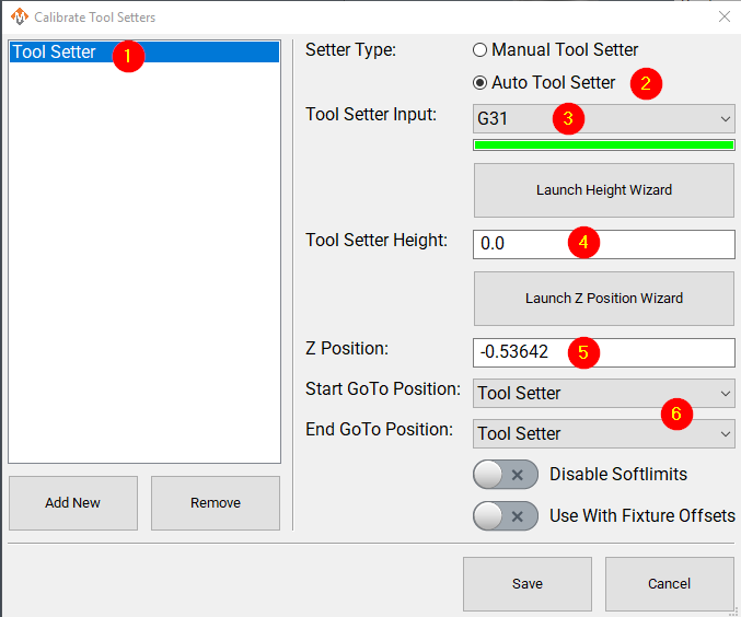
Creating an Auto Tool Setter
Click on the Tools tab at the bottom of the MachPro screen, then on the Tool Setters button in the middle of the left side of the screen.
If you are setting up a RapidChangeATC changer and setter, also refer to RapidChangeATB Tool Changer and Tool Setter
 |
 |
 |
-
Define GoTo Positions for the tool setter.
-
- Selecting a GoTo position allows the spindle to move automatically to the setter before touching off.
- This is recommended for permanently mounted setters.
- If the setter is located outside the soft limits, enable Disable Softlimits.
- Selecting a GoTo position allows the spindle to move automatically to the setter before touching off.
-
-
Click Add New to create a new tool setter.
- Enter an appropriate name for the tool setter.
-
Set the Setter Type to Auto.
-
Leave the Setter Class as Standard unless you are configuring a RapidChangeATC tool setter for stand-alone use.

-
Select the Probe Input that the tool setter is wired to. The 4 input signals available are:
- Probe (G31)
- Probe1 (G31.1)
- Probe2 (G31.2)
- Probe3 (G31.3)
-
If the correct input probe signal has been selected, then indicator bar below the input selector will turn green when the tool setter is triggered. Manually trigger the setter (or have a helper do so) to confirm the correct input is selected.
-
If the tool setter height is known, enter the value in the Tool Setter Height field.
- If the height is unknown, click Launch Height Wizard and follow the on-screen instructions to measure it.
- The tool setter must be wired to the control for this process.
-
Set the Z Position to the machine coordinate of the surface where the tool setter rests.
- If the position is unknown, use the Z Position Wizard to determine it.
- For a randomly placed setter, set the Z Position to 0.0. This value will be defined each time before measuring tools.
- See also: Using a Randomly Placed Tool Setter.
-
For randomly placed setters, leave all GoTo Position fields blank.
- Manually jog the spindle to the setter or place the setter beneath the spindle as needed.
- The machine will not perform automatic jogging during this process.

Align Tool Edge to Center of Tool Setter This feature positions the edge of the tool precisely at the center of the tool setter, ensuring accurate alignment and consistent measurement results. Pull down Configure -> Control and select the Settings Tab. Scroll down to the Measurements and Offsets section.

-
Set Tool Setter Align Tool Edge To Setter to Yes.
-
Configure the Tool Setter Align Tool Edge Offset parameter.
- Choose between Tool Radius or Tool Setter Offset as the source for the offset used to align the tool edge to the center of the setter.
-
Select whether to Align (X or Y) Axis to Setter to define which way the tool moves when aligning the edge to the center of the setter.
-
Close the Settings menu
-
If you selected Tool Setter Offset, then open the Tool Table and click the Edit option
-
Select the User Fields tab
-
Select the Tool Setter Offset field, and use the movement buttons to place the field where you want within the User Fields
-
Close the Tool Table Editor
-
Select View and select User Fields
 |
 |
Additional Settings
The measuring and offsets settings in MachPro Control may provide helpful access to these settings. Pull down Configure -> Control and select the Settings Tab and scroll down to the Measuring and Offsets portion.

| http://www.mach-labs.com | MachLabs Documentation | support@mach-labs.com |
The MachLabs Team
14518 County Road 7240, Newburg, MO 65550
support@mach-labs.com
Tool Changer Setup
Winerack Style Tool Changer Overview
The MachMotion plugin supports a wine-rack tool changing system.
It combines user-defined rack positions with a pre-programmed tool-change sequence to run a reliable tool-change routine.
The plugin includes common safety checks.
Wine-rack tool changer: a fixed array of tool holders arranged in a rack.
Tool-change sequence: predefined machine motions that pick up or return a tool.
Configure the Correct Orientation
The tool rack must be parallel to either the X-axis or the Y-axis.
The plugin works with both orientations.

-
Determine which axis the rack is parallel to (X or Y).
-
Open:
C:\Mach\Profiles\Router\ToolTables. -
Keep the file that matches your rack orientation.
-
Create an archive folder and move the other tool changer files to the archive folder. (this is not necessary but does keep things cleaner)

Select the remaining tool changer config file. it should open in libre office,
If you get this error, macros are not enabled. Follow the procedure below:
Enable Macros


Press the Macro Security button. Set security to Medium.

Restart LibreOffice. When it opens up press Enable Macros.

To confirm macros are working, when you save the file you should see this dialog and "ToolChangerData.csv" should appear or update in C:\Mach\Profiles\[PROFILE]\ToolTables.

Example: Wine-Rack Tool Changer Parallel to X
When the rack is parallel to the X-axis, use the Tool Changer X Parallel to Rack.ods file.
-
Open
C:\Mach\Profiles\Router\ToolTables. -
Keep Tool Changer X Parallel to Rack.ods.
-
Move the other tool changer files to an Archive folder.
-
Archiving is optional. It keeps the folder clean.

Edit the file with LibreOffice. In the file, there is a graphic detailing the sequence and positions.

Keep in mind, all positions are absolute and must be machine coordinate(G53) values, not work offsets. the DRO will be orange when displaying machine coordinates.
Configure the values in the Description section before editing any other parameters. The default settings are placeholders only.
Using them without adjustment can cause incorrect movements or machine crashes.

Setting Tool Pocket Positions
-
Carefully position the tool in each pocket holder.
-
Record the machine coordinate (G53) position for that pocket.
-
Enter each recorded value into the corresponding tool pocket field.
⚠️ Important: Set each pocket position individually.
Do not copy values between pockets.
Even small physical differences can cause broken tool forks.Pro Tip: don't set these up with a tool in the spindle, it is more accurate to put a tool into the tool fork, open the drawbar, and then jog the spindle onto the tool very carefully while watching the gap between the tool taper and the spindle taper and adjusting as needed.
-
Setting a pocket position to “Nil” will disable that pocket.
-
The number of active pocket positions must not exceed the number of physical pockets in the rack.

"Z Pocket (Step 3)" is the tool drop off and pick up height. this should have the tool grooves centered in the forks. If you have ISO tooling then it should work fine.
If you have HSK tooling you will probably find that the tool is picked up more easily if you set the clamp position to be a little lower than the pocket position, you'll want the spindle to be pushing down on the tool slightly. this makes your tool changes more reliable by cutting done on drawbar faults mid tool change. but this creates a problem for drop offs since it will come in little low on the forks. we can solve this by going to "ToolChangerData" tab of the spreadsheet.

This shows you all the raw tool changer positions, these get auto filled from the "configuration" page,

"ZPocketClamp" is the pickup height
"ZPocket" is the drop off height
Adjust the "ZPocketClamp" to be 0.020" or so lower than the drop off. you want some slight down pressure to fully seat the tool into the spindle nose.
After entering any positions you must save the document and the CSV conversion macro must run. You will see this dialog if it is successful in updating the settings:
All positions are exported to a .CSV file at that point. If the macro does not run when you save the file, the changed positions will not have any effect.
MachPro Settings configuration for winerack tool changers
To operate the tool changer it must be enabled in the MachPro settings.
Pull down Configure -> Control and select the Settings tab
Click the Predefined Filters button for Tool Change.
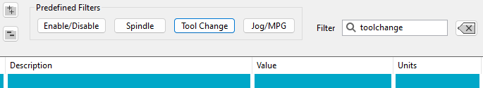
The first group of settings should match this. The number of pockets will vary from machine to machine.

Next you must decide if you want the tool changer to be outside softlimits in the active axis, if yes set "Disable softlimits" to Yes.

This means that the Y softlimits should stop the machine before the spindle reaches the winerack, this protects against crashes if an improper program is loaded. it can cause a little more headache if you get an error mid toolchange. it also means that the Y end position in the spreadsheet should be set to end the tool change back within the softlimit envelope. the yellow line below shows about where the Y softlimit should be in this case.

The next step is the signal mapping for Drawbar, airpurge, etc. there are available settings for 4 spindles. we are going to just use spindle 1 and tool changer 1 for standard single spindle machines.
the general idea is to map what you have and leave everything else blank, use Mach input and output signals, not direct I/O points. this forces everything through mach's logging which improves future troubleshooting

On a winerack tool changer you will probably only have I/O for the drawbar and maybe a dust shroud.
Here are the drawbar settings as an example.

Drawbar clamp output should be mapped to the solenoid that closes the drawbar (most machines rely on a spring stack to lock the tool, this is rarely used)
Drawbar clamped input should be mapped to the input that senses when the drawbar is retracted, usually this is "closed without tool"
Drawbar input settle time is really handy for timing, settle times are used to delay the next action in the tool change sequence, usually the output fires, then we wait for the associated input to come high, then we advance to the next thing. either the next output or a motion command. if no input is mapped the sequence will advance immediately after firing the output.
it goes like this. Output1->Input1->settle timer->Motion->Output2->input2->settle timer and so on.
Settle timers are nice if you want to wait a bit after the input goes high before advancing, or if you have no input available you can use it to wait long enough for the pneumatic action to take place before doing the next thing.
Drawbar unclamp Output should be mapped to the solenoid that opens the drawbar to release the tool virtually every machine will have this.
drawbar unclamp input should be mapped to the input that tells us that the drawbar is open and the tool can drop free.
Most winerack machines will be using these sections.


The tool release input should be mapped to a tool release button if you have one this will allow you open the drawbar manually to take tools in and out without using the tool changer. if you don't have a button then usually the F1 key on the pendant is a good option.
Pro Tip: all tool changes happen at Rapid so before testing your first tool change lower your rapid override so you have more reaction time in case something is configured incorrectly.
Carousel Style Tool Changer
The MachMotion control has built-in support for Carousel Tool Changers. It works by taking user defined positions and a pre-programmed tool changing sequence and combining them into a tool change routine. Common place safety checks are built in.
The tool changer will work with the tool changer parallel to X or Y.
The user should determine which axis the carousel is parallel to and then delete the non-applicable files located in: C:\Mach4\Profiles\Router\ToolTables
Tool Changer X Parallel to Rotary Carousel.ods
Tool Changer Y Parallel to 2 Carousels 1 Spindle.ods
Tool Changer Y Parallel to Rotary Carousel.ods
Enable Macros
If you get this error, macros are not enabled. Follow the procedure below:
In LibreOffice pull down Tools->Options->LibreOffice->Security.
Press the Macro Security button. Set security to Medium.
Restart LibreOffice. When it opens up press Enable Macros.
To confirm macros are working, when you save the file you should see this dialog and "ToolChangerData.csv" should appear or update in C:\Mach\Profiles\[PROFILE]\ToolTables.
Tool Changer Setup
Carousel tool changer example with Tool changer Carousel parallel to X shown below. In this case, you would use the Tool Changer X Parallel to Rotary Carousel.ods file and delete the unused Tool Changer files. The system will run even if the unused files are present, but it will be easier to make future modifications to the configuration without them.

Edit the file with LibreOffice. In the file, there is a graphic detailing the sequence and positions.
Keep in mind, all positions are absolute and must be machine coordinate(G53) values, not work offsets.
Configure the values in the Description section before editing any other parameters. The default settings are placeholders only.
Using them without adjustment can cause incorrect movements or machine crashes.
Set Tool Pocket Positions
-
Carefully position the tool in each pocket holder.
-
Record the machine coordinate (G53) position for that pocket.
-
Enter each recorded value into the corresponding tool pocket field.
⚠️ Important: Set each pocket position individually.
Do not copy values between pockets.
Even small physical differences can cause large alignment errors.Pro Tip: don't set these up with a tool in the spindle, it is more accurate to put a tool into the tool fork, open the drawbar, and then jog the spindle onto the tool very carefully while watching the gap between the tool taper and the spindle taper and adjusting as needed.
-
Setting a pocket position to “Nil” will disable that pocket.
-
The number of active pocket positions must not exceed the number of physical pockets in the carousel.
"Z Pocket (Step 3)" is the tool drop off height. this should have the tool grooves centered in the forks. If you have ISO tooling then it should work fine.
"Z Pocket Clamp (Step 6)" Is the tool pick up height. If you have HSK style tooling you will probably find that the tool is picked up more easily if you set the clamp position to be a little lower than the pocket position, you'll want the spindle to be pushing down on the tool slightly (about 0.02" or so) as the drawbar clamps, this makes your tool changes more reliable by cutting done on drawbar faults mid tool change.

All these entries will autofill the configuration tab which in turn get exported upon save to a CSV which the tool change program uses.
This shows you all the raw tool changer positions, this is where you can modify data for custom applications before saving.
After entering any positions, you must save the document, and the CSV conversion macro must run. You will see this dialog if it is successful in updating the settings:
All positions are exported to a . CSV file at that point. If the macro does not run when you save the file, the changed positions will not have any effect.
MachPro Settings configuration for winerack tool changers
To operate the tool changer it must be enabled in the MachPro settings.
Pull down Configure -> Control and select the Settings tab
Click the Predefined Filters button for Tool Change.
The first group of settings should match this. The number of pockets will vary from machine to machine.

Next you must decide if you want the tool changer to be outside softlimits in the active axis, if yes set "Disable softlimits" to Yes.
This means that the X softlimits should stop the machine before the spindle reaches the carousel, this protects against crashes if an improper program is loaded. it can cause a little more headache if you get an error mid toolchange. it also means that the X end position in the spreadsheet should be set to end the tool change back within the softlimit envelope. the yellow line below shows about where the X softlimit should be in this case.

The next step is the signal mapping for Drawbar, airpurge, etc. there are available settings for 4 spindles. we are going to just use spindle 1 and tool changer 1 for standard single spindle machines.
the general idea is to map what you have and leave everything else blank, use Mach input and output signals, not direct I/O points. this forces everything through mach's logging which improves future troubleshooting
On a Carousel tool changer you will probably have I/O for the drawbar, carousel and maybe a dust shroud.
Here are the drawbar settings as an example.
Drawbar clamp output should be mapped to the solenoid that closes the drawbar (most machines rely on a spring stack to lock the tool, this is rarely used)
Drawbar clamped input should be mapped to the input that senses when the drawbar is retracted, usually this is "closed without tool"
Drawbar input settle time is really handy for timing, settle times are used to delay the next action in the tool change sequence, usually the output fires, then we wait for the associated input to come high, then we advance to the next thing. either the next output or a motion command. if no input is mapped the sequence will advance immediately after firing the output.
it goes like this. Output1->Input1->settle timer->Motion->Output2->input2->settle timer and so on.
Settle timers are nice if you want to wait a bit after the input goes high before advancing, or if you have no input available you can use it to wait long enough for the pneumatic action to take place before doing the next thing.
Drawbar unclamp Output should be mapped to the solenoid that opens the drawbar to release the tool virtually every machine will have this.
drawbar unclamp input should be mapped to the input that tells us that the drawbar is open and the tool can drop free.
Most Carousel machines will be using these sections.
If you have a carousel that moves on an air cylinder then use the section below, in yellow are the commonly used settings.

The tool release input should be mapped to a tool release button if you have one this will allow you open the drawbar manually to take tools in and out without using the tool changer. if you don't have a button then usually the F1 key on the pendant is a good option.
Pro Tip: all tool changes happen at Rapid so before testing your first tool change lower your rapid override so you have more reaction time in case something is configured incorrectly.
Auto Tool Changer Manual Override
Auto Tool Changer Manual Override is used when you have a tool that doesn't fit in the tool changer magazine and needs to be manually loaded and unloaded from the spindle.
Enable User Fields in the Tool Table
- Edit Configure -> Settings
- FIlter for Tool Changer and then set the Tool Changer Method to Auto

- Open the tool table
- Under the View menu, select User Fields and the Tool Changer Override column will be displayed.
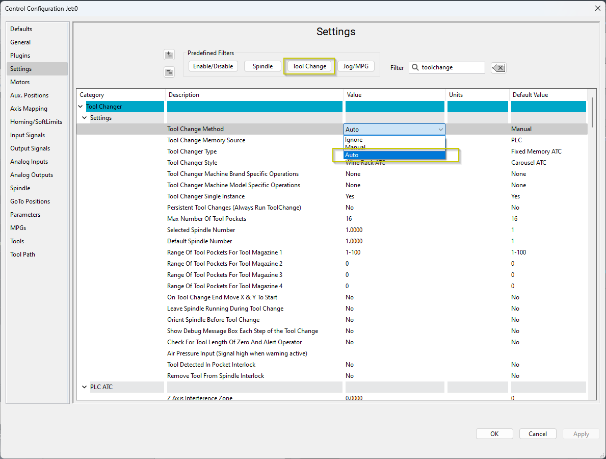
This column will only be enabled if the Tool Changer Method is set to Auto
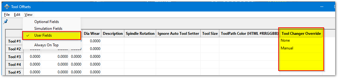
Your options are to leave it blank, or select None (no override) or select Manual for tools that you will be manually loading into the spindle.
Operation
When executing a Tool Changer Override the Tool Change sequence is a bit of a hybrid between a Auto Tool Change and a Manual Tool Change sequence.
If the Spindle is loaded with a Tool from the Tool Magazine it will drop off that tool into the magazine and then move to the Manual Tool Change location and wait for the operator to manually load the tool into the spindle. The operator will need to open and close the draw bar using the Tool Release Button.
When the Tool needs to be manually loaded this is the dialog that will appear.

If the Spindle is loaded with a Tool that is configured for Manual this dialog will appear. The operator will need to open and close the draw bar using the Tool Release Button to remove the tool from the spindle.
When the Tool needs to be manually Unloaded this is the dialog that will appear.

When the Tool needs to be manually Unloaded and then the new tool manually loaded this is the dialog that will appear.

Configure the Location for Manual Tool Changes
Configure a "GoTo Position" for the location you want the machine to move to when the operator loads and unloads the tool into the spindle.
Follow this link for more information on how to setup GoTo Positions.
Make sure the check box named "Use as Tool Change position (P1)" is checked.
Configure the Highest allowed Tool Number
Go to Configure>Control>Tools
Change the "Max Tools" value to whatever your highest tool number.

Add New Tool Range
It is possible to Override a tool that is mapped to a Tool Pocket, but this would waste that Tool Pocket because the machine will never try to use it.
The advised way of using this feature would be to modify the ToolInfo.lua and setup an additional group/range of tools that are not assigned to Tool Pockets.
Open the following file in Notepad ++ "C:\Mach4\Profiles\"Your Profile Name"\ToolTables\ToolInfo.Lua"
Default Configuration:
----- Tool Configuration Info -----
-- Global Variables --
-- Production needs to configure these variables before shipping
TOOL_NAMES = {
	{["Name"] = "Spindle Empty", ["Start"] = 0, ["End"] = 0, ["UseToolPocket"] = 1},
	{["Name"] = "Spindle (1)", ["Start"] = 1, ["End"] = 99, ["UseToolPocket"] = 1},
	{["Name"] = "Spindle (2)", ["Start"] = 100, ["End"] = 100, ["UseToolPocket"] = 0},
	{["Name"] = "Spindle (3)", ["Start"] = 999, ["End"] = 999, ["UseToolPocket"] = 0},
	{["Name"] = "Spindle (4)", ["Start"] = 999, ["End"] = 999, ["UseToolPocket"] = 0},
	{["Name"] = "Saw (1)", ["Start"] = 999, ["End"] = 999, ["UseToolPocket"] = 0},
	{["Name"] = "Saw (2)", ["Start"] = 999, ["End"] = 999, ["UseToolPocket"] = 0},
	{["Name"] = "Drill Bank (1)", ["Start"] = 999, ["End"] = 999, ["UseToolPocket"] = 0},
	{["Name"] = "Drill Bank (2)", ["Start"] = 999, ["End"] = 999, ["UseToolPocket"] = 0},
	{["Name"] = "Laser", ["Start"] = 250, ["End"] = 250, ["UseToolPocket"] = 0}
}
New row added with a range of Tool numbers starting from Tool #100 to Tool #199 with the option "UseToolPocket" set to 0.
----- Tool Configuration Info -----
-- Global Variables --
-- Production needs to configure these variables before shipping
TOOL_NAMES = {
	{["Name"] = "Spindle Empty", ["Start"] = 0, ["End"] = 0, ["UseToolPocket"] = 1},
	{["Name"] = "Spindle (1)", ["Start"] = 1, ["End"] = 99, ["UseToolPocket"] = 1},
    {["Name"] = "Spindle (1) Manual", ["Start"] = 100, ["End"] = 199, ["UseToolPocket"] = 0},
	{["Name"] = "Spindle (2)", ["Start"] = 100, ["End"] = 100, ["UseToolPocket"] = 0},
	{["Name"] = "Spindle (3)", ["Start"] = 999, ["End"] = 999, ["UseToolPocket"] = 0},
	{["Name"] = "Spindle (4)", ["Start"] = 999, ["End"] = 999, ["UseToolPocket"] = 0},
	{["Name"] = "Saw (1)", ["Start"] = 999, ["End"] = 999, ["UseToolPocket"] = 0},
	{["Name"] = "Saw (2)", ["Start"] = 999, ["End"] = 999, ["UseToolPocket"] = 0},
	{["Name"] = "Drill Bank (1)", ["Start"] = 999, ["End"] = 999, ["UseToolPocket"] = 0},
	{["Name"] = "Drill Bank (2)", ["Start"] = 999, ["End"] = 999, ["UseToolPocket"] = 0},
	{["Name"] = "Laser", ["Start"] = 250, ["End"] = 250, ["UseToolPocket"] = 0}
}
This is the line that was added:
{["Name"] = "Spindle (1) Manual", ["Start"] = 100, ["End"] = 199, ["UseToolPocket"] = 0},
Now you should be configured to allow Tool calls using M6 T100 - M6 T199 for manual Tool Changes.
Global Monitoring System (GMS)
Configure the Global Monitoring System
Global Monitoring is used to setup user alerts or messages as well as to control I/O functionality based on certain conditions. The system allows the machine to watch for specified conditions, and take action when those conditions are met.
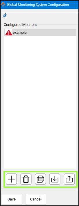
To set up the Global Monitoring System go to Configuration -> Plugins -> Global Monitoring System.

Working with configured monitors
|
The monitoring system provides five main functions for managing monitors: 1. Create a Monitor
2. Delete a Monitor
3. Duplicate a Monitor
4. Import Monitors
5. Export Monitors
Active Monitor The monitor selected in the leftmost list is the one currently active for editing. |
 |
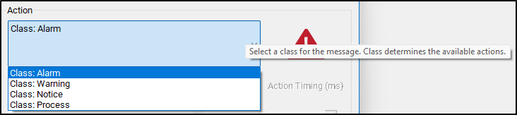
Configure Monitor Class
The monitoring system can initiate four classes of actions: Alarm, Warning, Notice, and Process.
Each class defines how the system responds to detected conditions.
1. Alarm
-
Used for emergency conditions.
-
Can take immediate safety actions, such as:
-
Disabling the machine.
-
Stopping all motion.
-
-
Requires operator intervention before restarting.
2. Warning
-
Used for non-critical issues that still require attention.
-
Can perform various automated actions.
-
Prevents Cycle Start while active.
-
Alerts the operator through a visible or audible signal.
3. Notice
-
Used for informational messages only.
-
Takes no automatic actions.
-
Displays a message to the operator for awareness.
4. Process
-
Used for background control actions.
-
Has the same potential actions as a Warning,
but does not alert the operator and does not block Cycle Start.
Tip: Use Alarm for safety-critical faults, Warning for operational issues, Notice for information, and Process for silent automation tasks.
 Configure Monitor Actions
After selecting the Action Class, you can define the specific action the monitor performs when it becomes active.
Primary and Secondary Actions
-
Each monitor has one primary action.
-
Some actions allow a secondary action.
-
Example:
-
A Warning with Action: Escalate to Alarm can trigger a chosen Alarm action after a delay.
-
-
Action Timing
-
The Action Timing field defines the delay (in milliseconds) between the first and second actions.
Example:
If Action Timing = 5000, the secondary action runs 5 seconds after the primary action.If Action Timing = 1, the secondary action runs 1/1000 of a second after the primary action - and that is very short
Set longer rather than shorter timings. It is possible to overwhelm your computer with timings that are too short. For actions that need a quick response, start with 500 and only decrease if you need to.
Repeating Actions
-
You can configure the monitor to repeat actions while it remains active.
-
When enabled:
-
The monitor executes the first action.
-
Waits for the defined Action Timing period.
-
Executes the second action (if configured).
-
Repeats this cycle until the monitor condition is no longer active.
-
Tip: Use repeating actions for persistent conditions that require continuous alerts or repeated control signals.

Custom Monitor Actions
If the standard actions do not meet your needs, you can create custom actions for the Warning and Process classes.
Enabling Custom Actions
-
In the Action List, select Custom.
-
Click the Customize button next to the action field.
-
This button is only active when Custom is selected.
-
-
A Custom Action Editor window will open.
Building a Custom Action List
In the Custom Action Editor, you can define a sequence of actions that occur when the monitor activates.
Steps:
-
Select an Action Type – Choose what kind of task the monitor will perform.
-
Fill in Action Details – Provide required parameters or settings.
-
Press Add Action – Adds the defined action to the custom action list.
Managing the Action List
-
Reorder actions:
Select an item and use the up or down arrow buttons to change its order. -
Remove an action:
Select it and press the red X button.
The monitor will execute the actions in the listed order each time it is activated.


An item can be double-clicked on to be edited, and then you should press Update Action to save your changes.
Items will be resolved sequentially in the order they appear in the list, with no pauses in between items.
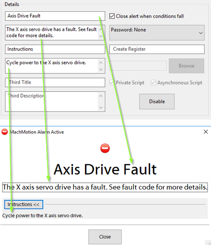
Monitor Details
Most monitors display an alert when their conditions are triggered.
All alert information and related settings are managed in the Details section of the monitor configuration.
Alert Information
-
The Details section controls what information appears in the alert message when the monitor activates.
-
You can edit titles, messages, and other displayed text from this section.
Password Protection
-
You can password-protect a monitor from the Details section.
-
When enabled:
-
The password is required to edit the monitor.
-
The password is also required to clear the monitor after activation.
-
Register Output
-
The monitor can write its current status to a register.
-
The register includes:
-
Enabled/Disabled state.
-
Idle/Active state.
-
-
Use this to track monitor states through external systems or scripts.
Script Execution
-
If the selected action is Execute Script, configure the script in this section.
-
Specify the script file name with the
.mcsextension.-
Example:
MonitorAlert.mcs
-
Disabling a Monitor
-
You can disable the entire monitor without deleting it.
-
A disabled monitor will:
-
Not check its conditions.
-
Not perform any actions.
-
-
Re-enable it later to restore normal operation.


Set Monitor Conditions
A monitor will do its configured action based on the conditions that are set for it. To edit these conditions, you will need to select the Edit Conditions button. The following window will be displayed.

Monitor conditions define when a monitor becomes active.
They are organized into sets and items, which together form the logical rules that trigger a monitor.
Structure Overview
-
Sets: Groups that define the logical relationship between their items or subsets.
-
Items: Individual conditions within a set.
-
Subsets: Nested sets that allow complex logical combinations.
Set Types
Each set can be one of three logic types:
Set Type Logic Description AND True only if all contained items and subsets are true. OR True if at least one item or subset is true. NOT True only if all contained items and subsets are false. Tip: Most monitors only require a single AND set.
Adding Sets
-
Select the parent set where the new set should belong.
-
Choose the set type (AND, OR, or NOT) from the list.
-
Press Add Set.
This creates a new logic group inside the parent set.
Adding Items (Conditions)

-
Select an item type from the dropdown menu.
-
Fill in the condition details.
-
Press Add Condition to include it in the selected set.
Example: Machine Enabled Condition
To add a condition that requires the machine to be enabled:
-
Choose Condition Type: Signal.
-
Select Output Signals.
-
Choose Machine Enabled.
-
Press Add Condition.
Editing Sets and Conditions
-
Edit a set:
Double-click the set in the left-hand list, change the set type, then press Update. -
Edit a condition:
Double-click the condition, modify the details, then press Update.
Saving Changes
-
Press OK to save all modifications.
-
Press Cancel to discard any unsaved changes.

Save All Changes
Pressing Save will save changes to all monitors and exit config. Pressing Cancel will discard all changes and exit config.

Common GMS Templates
See the attached ini files to download and import standard GMS functions.
SpindleWarmupBackup.ini
If you run a file when the spindle is not warmed up, it will warm up the spindle and then go ahead and run the file. As a safety feature, you can prevent a file from starting until spindle warmup is completed to avoid this issue.
Diagnostics Window
The Global Monitoring System icon is on most screens, and will indicate if there is currently an alarm or warning active. If there are no alarms or warnings active, then the icon will be a green checkmark. If there is an alarm or warning active, it will flash a red and yellow error triangle. Clicking on the icon will open the diagnostics window.


The diagnostics window will show all configured monitors and their data. The condition tree will show the state of each condition by highlighting true conditions in green. A red condition means that the condition is incorrectly configured and cannot be checked.
Alarms and warnings must be cleared to operate the machine. Pressing Reset on the operator panel will clear alarms. They can also be cleared in the diagnostics be clicking Clear All. Resetting a monitor will transition the monitor back to the idle state and reset the timers on all conditions. If the conditions on a monitor are still true, then the monitor will activate again immediately.
A monitor can be temporarily disabled here. The monitor will continue to check it's conditions and change states, but will not take any actions when it transitions out of the idle state. The monitor will re-enable itself when it transitions back to idle state or when the operator enables it again.

-


View and Modify MachPro Settings
Now you can view and edit any of the Settings. Use the Predefined Filters or enter your own search terms in the Filter box.

The Settings tab options are listed below. Many of the settings are defined per axis or motor. If the settings are the same for all instances, then they will only be described one time.
| Level 1 Category | Level 2 Category | Description | Constraints | Default Value | Units |
| Absolute Encoders | Enabled | Absolute Encoders HiCON Enabled | No | ||
| Motor | Absolute Encoder Enabled Motor | No | |||
| Encoder Counts Per Rev Motor | 16384 | ||||
| Origin Offset Counts Motor | 0 | ||||
| Preferences | Backup | Backup Location | C:\\MachMotion Backup | ||
| Automatically Backup Files | Yes | ||||
| Automatic Backup Interval | min:0, max:365 | 10 | Days | ||
| Retain Backup Count | min:0, max:1000 | 10 | |||
| Automatically Backup Application | Yes | ||||
| Automatic Application Backup Interval | min:0, max:730 | 10 | Days | ||
| Retain Application Backup Count | min:0, max:1000 | 5 | |||
| Preferences | Screen | Blended Velocity Averaging | min:0, max:20 | 5 | |
| Hide the Title Bar in Mach4GUI | No | ||||
| Retain Mach Override Values On Shutdown | No | ||||
| Preferences | Software | Block Delete Levels Enabled | Level 0, Levels 0-9 | Level 0 | |
| Enable OEM Gcode Subs | No | ||||
| Preferences | Dialogs | Enable Confirmation Dialogs | Yes/No | Yes | |
| Warning Message Timeout | min:0, max:1000 | 3 | Seconds | ||
| Preferences | GCAdapter | Enable GCAdapter | No | ||
| Preferences | End Of Program | End Of Program Output (M30) | |||
| End Of Program Output Time On (> 0) | 0 | Seconds | |||
| GCode File Repeat Enabled | No | ||||
| Preferences | File Resume | File Resume Mode | Advanced, Simplifed | Advanced | |
| File Resume XY Reposition Feedrate | 250 | ||||
| File Resume Z Reposition Feedrate | 100 | ||||
| Preferences | GCode | Path To GCode Shortcut 1 | |||
| Path To GCode Shortcut 2 | |||||
| Path To GCode Shortcut 3 | |||||
| Preferences | Debugging | Enable Debugging | No | ||
| Start Logging On Screen Load | No | ||||
| Save Session Log | No | ||||
| Control LoadAllModules Behavior | 0 | ||||
| Preferences | Limit Switch | Limit Switch Alarm Enabled | Yes | ||
| Preferences | Tool Path | ToolPath File Limits Mode | Part Coordinates, Machine Coordinates | Part Coordinates | |
| Auto Regen ToolPath | No | ||||
| ToolPath Zoom Limit Max | min:1, max:100000 | 1000 | |||
| ToolPath Zoom Limit Min | min:0, max:1 | 0 | |||
| ToolPath Show Machine Boundaries | Yes | ||||
| Preferences | Limit Override | Disable Limit Override when limits cleared | Yes | ||
| Preferences | Watchdog | Start Delay | min:0, max:300 | 120 | Seconds |
| Error Threshold | min:0, max:60000 | 10000 | Milliseconds | ||
| Start Delay (Low Priority) | min:0, max:300 | 180 | Seconds | ||
| Error Threshold (Low Priority) | min:0, max:60000 | 30000 | Milliseconds | ||
| Watchdog Interval | min:500, max:60000 | 500 | Milliseconds | ||
| ArcPro | Anti-Dive | Anti-Dive Feedrate (FR) | min:0, max:100 | % | 50 |
| Anti-Dive | Anti-Dive Tip Voltage Operating Range | min:0, max:100 | % | 50 | |
| Anti-Dive | Anti-Dive Tip Voltage Recovery Range | min:0, max:100 | % | 50 | |
| Softlimits | Startup | Auto Enable SoftLimits | No, Homing, Startup | Homing | |
| Measuring and Offsets | Measuring and Offsets | Edge Finder Diameter | min:0, max:100000 | 0 | Units |
| Auto Enable Tool Length Offset | Yes | ||||
| Enable Tool Length Verify | No | ||||
| Tool Length Verify Mode | Verify Length, Verify Difference | Verify Length | |||
| Measuring and Offsets | Auto Tool Setter | Tool Setter Approach Speed | min:0, max:100000 | 100 | Units/Min |
| Tool Setter Touch-Off Speed | min:0, max:100000 | 10 | Units/Min | ||
| Tool Setter Back-Off Distance | min:0, max:100000 | 0.1 | Units | ||
| Tool Setter Clearance Height | min:0, max:100000 | 1 | Units | ||
| Tool Setter Touch-Off Cycles | One Touch, Average Three Touches | One Touch | |||
| Tool Setter Disable SoftLimits | No | ||||
| Tool Setter Align Tool Edge To Setter | No | ||||
| Tool Setter Align Tool Edge Offset | Tool Radius, Tool Setter Offset | Tool Radius | |||
| Tool Setter Align (X or Y) Axis To Setter | X Positive, X Negative, Y Positive, Y Negative | X Positive | |||
| Tool Setter Enable Output Selection | |||||
| Tool Setter Error Input Selection | |||||
| Tool Setter Probe Position Source | Minimum Soft Limit, Tool Setter Probe Position | Minimum Soft Limit | |||
| Tool Setter Probe Position | 0 | Units | |||
| Measuring and Offsets | Probing | Probe Enable Output Selection | |||
| Probe Error Input Selection | |||||
| Measuring and Offsets | Measuring and Offsets (Screen V1) | Tool Setter Type (V1 Screen) | Manual, Auto | Manual | |
| Measuring and Offsets | Tool Specific Soft Limits | Tool Specific Soft Limits Enabled | No | ||
| Shape Cutting | Cut Recovery | Cut Recovery Re-Position Axis Selection | 0-5 | Axis IDs | |
| Shape Cutting | General | Enabled Rip Cut Directions | 4, 8 | 8 | |
| General | Enabled Jogging Directions | 4, 8 | 8 | ||
| General | Show Machine Boundaries | No | |||
| General | Jog Follow Mode | No | |||
| General | On Path Tolerance | min:0.0, max:99999.0 | Inch/MM | 0.001 | |
| General | Breakaway Input | IO$HiCON$P11 Input 2 | |||
| Shape Cutting | Machine Options | Plasma Style | Not Used, Servo Height Control, Roller Head | ||
| Machine Options | Oxy Fuel Type | Not Used, Servo Height Control, Manual Height Control | |||
| Machine Options | Marker Type | Not Used, Plate Marker | |||
| Machine Options | Drill Type | Not Used, Automatic Drill, Servo Drill | |||
| Shape Cutting | Plasma | THC Disable Output | IO$HiCON$P11 Output 6 | ||
| Plasma | Plasma Flame Off Output | IO$HiCON$P11 Output 7 | |||
| Plasma | Plasma Error Input | IO$HiCON$P11 Input 1 | |||
| Plasma | Vent Output | ||||
| Plasma | Lost Arc Tolerance | min:0.1, max:1000.0 | 0.5 | ||
| Shape Cutting | Plasma Roller Head | Plasma Roller Head Down Time Delay | min:0.0, max:10000.0 | ms | 1000 |
| Plasma Roller Head | Plasma Roller Head Torch Output | IO$HiCON$P11 Output 3 | |||
| Plasma Roller Head | Plasma Roller Head Down Output | IO$HiCON$P11 Output 4 | |||
| Plasma Roller Head | Plasma Roller Head Arc OK Input | IO$HiCON$P11 Input 3 | |||
| Shape Cutting | Oxy Fuel | Oxy Fuel Allow Movement On Pierce | No | ||
| Oxy Fuel | Oxy Fuel Heads | 1,2,3,4 | 4 | ||
| Oxy Fuel | Auto Ignition | ms/unit | No | ||
| Oxy Fuel | Auto Ignition Time | min:0.0, max:10000.0 | 500 | ||
| Oxy Fuel | Oxy MilliSeconds Per Unit | min:0.0, max:10000.0 | ms/unit | 100 | |
| Oxy Fuel | Oxy Enable 1 Output | OutputSignal$1060 | |||
| Oxy Fuel | Oxy 1 Up Output | OutputSignal$1061 | |||
| Oxy Fuel | Oxy 1 Down Output | OutputSignal$1062 | |||
| Oxy Fuel | Ignition Relay Output | ` | OutputSignal$1066 | ||
| Oxy Fuel | Oxy Ignition Output | OutputSignal$1067 | |||
| Oxy Fuel | Cutting Gas Output | OutputSignal$1068 | |||
| Oxy Fuel | Preheat Oxy Output | OutputSignal$1069 | |||
| Oxy Fuel | Cutting Oxy 1 Output | OutputSignal$1070 | |||
| Shape Cutting | Plate Marker | Plate Marker Output | IO$HiCON$P11 Output 0 | ||
| Shape Cutting | Drill | Drill Use Coolant | Yes | ||
| Drill | Drill Up Output | IO$HiCON$P11 Output 1 | |||
| Drill | Drill Down Output | IO$HiCON$P11 Output 2 | |||
| Drill | Drill Up Input | ||||
| Drill | Drill Foot Down Output | ||||
| Shape Cutting | Laser | Laser Output | |||
| Machine | Startup | Auto Load Last Gcode | No | ||
| Enable and Home Startup Dialog | Yes | ||||
| Machine | Enable | Hardware Enable Time Out | min:100, max:30000 | 5000 | Milliseconds |
| Hardware Enable | |||||
| Drive Enable | |||||
| Drive Enable Delay | min:0, max:2000 | 500 | Milliseconds | ||
| Automatically Configure Enable Parameters | Yes | ||||
| Turn Off Enable Signals Upon Disable | No, "Drive Enable", "Drive & Hardware Enable" | Drive & Hardware Enable | |||
| Machine | Soft Limits | Cycle Start Soft Limit Recovery | No | ||
| Machine | Stop | Ignore Auxillary Buttons On Stop | min:1, max:6 | Auxiliary Button # | |
| Ignore Outputs On Stop | min:1, max:63 | Output Signal # | |||
| Machine | Disable | Ignore Outputs On Disable | min:1, max:63 | Output Signal # | |
| Ignore Outputs On Emergency Stop | min:1, max:63 | Output Signal # | |||
| Machine | Jogging | Inhibit Jogging When Not Homed | No | ||
| Jogging | Axes | A/U Axis Rotary | min:0,max:1 | 0 | |
| B/V Axis Rotary | min:0,max:1 | 0 | |||
| C/W Axis Rotary | min:0,max:1 | 0 | |||
| OB(1) Axis Rotary | min:0,max:1 | 0 | |||
| OB(2) Axis Rotary | min:0,max:1 | 0 | |||
| OB(3) Axis Rotary | min:0,max:1 | 0 | |||
| OB(4) Axis Rotary | min:0,max:1 | 0 | |||
| OB(5) Axis Rotary | min:0,max:1 | 0 | |||
| OB(6) Axis Rotary | min:0,max:1 | 0 | |||
| Jogging | Jogging | Incremental Jog Acceleration | min:1, max:100 | 10 | % |
| Max Incremental Jog Velocity % | min:1, max:100 | 100 | % | ||
| Continuous Jog Acceleration | min:1, max:100 | 100 | % | ||
| External Jog Acceleration | min:1, max:100 | 100 | % | ||
| External Jog Rate | min:1, max:100 | 100 | % | ||
| External Jog Increment | min:.0001,max:100,precision:4 | 0.001 | units | ||
| Jog Increment X1 for Rotary Axes | min:0,max:1000 | 0.01 | units | ||
| Jog Increment X10 for Rotary Axes | min:0,max:1000 | 0.1 | units | ||
| Jog Increment X100 for Rotary Axes | min:0,max:1000 | 1 | units | ||
| Jog Increment X1000 for Rotary Axes | min:0,max:1000 | 10 | units | ||
| Jog Increment X10000 for Rotary Axes | min:0,max:1000 | 100 | units | ||
| Jogging | MPG | MPG Max Jog Velocity % | min:1, max:100 | 100 | |
| MPG Counts per Detent | min:1, max:100 | 4 | |||
| MPG Jog Increment X1 Acceleration | min:1, max:100 | 1 | |||
| MPG Jog Increment X10 Acceleration | min:1, max:100 | 5 | |||
| MPG Jog Increment X100 Acceleration | min:1, max:100 | 50 | |||
| Rotary Feedrate Mode | Axes | A Axis Rotary Feedrate Mode | Slave of XYZ, Constant Surface Speed | Slave of XYZ | |
| B Axis Rotary Feedrate Mode | Slave of XYZ, Constant Surface Speed | Slave of XYZ | |||
| C Axis Rotary Feedrate Mode | Slave of XYZ, Constant Surface Speed | Slave of XYZ | |||
| Azure Label | Enabled | Azure Label Software Enabled | No | ||
| Label | Default Label ID for Azure Label | 0 | |||
| URL | URL for AzureAPI | http://localhost:42103/api/v1 | |||
| Barcode | Scanner | Barcode Scanner Enabled | No | ||
| Scanner | Barcode Scanner Com Port | COM1, COM2, COM3, COM4, COM5, COM6, COM7, COM8, COM9, COM10, COM11, COM12, COM13, COM14, COM15, COM16 | COM1 | ||
| Barcode Scanner Mode | Load GCode Files, Generic Reader | Load GCode Files | |||
| Barcode Scanner Use Selected Instance | Yes | ||||
| Barcode | GCode | Barcode Scanner Load GCode Directory (When blank uses GCode Folder) | |||
| Modes | Constant Velocity | Whether or not to use CV/VB | Yes | ||
| Path Error Tolerance | min:0, precision:5 | 0.0001 | |||
| Axes to include in CV/VB calculations (combinations of X Y and Z) | X; Y, X; Y; Z, , X; Z, X, Y, Z, Y; Z, | X;Y | Axis Letter | ||
| Modes | Interrupt | Interrupt Enabled | Yes | ||
| Interrupt Retract Machine Position (G53) | min:0 | 0 | Inch/MM | ||
| Interrupt Fast Reposition Feedrate | min:0 | 25 | Inch/MM | ||
| Interrupt Slow Reposition Feedrate | min:0 | 0.25 | Inch/MM | ||
| Interrupt Backup Lines | min:0, max:500 | 2 | Lines | ||
| Interrupt Activate Pound Number | min:200, max:999 | 600 | |||
| Interrupt Clearance Position Pound Number | min:200, max:999 | 601 | |||
| Modes | Manual Mode | Manual Mode Enabled | No | ||
| Manual Mode Axis To Disable | min:1, max:63 | 63 | |||
| Modes | Retract | Retract Enabled | No | ||
| Retract GoTo Positions Enabled | No | ||||
| Retract Activate Pound Number | min:0, max:999 | 0 | |||
| Retract Entry GCode String | |||||
| Retract Subroutine Number | min:1, max:99999 | 8002 | |||
| Tool Changer | Settings | Tool Change Method | Ignore, Manual, Auto | Manual | |
| Tool Change Memory Source | PLC, Mach | PLC | |||
| Tool Changer Type | Fixed Memory ATC, Random Memory ATC | Fixed Memory ATC | |||
| Tool Changer Style | Carousel ATC, Multiple Carousels 1 Spindle, Multiple Magazines And Spindles Unique Pocket Numbers, Multiple Magazines And Spindles Identical Pocket Numbers, Wine Rack ATC | Carousel ATC | |||
| Tool Changer Machine Brand Specific Operations | None, KOMO | None | |||
| Tool Changer Machine Model Specific Operations | None, KOMO Pneumatic Tool Changer | None | |||
| Tool Changer Single Instance | Yes | ||||
| Persistent Tool Changes (Always Run ToolChange) | No | ||||
| Max Number Of Tool Pockets | min:1, max:254 | 16 | |||
| Current Tool Pocket Register | |||||
| Selected Spindle Number | 1 | ||||
| Default Spindle Number | 1 | ||||
| Range Of Tool Pockets For Tool Magazine 1 | 1-100 | ||||
| Range Of Tool Pockets For Tool Magazine 2 | 0 | ||||
| Range Of Tool Pockets For Tool Magazine 3 | 0 | ||||
| Range Of Tool Pockets For Tool Magazine 4 | 0 | ||||
| On Tool Change End Move X & Y To Start | No | ||||
| Leave Spindle Running During Tool Change | No | ||||
| Show Debug Message Box Each Step of the Tool Change | No | ||||
| Check For Tool Length Of Zero And Alert Operator | No | ||||
| Air Pressure Input (Signal high when warning active) | |||||
| Tool Detected In Pocket Interlock | No | ||||
| Tool Changer | Modify Z Offsets | Enable Modify Z Offsets During Tool Change | No | ||
| Modify Z Offsets Default Selection | On, Off | Off | |||
| Tool Changer | Mach ATC | Enable Tool In Spindle GMS Monitoring | Yes | ||
| Sensor Timeout | min:1, max:100000 | 20000 | Milliseconds | ||
| Disable SoftLimits | No | ||||
| Tool Changer | Spindle Slide | Spindle Settle Time | min:0, max:100000 | 0 | Milliseconds |
| Tool Changer | Spindle Slide 1 | Spindle Up Output | |||
| Spindle Down Output | |||||
| Spindle Up Input | |||||
| Spindle Down Input | |||||
| Tool Changer 1 | Spindle Drawbar 1 | Draw-Bar Clamped Input | |||
| Spindle Drawbar 1 | Draw-Bar Clamp Output | ||||
| Spindle Drawbar 1 | Draw-Bar UnClamped Input | ||||
| Spindle Drawbar 1 | Draw-Bar UnClamp Output | ||||
| Spindle Drawbar 1 | Draw Bar Input Settle Time | min:0, max:100000 | 0 | Milliseconds | |
| Tool Changer 1 | Spindle 1 | Wait For Spindle To Stop Input | InputSignal$182 | ||
| Spindle 1 | Tool In Spindle Input | ||||
| Spindle 1 | Tool Locked Input | ||||
| Spindle 1 | Tool In Pocket Input | ||||
| Spindle 1 | Tool Release Button Input | InSig,OutSig | |||
| Spindle 1 | Tool Release Button Indicator Output | ||||
| Spindle 1 | Spindle Move To Tool Change Zone Input | ||||
| Spindle 1 | Spindle Move To Tool Change Zone Output | ||||
| Spindle 1 | Spindle Move To Tool Change Zone Settle Time | min:0, max:100000 | 0 | Milliseconds | |
| Spindle 1 | Spindle Move To Cutting Zone Input | ||||
| Spindle 1 | Spindle Move To Cutting Output | ||||
| Spindle 1 | Spindle Move To Cutting Settle Time | min:0, max:100000 | 0 | Milliseconds | |
| Spindle 1 | Air Purge Output | ||||
| Tool Changer 1 | Carousel 1 | Carousel Rotation Strategy | Shortest Path, Fixed Direction | Shortest Path | |
| Carousel 1 | Carousel Engaged Interlock | No | |||
| Carousel 1 | Carousel Jog To Next Pocket Input | ||||
| Carousel 1 | Carousel Jog To Previous Pocket Input | ||||
| Carousel 1 | Carousel Move Up To Park Input | ||||
| Carousel 1 | Carousel Move Up To Park Output | ||||
| Carousel 1 | Carousel Move Up To Park Settle Time | min:0, max:100000 | 0 | Milliseconds | |
| Carousel 1 | Carousel Move Down To Tool Pocket Input | ||||
| Carousel 1 | Carousel Move Down To Tool Pocket Output | ||||
| Carousel 1 | Carousel Move Down To Park Settle Time | min:0, max:100000 | 0 | Milliseconds | |
| Carousel 1 | Carousel Move Away To Parked Input | ||||
| Carousel 1 | Carousel Move Away To Parked Output | ||||
| Carousel 1 | Carousel Move Away To Parked Settle Time | min:0, max:100000 | 0 | Milliseconds | |
| Carousel 1 | Carousel Move To Engaged Input | ||||
| Carousel 1 | Carousel Move To Engaged Output | ||||
| Carousel 1 | Carousel Move To Engaged Settle Time | min:0, max:100000 | 0 | Milliseconds | |
| Carousel 1 | Carousel Move To Tool Clearance On Input | ||||
| Carousel 1 | Carousel Move To Tool Clearance On Output | ||||
| Carousel 1 | Carousel Move To Tool Clearance On Settle Time | min:0, max:100000 | 0 | Milliseconds | |
| Carousel 1 | Carousel Move To Tool Clearance Off Input | ||||
| Carousel 1 | Carousel Move To Tool Clearance Off Output | ||||
| Carousel 1 | Carousel Move To Tool Clearance Off Settle Time | min:0, max:100000 | 0 | Milliseconds | |
| Tool Changer 1 | Dust Cover 1 | Dust Cover Up-Open Output | |||
| Dust Cover 1 | Dust Cover Up-Open Input | ||||
| Dust Cover 1 | Dust Cover Up-Open Input Settle Time | min:0, max:100000 | 0 | Milliseconds | |
| Dust Cover 1 | Dust Cover Down-Close Output | ||||
| Dust Cover 1 | Dust Cover Down-Close Input | ||||
| Dust Cover 1 | Dust Cover Down-Close Input Settle Time | min:0, max:100000 | 0 | Milliseconds | |
| Tool Changer | PLC ATC | Z Axis Interference Zone Enabled | Yes | ||
| PLC ATC | Z Axis Interference Zone | min:0, max:99999 | 0 | ||
| Delta MS300 | Parameters | 01-00 Max Operation Frequency | min:1, max:2000 | 60 | Hz |
| 01-01 Base Output Frequency | min:1, max:2000 | 60 | Hz | ||
| 01-02 Max Output Voltage | min:1, max:510 | 220 | Volts | ||
| 01-07 Min. Output Frequency | min:0, max:2000 | 0.25 | Hz | ||
| 01-08 Min. Output Voltage | min:0, max:510 | 0 | Volts | ||
| 01-12 Accel. Time | min:0, max:600 | 4 | Seconds | ||
| 01-13 Decel. Time | min:0, max:600 | 3 | Seconds | ||
| 05-00 Motor Parameter Auto Tuning | min:0, max:13 | 0 | |||
| 05-01 Full-Load Current Of Induction Motor | 6.7 | Amps | |||
| 05-02 Rated Power Of Induction Motor | 1.5 | KW | |||
| 05-04 Pole Number Of Induction Motor | min:2, max:20 | 4 | Poles | ||
| 06-01 Over-Voltage Stall Prevention | min:0, max:900 | 0 | Volts | ||
| 07-00 Software Brake Level | min:0, max:900 | 390 | Volts | ||
| Delta MS300 | General | Modbus Control Enabled | No | ||
| Modbus Device Name | Delta-MS300_0 | ||||
| Modbus Device Monitor Name | Delta-MS300-MON_0 | ||||
| Use RPM Feedback | Yes | ||||
| Control Source | Mach, Auxiliary | Mach | |||
| Control Source Command Type | RPM, Percentage | RPM | |||
| Auxiliary Control Max RPM | 1000 | ||||
| Safety | Door Switch | Door Switch Interlock Enabled | No | ||
| Door Switch Interlock Lock Output | |||||
| Door Switch Interlock Closed Input | |||||
| Door Switch Interlock Output Delay | min:1, max:100000 | 1000 | Milliseconds | ||
| Dual Table | Auto Start | Dual Table Auto Start Next Program | No | ||
| Dual Table Auto Start Next Program Flag Enabled | No | ||||
| Dual Table | Park Position | Dual Table Axis Park Position | 0 | in/mm | |
| Dual Table | Dual Table | Dual Table Enabled | No | ||
| Dual Table | Axis Selection | Dual Table Master Axis ID | min:0, max:5 | 1 | Axis ID |
| Dual Table Slave Axis ID | min:0, max:11 | 4 | Axis ID | ||
| Dual Table | Motor Selection | Dual Table Master Motor ID | min:0, max:32 | 1 | Motor ID |
| Dual Table Slave Motor ID | min:0, max:32 | 4 | Motor ID | ||
| Dual Table | Motor Swapping | Dual Table Motor Swapping Enabled | Yes | ||
| Dual Table | Regen Tool Path | Dual Table Regen Tool Path When Switching Tables | Yes | ||
| Dual Table | Safe Start | Dual Table MDI Safe Start Line Before Switching Tables | G00 G53 Z-1.0 | ||
| Dual Table | Safe Start Table | Dual Table MDI Safe Start Line For Table 1 | G54 | ||
| Dual Table MDI Safe Start Line For Table 2 | G55 | ||||
| Dual Table MDI Safe Start Line For Table 3 | G54 | ||||
| Overrides | Feedrate | Feedrate Override Max Percent | min:0, max:300 | 300 | Percent |
| Feedrate Override Min Percent | min:0, max:300 | 0 | Percent | ||
| Feedrate Override Increment: 10%+ | min:0 | 10 | Percent | ||
| Feedrate Override Increment: 0%-10% | min:0 | 2 | Percent | ||
| Overrides | Spindle | Spindle Override Max Percent | min:0, max:300 | 300 | Percent |
| Spindle Override Min Percent | min:0, max:300 | 0 | Percent | ||
| Spindle Override Increment: 10%+ | min:0 | 10 | Percent | ||
| Spindle Override Increment: 0%-10% | min:0 | 2 | Percent | ||
| Outputs | CycleStop | Turn Flood off during Cycle Stop | Yes/No | Yes | |
| Turn Mist off during Cycle Stop | Yes/No | Yes | |||
| Turn Spindle off during Cycle Stop | Yes/No | Yes | |||
| Outputs | M00 | Turn Flood off during M00 | Yes/No | Yes | |
| Turn Mist off during M00 | Yes/No | Yes | |||
| Turn Spindle off during M00 | Yes/No | Yes | |||
| Outputs | M30 | Turn Flood off during M30 | Yes/No | Yes | |
| Turn Mist off during M30 | Yes/No | Yes | |||
| Turn Spindle off during M30 | Yes/No | Yes | |||
| Outputs | Pallet Clamp | M10 Pallet Clamp Output | |||
| M11 Pallet UnClamp Output | |||||
| Gang Spindle | Spindle | Command RPM Register | |||
| Feedback RPM Register | |||||
| Feedback Load Register | |||||
| Spindle At Speed Input | |||||
| Spindle At Zero Input | |||||
| Spindle Engaged Input | |||||
| Spindle Forward Output | |||||
| Spindle Reverse Output | |||||
| Gang Spindle | Composite Spindle Control | Gang Spindle Enabled | No | ||
| Control Source | Mach, Auxiliary | Mach | |||
| Control Source Auxiliary Max RPM | 0 | RPM | |||
| Control Source Command Type | RPM, Percentage | RPM | |||
| Composite RPM Feedback Target | Mach, Auxiliary | Mach | |||
| Composite method for RPM Feedback | Average, Max, Min | Average | |||
| Composite method for Load Feedback | Average, Max, Min | Max | |||
| Height Controllers | Machine Options | Height Controller Device Name | Not Used, SoftHC, RollerHead, ArcPro,NeuronTHC | Not Used | |
| Height Controllers | Cutting Parameters | Anti Dive Feedrate | units | 0 | |
| Cutting Parameters | Adjust Delay | seconds | 0 | ||
| Cutting Parameters | Adjust Speed | 0 | |||
| Cutting Parameters | Amperage | amps | 0 | ||
| Cutting Parameters | Cut Height | units | 0 | ||
| Cutting Parameters | Cut Height Max Limit | units | 0.5 | ||
| Cutting Parameters | Cut Height Min Limit | units | -0.5 | ||
| Cutting Parameters | Deadband Voltage | voltage | 1.5 | ||
| Cutting Parameters | Ignition Height | units | 0 | ||
| Cutting Parameters | Pierce Delay | seconds | 0 | ||
| Cutting Parameters | Pierce Height | units | 0 | ||
| Cutting Parameters | Retract Height | units | 0 | ||
| Cutting Parameters | Target Voltage | voltage | 0 | ||
| Cutting Parameters | Timeout | ms | 60000 | ||
| Cutting Parameters | Live Voltage Feedback Multiplier | voltage | 1 | ||
| Cutting Parameters | Live Voltage Feedback Scaled | voltage | 0 | ||
| Cutting Parameters | Material ID | MS001 | |||
| Cutting Parameters | Material Name | Mild Steel | |||
| Cutting Parameters | Material Thickness | 18 Gage | |||
| Cutting Parameters | Cut Speed | units/min | 75 | ||
| Cutting Parameters | Kerf Width | 0.025 | |||
| Height Controllers | Initial Height Sensing (IHS) | IHS Probe Input | InSig,OutSig | ||
| Initial Height Sensing (IHS) | IHS Probe Offset | 0 | units | 0 | |
| Initial Height Sensing (IHS) | IHS Skip Distance | units | 1 | ||
| Initial Height Sensing (IHS) | IHS Speed | units/min | 20 | ||
| Height Controllers | Plasma IO | Torch Output | InSig,OutSig | ||
| Plasma IO | ArcOK Input | InSig,OutSig | |||
| Offsets | Head Shift Offsets | Head Shift Offsets Mode | Initialize to Zero, Restore Last Value, Restore Permanent Value | Initialize to Zero | |
| Head Shift Offset X | in/mm | 0 | |||
| Head Shift Offset Y | in/mm | 0 | |||
| Head Shift Offset Z | in/mm | 0 | |||
| Head Shift Offset A | in/mm | 0 | |||
| Head Shift Offset B | in/mm | 0 | |||
| Head Shift Offset C | in/mm | 0 | |||
| Offsets | Work Shift Offsets | Work Shift Offsets Mode | Initialize to Zero, Restore Last Value, Restore Permanent Value | Initialize to Zero | |
| Work Shift Offset X | in/mm | 0 | |||
| Work Shift Offset Y | in/mm | 0 | |||
| Work Shift Offset Z | in/mm | 0 | |||
| Work Shift Offset A | in/mm | 0 | |||
| Work Shift Offset B | in/mm | 0 | |||
| Work Shift Offset C | in/mm | 0 | |||
| HiCON Analog Output | Analog Output Spindle | Enable HiCON analog output spindle control | No | ||
| Register for getting commanded spindle speed | Reg | ||||
| Signal to indicate spindle should go forward | |||||
| Signal to indicate spindle should go reverse | |||||
| Output to enable analog spindle | |||||
| Hitachi-P1 | Parameters | Hb102 Motor Rated KWs | 1.5 | KW | |
| HB103 Number Of Motor Poles | 2P,4P,6P,8P,10P,12P | 4P | Poles | ||
| HB104 Motor Base Frequency | min:1, max:2000 | 60 | Hz | ||
| HB105 Motor Max Output Frequency | min:1, max:2000 | 60 | Hz | ||
| HB106 Motor Max Output Voltage | min:1, max:510 | 220 | Volts | ||
| HB108 Motor Rated Current | 5 | Amps | |||
| HB130 Motor Min Output Frequency | min:0.1, max:1000 | 0.5 | Hz | ||
| AC120 Motor Accel. Time | min:0, max:600 | 4 | Seconds | ||
| AC120 Motor Decel. Time | min:0, max:600 | 3 | Seconds | ||
| Hitachi-P1 | General | Modbus Control Enabled | No | ||
| Modbus Device Name | Hitachi-P1_0 | ||||
| Modbus Device Monitor Name | Hitachi-P1-MON_0 | ||||
| Use RPM Feedback | Yes | ||||
| Control Source | Mach, Auxiliary | Mach | |||
| Control Source Command Type | RPM, Percentage | RPM | |||
| Auxiliary Control Max RPM | 1000 | ||||
| Homing | Home All | Home All Button Options | Home Selected Instance, Home All Instances | Home All Instances | |
| Homing | Safety Check | Safety Homing InterLock | Yes | ||
| Ignore Axes Homing Safety Check (0,3-5) | Axis IDs | ||||
| Jet | General | Jets Enabled | min:1, max:8 | 1 | |
| General | Jet Pressure Delay | 1 | ms | ||
| General | Jet Pre-Off Delay | 1 | ms | ||
| General | Jet Off Delay | 1 | ms | ||
| General | Jet Abrasive Line Delay | 1 | ms | ||
| General | Jet Abrasive Purge Line Delay | 1 | ms | ||
| General | Jet Pierce Delay | 1 | sec | ||
| General | Jet High Pressure Delay | 1 | ms | ||
| Jet | Pump | Jet Leave Pump On During Stop | Yes | ||
| Pump | Jet Pump Output | ||||
| Pump | Jet Pump Momentary On Output | ||||
| Pump | Jet Pump Momentary Off Output | ||||
| Pump | Jet Pump Is On Input | ||||
| Pump | Jet Pump Alarm Input | ||||
| Pump | Jet Pump Auto On With Pressure | Yes | |||
| Pump | Jet Pump On Delay | 500 | ms | ||
| Pump | Jet Pump Off On End Of Program | Yes | |||
| Jet | Jet Outputs | Jet High Pressure Output #1 | |||
| Jet Outputs | Jet Pressure Output #1 | ||||
| Jet Outputs | Jet Abrasive Output #1 | ||||
| Jet | Abrasive | Jet Abrasive Axis Enabled #1 | No | ||
| Abrasive | Jet Abrasive Axis ID #1 | min:6, max:11 | 11 | ||
| Abrasive | Jet Abrasive Axis Rate | min:0, max:100 | 50 | pct | |
| Abrasive | Jet Abrasive Axis Direction | FWD,REV | FWD | ||
| Abrasive | Jet Z Axis Override Axis ID | min:6, max:11 | 6 | ||
| Jet Slide | General | Jets Slide Motors Enabled | No | ||
| Jet Slide | Pendant Jogging | Jet Map To Pendant X15-41-01 Jogging | No | ||
| Jet Slide | Jog Selected Slide Inputs | Jet Jog Selected Slide Motor Up Input | |||
| Jog Selected Slide Inputs | Jet Jog Selected Slide Motor Down Input | ||||
| Jet Slide | Jog Up Input | Jet Jog Slide Motor Up Input #1 | |||
| Jet Slide | Jog Down Input | Jet Jog Slide Motor Down Input #1 | |||
| Jet Slide | Selected Slide Input | Jet Selected Slide Motor Input #1 | |||
| Jet Slide | Slide Limit Up | Jet Slide Motor Limit Up Input #1 | |||
| Jet Slide | Slide Limit Down | Jet Slide Motor Limit Down Input #1 | |||
| Jet Slide | Enable Output | Jet Slide Motor Enable Output #1 | |||
| Jet Slide | Up Output | Jet Slide Motor Up Output #1 | |||
| Jet Slide | Down Output | Jet Slide Motor Down Output #1 | |||
| Laser Pointer | Offset Type | Laser Pointer Offset Type | Head Shift Offsets, Work Shift Offsets | Head Shift Offsets | |
| Laser Pointer | Laser Offset | Laser Pointer Offset X | in/mm | 0 | |
| Laser Pointer Offset Y | in/mm | 0 | |||
| Laser Pointer | Output | Laser Pointer Output | |||
| Externals | Light Stack | Light Stack Enabled | No | ||
| Red Light Output (Alarm or Disabled) | |||||
| Green Light Output (Idle or Running) | |||||
| Amber Light Output (Warning) | |||||
| White Light Output (M30) | |||||
| Blink Green on Idle | Yes | ||||
| Blink Red Light on Alarm | Yes | ||||
| Blink Amber Light on Warning | Yes | ||||
| Lube System | Parameters | Lube System Enabled | No | ||
| Lube System Type | Timed, Event | Timed | |||
| Lube Action Trigger | Any Time, Machine Enabled, Spindle Running, Not Idle | Any Time | |||
| Run Lube Cycle On Startup | No | ||||
| Lube Output | |||||
| Lube Pressure Input | |||||
| Lube Time On | min:0, max:99999 | 8 | Seconds | ||
| Lube Time Off | min:0, max:99999 | 5 | Minutes | ||
| Lube Use PLC Sequence? | No | ||||
| Lube PLC Sequence # | 0 | 0-63 | |||
| Wait for Lube PLC Sequence to Complete? | No | ||||
| Motion Inhibit | Motion Inhibit | Motion Inhibit Interlock Enabled | No | ||
| Motion Inhibit Interlock Input | DEVICES | ||||
| Reciprocating Axis | Axis | Reciprocating stop axis with pound number (var = 1) | min:0, max:999 | 0 | |
| Distance for axis to stop during cycle stop | min:0.0001 | in/mm | 0.001 | ||
| Distance for axis to be in position | min:0.0000 | in/mm | 0.0005 | ||
| Default time (ms) for axis to dwell after arriving at position A | min:0.0000 | ms | 0 | ||
| Default time (ms) for axis to dwell after arriving at position B | min:0.0000 | ms | 0 | ||
| Default feedrate for axis to travel to position A | min:0.0000 | units/min | 10 | ||
| Default feedrate for axis to travel to position B | min:0.0000 | units/min | 10 | ||
| Safety Relay | Safety Relay | Safety Relay Reset Output | |||
| Safety Relay OK Input | |||||
| Safety Relay Reset Time | min:0 | 10000 | Milliseconds | ||
| Safety Relay Allow Reset In Emergency Stop | Yes | ||||
| Perform Safety Relay Reset Before Control Reset | Yes | ||||
| Safety Relay | UPS | UPS Battery Mode Input | |||
| Spindle | Brake | Spindle Mechanical Brake Enabled | Yes, No | No | |
| Spindle Brake Slow Down RPM | 50 | RPM | |||
| Spindle Brake Output | OutSig, InSig | ||||
| Spindle | Gear Shifter | Spindle Gear Shifter Type | Manual, Auto | Manual | |
| Spindle Gear Shifter Register | |||||
| Spindle Gear Shifter Speed Macro | No | ||||
| Spindle Gear Shifter Speed | min:0 | 70 | RPM | ||
| Spindle Gear Shifter Rock | No | ||||
| Spindle Gear Shifter Rock Time | min:1, max:100000 | 3 | seconds | ||
| Spindle | Load | Spindle Load Meter Enabled | No | ||
| Spindle Load Meter Register | |||||
| Spindle Load Input Scale Max | min:0, max:100000 | 100 | |||
| Spindle Load Input Scale Min | min:0, max:100000 | 0 | |||
| Spindle Load Meter Averaging | min:1, max:100000 | 10 | samples | ||
| Spindle | Orient | Spindle Orient Type | Manual, Auto | Manual | |
| Spindle Orient Style | PLC, Macro | PLC | |||
| Spindle Orient Speed | min:1 | 70 | RPM | ||
| Spindle Orient SpindleOrientAngle | 0 | Angle | |||
| Spindle Orient Control Mode | Spindle On, Spindle Stop, Spindle Stop Wait, Spindle Stop Start | Spindle Stop Start | |||
| Spindle Orient Macro Output | OutSig, InSig | ||||
| Spindle Orient Macro Input | OutSig, InSig | ||||
| Spindle Orient Macro Sensor Timeout | min:1, max:100000 | 20000 | Milliseconds | ||
| Spindle Orient Current State | 0 | ||||
| Spindle | Warm Up | Spindle Warm-Up Enabled | No | ||
| Spindle Warm-Up Inter-Lock With Cycle Start | No | ||||
| Spindle Warm-Up Acknowledge Warm-Up Complete | Yes | ||||
| Spindle Warm-Up MDI GCode Before Warm-Up | (Spindle Warm-Up) | ||||
| Spindle Warm-Up Max RPM | min:1, max:100000 | 8000 | RPM | ||
| Spindle Warm-Up Min RPM | min:1, max:100000 | 100 | RPM | ||
| Spindle Warm-Up Steps | min:1, max:100 | 10 | Steps | ||
| Spindle Warm-Up Time Per Step | min:0, max:100000 | 10 | Minutes | ||
| Spindle Warm-Up Off Time Trigger | min:0, max:100000 | 10 | Minutes | ||
| Spindle Warm-Up Idle Speed | min:0, max:100000 | 10 | RPM | ||
| Spindle | M5 | Spindle Stop M5 Options | Command Stop And Wait For Decel, Command Stop and Continue Immediately | Command Stop And Wait For Decel | |
| Spindle Type | VFD | VFD | |||
| Spindle | Subspindle | Sub Spindle Type | VFD | VFD | |
| Sub Spindle Orient Type | Manual, Auto | Manual | |||
| Sub Spindle Orient Speed | 70 | RPM | |||
| Sub Spindle Orient Control Mode | Spindle On, Spindle Stop, Spindle Stop Wait, Spindle Stop Start | Spindle Stop Start | |||
| Sub Spindle Load Meter Enabled | No | ||||
| Sub Spindle Load Meter Register | |||||
| Sub Spindle Load Input Scale Max | 100 | ||||
| Sub Spindle Load Input Scale Min | 0 | ||||
| Sub Spindle Load Meter Averaging | min:1, max:100000 | 10 | samples | ||
| Sub Spindle Enabled | No | ||||
| Sub Spindle Accel Time | 0 | seconds | |||
| Sub Spindle Decel Time | 0 | seconds | |||
| Sub Spindle Scale Analog | No | ||||
| Sub Spindle Analog Output Register | |||||
| Sub Spindle CW Output | |||||
| Sub Spindle CCW Output | |||||
| Sub Spindle Max RPM | 0 | RPM | |||
| Sub Spindle Commanded RPM | 0 | RPM | |||
| Sub Spindle At Speed Input | |||||
| Sub Spindle At Zero Input | |||||
| Tool Changer KOMO | KOMO Spindle | Spindle Move To Cutting Output | |||
| Spindle Move To Cutting Settle Time | min:0, max:100000 | 0 | Milliseconds | ||
| Spindle Move To Tool Change Zone Output | |||||
| Spindle Move To Tool Change Zone Settle Time | min:0, max:100000 | 0 | Milliseconds | ||
| Spindle Move To Tool Pocket Output | |||||
| Spindle Move To Tool Clearance Output | |||||
| Spindle Move To Tool Clearance Settle Time | min:0, max:100000 | 0 | Milliseconds | ||
| Spindle At Cutting Zone Input | |||||
| Spindle At Tool Pocket Input | |||||
| Spindle Move To Tool Change Zone Input | |||||
| Tool Changer | Spindle | Wait For Spindle To Stop Input | InputSignal$182 | ||
| Tool In Spindle Input | |||||
| Tool Locked Input | |||||
| Tool In Pocket Input | |||||
| Tool Release Button Input | InSig, OutSig | ||||
| Tool Release Button Indicator Output | |||||
| Spindle Move To Tool Change Zone Input | |||||
| Spindle Move To Tool Change Zone Output | |||||
| Spindle Move To Tool Change Zone Settle Time | min:0, max:100000 | 0 | Milliseconds | ||
| Spindle Move To Cutting Zone Input | |||||
| Spindle Move To Cutting Output | |||||
| Spindle Move To Cutting Settle Time | min:0, max:100000 | 0 | Milliseconds | ||
| Air Purge Output | |||||
| Tool Changer | Carousel | Carousel Rotation Strategy | Shortest Path, Fixed Direction | Shortest Path | |
| Carousel Engaged Interlock | No | ||||
| Carousel Jog To Next Pocket Input | |||||
| Carousel Jog To Previous Pocket Input | |||||
| Carousel Move Up To Park Input | |||||
| Carousel Move Up To Park Output | |||||
| Carousel Move Up To Park Settle Time | min:0, max:100000 | 0 | Milliseconds | ||
| Carousel Move Down To Tool Pocket Input | |||||
| Carousel Move Down To Tool Pocket Output | |||||
| Carousel Move Down To Park Settle Time | min:0, max:100000 | 0 | Milliseconds | ||
| Carousel Move Away To Parked Input | |||||
| Carousel Move Away To Parked Output | |||||
| Carousel Move Away To Parked Settle Time | min:0, max:100000 | 0 | Milliseconds | ||
| Carousel Move To Engaged Input | |||||
| Carousel Move To Engaged Output | |||||
| Carousel Move To Engaged Settle Time | min:0, max:100000 | 0 | Milliseconds | ||
| Carousel Move To Tool Clearance On Input | |||||
| Carousel Move To Tool Clearance On Output | |||||
| Carousel Move To Tool Clearance On Settle Time | min:0, max:100000 | 0 | Milliseconds | ||
| Carousel Move To Tool Clearance Off Input | |||||
| Carousel Move To Tool Clearance Off Output | |||||
| Carousel Move To Tool Clearance Off Settle Time | min:0, max:100000 | 0 | Milliseconds | ||
| Tool Changer | Spindle Drawbar | Draw-Bar Clamped Input | |||
| Draw-Bar Clamp Output | |||||
| Draw-Bar UnClamped Input | |||||
| Draw-Bar UnClamp Output | |||||
| Draw Bar Input Settle Time | min:0, max:100000 | 0 | Milliseconds | ||
| Tool Changer | Dust Cover | Dust Cover Up-Open Output | |||
| Dust Cover Up-Open Input | |||||
| Dust Cover Up-Open Input Settle Time | min:0, max:100000 | 0 | Milliseconds | ||
| Dust Cover Down-Close Output | |||||
| Dust Cover Down-Close Input | |||||
| Dust Cover Down-Close Input Settle Time | min:0, max:100000 | 0 | Milliseconds | ||
| Drill Bank | I/O | Drill Bank 1 Motor On Output | |||
| Drill Bank 1 Engaged Output | |||||
| Drill Bank 1 Engaged Input | |||||
| Drill Bank 1 Engaged Settle Time | min:0, max:100000 | 0 | Milliseconds | ||
| Drill Bank 1 Parked Output | |||||
| Drill Bank 1 Parked Input | |||||
| Drill Bank 1 Parked Settle Time | min:0, max:100000 | 0 | Milliseconds | ||
| Drill Bank 1 Drill 01 Up Output | |||||
| Drill Bank 1 Drill 02 Up Output | |||||
| Drill Bank 1 Drill 03 Up Output | |||||
| Drill Bank 1 Drill 04 Up Output | |||||
| Drill Bank 1 Drill 05 Up Output | |||||
| Drill Bank 1 Drill 06 Up Output | |||||
| Drill Bank 1 Drill 07 Up Output | |||||
| Drill Bank 1 Drill 08 Up Output | |||||
| Drill Bank 1 Drill 09 Up Output | |||||
| Drill Bank 1 Drill 10 Up Output | |||||
| Drill Bank 1 Drill 11 Up Output | |||||
| Drill Bank 1 Drill 12 Up Output | |||||
| Drill Bank 1 Drill 13 Up Output | |||||
| Drill Bank 1 Drill 14 Up Output | |||||
| Drill Bank 1 Drill 15 Up Output | |||||
| Drill Bank 1 Drill 16 Up Output | |||||
| Drill Bank 1 Drill 17 Up Output | |||||
| Drill Bank 1 Drill 18 Up Output | |||||
| Drill Bank 1 Drill 19 Up Output | |||||
| Drill Bank 1 Drill 20 Up Output | |||||
| Drill Bank 1 Drill 21 Up Output | |||||
| Drill Bank 1 Drill 22 Up Output | |||||
| Drill Bank 1 Drill 23 Up Output | |||||
| Drill Bank 1 Drill 24 Up Output | |||||
| Drill Bank 1 Drills Up Settle Time | min:0, max:100000 | 0 | Milliseconds | ||
| Drill Bank 1 Drill 01 Down Output | |||||
| Drill Bank 1 Drill 02 Down Output | |||||
| Drill Bank 1 Drill 03 Down Output | |||||
| Drill Bank 1 Drill 04 Down Output | |||||
| Drill Bank 1 Drill 05 Down Output | |||||
| Drill Bank 1 Drill 06 Down Output | |||||
| Drill Bank 1 Drill 07 Down Output | |||||
| Drill Bank 1 Drill 08 Down Output | |||||
| Drill Bank 1 Drill 09 Down Output | |||||
| Drill Bank 1 Drill 10 Down Output | |||||
| Drill Bank 1 Drill 11 Down Output | |||||
| Drill Bank 1 Drill 12 Down Output | |||||
| Drill Bank 1 Drill 13 Down Output | |||||
| Drill Bank 1 Drill 14 Down Output | |||||
| Drill Bank 1 Drill 15 Down Output | |||||
| Drill Bank 1 Drill 16 Down Output | |||||
| Drill Bank 1 Drill 17 Down Output | |||||
| Drill Bank 1 Drill 18 Down Output | |||||
| Drill Bank 1 Drill 19 Down Output | |||||
| Drill Bank 1 Drill 20 Down Output | |||||
| Drill Bank 1 Drill 21 Down Output | |||||
| Drill Bank 1 Drill 22 Down Output | |||||
| Drill Bank 1 Drill 23 Down Output | |||||
| Drill Bank 1 Drill 24 Down Output | |||||
| Drill Bank 1 Drills Down Settle Time | min:0, max:100000 | 0 | Milliseconds | ||
| Drill Bank 1 All Drills Up Output | |||||
| Drill Bank 1 All Drills Up Settle Time | min:0, max:100000 | 0 | Milliseconds | ||
| Drill Bank | Settings | Drill Bank 1 Range Of Tool Numbers For Drill Bank | 0 | 1-999 Tool # | |
| Drill Bank Number of Drill Banks Enabled | min:0, max:4 | 0 | 0-2 | ||
| Drill Bank Tool Zero Action | Park Drill Bank And Restore Tool Number, Send Drills Up | Park Drill Bank And Restore Tool Number | |||
| Drill Bank Binary Tool Call Tool Activation | Lowest Tool Number, Highest Tool Number | Highest Tool Number | |||
| Drill Bank Motor Control Method | On When Drill Activates, On With M3-M4 | On When Drill Activates | |||
| Drill Bank 1 | I/O | Drill Bank 1 Motor On Output | |||
| Drill Bank 1 Engaged Output | |||||
| Drill Bank 1 Engaged Input | |||||
| Drill Bank 1 Engaged Settle Time | min:0, max:100000 | 0 | Milliseconds | ||
| Drill Bank 1 Parked Output | |||||
| Drill Bank 1 Parked Input | |||||
| Drill Bank 1 Parked Settle Time | min:0, max:100000 | 0 | Milliseconds | ||
| Drill Bank 1 Drill 01 Up Output | |||||
| Drill Bank 1 Drills Up Settle Time | min:0, max:100000 | 0 | Milliseconds | ||
| Drill Bank 1 Drill 01 Down Output | |||||
| Drill Bank 1 Drills Down Settle Time | min:0, max:100000 | 0 | Milliseconds | ||
| Drill Bank 1 All Drills Up Output | |||||
| Drill Bank 1 All Drills Up Settle Time | min:0, max:100000 | 0 | Milliseconds | ||
| Tool Life Management | Tool Life Management | Tool Life Management Enabled | No | ||
| Work Light | Output | Work Light Output | |||
| Yaskawa V1000 | Parameters | E1-04 Max Output Frequency | min:1, max:2000 | 60 | Hz |
| E1-05 Max Output Voltage | min:1, max:510 | 220 | Volts | ||
| E1-06 Base Frequency | min:1, max:2000 | 60 | Hz | ||
| E1-09 Min. Output Frequency | min:0, max:2000 | 0.25 | Hz | ||
| E2-01 Motor Rated Current | 5 | Amps | |||
| E2-03 Motor No Load Current | 1 | Amps | |||
| E2-04 Number Of Motor Poles | min:2, max:20 | 4 | Poles | ||
| E2-11 Motor Rated Output | 1.5 | KW | |||
| C1-01 Accel. Time | min:0, max:600 | 4 | Seconds | ||
| C1-02 Decel. Time | min:0, max:600 | 3 | Seconds | ||
| L3-04 Deceleration Selection | min:0, max:7 | 0 | |||
| Yaskawa V1000 | General | Modbus Control Enabled | No | ||
| Modbus Device Name | Yaskawa-V1000_0 | ||||
| Modbus Device Monitor Name | Yaskawa-V1000-MON_0 | ||||
| Use RPM Feedback | Yes | ||||
| Control Source | Mach, Auxiliary | Mach | |||
| Control Source Command Type | RPM, Percentage | RPM | |||
| Output Command Type | Frequency, Percentage | Frequency | |||
| Auxiliary Control Max RPM | 1000 | ||||
| Drive Capacity | Small, Large | Small |
GCAdapter
![]()
1. Introduction
Overview
The GCAdapter is a highly customizable post that works inside of Mach 4 that changes GCode to Mach compatible GCode. This manual will describe how to use the GCAdapter.
File Locations
GCAdapter.lua
In the Mach4 directory, GCAdapter.lua is located in the Modules folder
"\Mach4_Directory\Modules\GCAdapter.lua"
GCAdapter_Common_Post.lua, GCAdapter_Machine_Post.lua, GCAdapter_User_Post.lua
In the Mach4 directory, the Post files are located in the Post\GCAdapter folder
Example Post file location:
"\Mach4_Directory\Post\GCAdapter\GCAdapter_Common_Post.lua"
GCAdapterConfig.lua
The config file is created when a file is loaded for the first time or the "Adapt GCode Settings" Mach command is called for the first time. It is located in the Mach4 directory, in the Profiles folder, in the specific profile of the machine folder, and then in the GCAdapterSettings folder.
Example GCAdapterConfig.lua location:
"\Mach4_Directory\Profiles\Mill\GCodeAdapterSettings\GCAdapterConfig.lua"
Word Parlance
block - whole single line of GCode EX: "G01 X12 Y32 Z1"
word - a GCode instruction EX: "G01", "M06", "X12"
code - the letter part of a word EX: "G","X","M"
value - the number part of a word EX: "23","01"
Order of Modifications
- CommonPreParse Functions
- MachinePreParse Functions
- UserPreParse Functions
- Table Modifiers
- InsertAt Function
- CommonMod Functions
- MachineMod Functions
- UserMod Functions
Post Setup
To setup the User Post file, all you need to do is alter POST_NAME. Change "Machine" in 'GCAdapter_Machine_Post' to the specific machines type.
Example: 'GCAdapter_Fanuc_Post'
local POST_NAME = 'GCAdapter_Machine_Post'

package.loaded[POST_NAME] = nil
local is_ok,ParentPostTable = pcall(require,POST_NAME)
if not is_ok then
	print(string.format("Failed to load %s post\n%s",POST_NAME,ParentPostTable))
end

ParentPostTable.__index = ParentPostTable
local UserPost = setmetatable({},ParentPostTable)
local POST_NAME = 'GCAdapter_Machine_Post'Block Adapting
If the first line of a gcode file is:
(PROTECT)The GCAdapter will not adapt that gcode file. It must only contain (PROTECT). Nothing more and nothing less.
2. Setup & Configuration
Copy Machine and User .lua post files into the following directory: Mach4\Post\GCAdapter folder .
To use the GC Adapter, you must first enable the MachMotion parameter. Set Convert Files to Yes.

Then go to the Service screen, click on CMDS, and then GC Adapter Settings. Press Run Command.

GCAdapter Settings
Opens a settings menu which allows the user to change the settings of the GCAdapter

-
Select User Post Processor:
-
-
- Opens a drop down menu to select the Post file for the Adapter to use
- Pulls available posts from the PostFiles folder in the Mach directory
- If not using a default post processor, select the User Post processor.
-
Other Advanced Settings:
-
Default File Extensions:
- These extensions are what GCAdapter is allowed to convert
- Only files with these extensions will show when looking for a file to load
- If All Files(*) is present, all files are allowed to be converted
- If adding a new extension, make sure to follow the format of other extensions or add from Post
-
Default Output Directory:
- Click Browse to look through folders
- The selected folder is where converted files will be output
-
Max Length of File:
- The number here is the max number of lines a file is allowed to have
- Make sure there are no commas in the number
- Be careful allowing files much larger than 260,000
-
Number of digits after decimal point:
- Changes the number of decimal places in certain GCode words
- The number after the decimal point is how many digits will be in the decimals place of certain GCode words
- When changing make sure to leave decimal point and only change the number
-
Show modifications:
- If YES, when converting, will write modifications made by GCAdapter to the top of the converted file
- If NO, won't write modifications to the top of converted file
Other Options under CMDS
GCAdapter Adapt GCode
Opens a file dialog allowing the user to select a GCode file to run through GCAdapter. Loads GCode into Mach when done.
"Load" from the GCode screen automatically calls this command


GCAdapter Adapt Folder
Opens a dialogue to select a folder and then converts all GCode files in that folder. If the selected folder has other folders in it, will step into the folders to convert files in them as well.
GCAdapter Adapt Folder Showing Toolpaths
Same as Adapt Folder but will wait a few seconds after loading GCode into Mach to allow the user to view the tool path.
3. Block Functions
These functions either modify or compare a block of GCode.
TableToString()
- Returns a formatted string that can be printed to see the data of block
Comparator Functions
These functions are used to find specific data in a block. has, without, lessThan, greaterThan, withinRange return either true or false. getBlockBefore, getBlockAfter, getBlockAt return the corresponding block.
has( passed_word, close_to, thresh )
- Looks for passed_word in block, returning true if found or false if not found
- passed_word can be either full word, "X32", or just a code "G"
- close_to is an optional parameter and if passed looks within range of thresh
- If thresh isn't passed, set to default value 10E-6
- Examples:
- block:has("G53")
- block:has("G")
- block:has("M06" , "true" , .0006)
without( passed_word )
- Looks for passed_word in block, returning false if found or true if not found
- passed_word can be either full word, "Y21", or just a code "F"'
- Examples:
- block:without("T2")
- block:without("Z")
lessThan( passed_word )
- Looks for a matching word with values less than passed_word in block
- Return true if a matching word is found, otherwise returns false
- passed_word must be a full word
- Examples:
- block:lessThan("T100")
- block:lessThan("M7")
greaterThan( passed_word )
- Looks for a matching word with values greater than passed_word in block
- Return true if a matching word is found, otherwise returns false
- passed_word must be a full word
- Examples:
- block:greaterThan("G01")
- block:greaterThan("X10")
withinRange( code, low_val, high_val )
- Looks for a word that starts with code and is between low_val and high_val
- Returns true if a matching word is found otherwise returns false
- code is a code, low_val and high_val are values
- Examples:
- block:withinRange("T",1,99)
- block:withinRange("X",-23,23)
getBlockBefore()
- returns the block on the line above the current block
- Example: block:getBlockBefore()
getBlockAfter()
- returns the block on the line below the current block
- Example: block:getBlockAfter()
getBlockAt( line_number )
- returns the block at line_number
- Example: block:getBlockAt(23)
Modifier Functions
ModWord( self, old_word, new_word )
- Replaces old_word with new_word in current block
- self refers to block calling ModWord. Passed implicitly when called
- old_word and new_word can be either a word or a code (They must be the same)
- If they are a code, be careful because depending on where you call ModWord, it will replace all instances of that code
- Examples:
-
block:ModWord("M02","M30")
- block:ModWord("G43.4","G43")
- block:ModWord("R","P")
-
DeleteWord( self, target, codes )
- Deletes target along with codes (if provided) from current block
- self refers to block calling DeleteWord. Passed implicitly when called
- target is a word and codes is a list of parameters belonging to target that should be deleted with it
- Examples:
- block:DeleteWord("G53.1")
- block:DeleteWord("G5.1",{"Q","R"})
AddWord( self, new_word )
- Adds new_word onto the end of the current block
- self refers to block calling AddWord. Passed implicitly when called
- new_word needs to be a word
- Examples:
- block:AddWord("G83")
- block:AddWord("M06")
CommentWord( self, target )
- Comments out target in the current block
- self refers to block calling CommentWord. Passed implicitly when called
- target is a word
- Examples:
- block:CommentWord("M29")
- block:CommentWord("G53")
InsertBlockBefore( new_block )
- Inserts new_block on the line above the current block
- new_block is a block of GCode
- Examples:
- block:InsertBlockBefore("G00 X2 Y6.77 Z0")
- block:InsertBlockBefore("M6 T05")
InsertBlockAfter( new_block )
- Inserts new_block on the line after the current block
- new_block is a block of GCode
- Examples:
- block:InsertBlockAfter("G00 X2 Y6.77 Z0")
- block:InsertBlockAfter("M6 T05")
InsertBlockAtLine( new_block, new_index )
- Inserts new_block at new_index (Pushes previous block at index down)
- new_block is a block of GCode and new_index is the line number of where to insert
- Examples:
- block:InsertBlockAtLine("G83 P12 Q32", 32)
- block:InsertBlockAtLine("M6 T25",46)
DeleteBlock( self, str )
- Deletes entire block that has an exact match with str and match isn't a comment
- self refers to block calling DeleteBlock. Passed implicitly when called
- str is a string that will be looked for in the block
- Examples:
- block:DeleteBlock("G83 R54")
- block:DeleteBlock("L_Parkz")
DeleteCurrentBlock()
- Deletes the current block
- Example:
- block:DeleteCurrentBlock()
DeleteBlockAt( del_index )
- Deletes block at del_index
- del_index is the line number of the block to be deleted
- Example:
- block:DeleteBlockAt(3)
CommentBlock( self, str )
- Comments entire block that has an exact match with str and match isn't a comment
- self refers to block calling CommentBlock. Passed implicitly when called
- str is a string that will be looked for in the block
- Examples:
- block:CommentBlock("G02 X12")
- block:CommentBlock("M04")
CommentCurrentBlock()
- Comments out the current block
- Example:
- block:CommentCurrentBlock()
JoinBlock( loc )
- Takes block from either before, after or at an index, adds words in block to end of current block then deletes block at loc
- loc is either a string ("BEFORE" or "AFTER"), or a number corresponding to the line number of the block to pull from
- Example:
- block:JoinBlock("BEFORE")
- block:JoinBlock("AFTER")
- block:JoinBlock(54)
4. Post
The Post consists of 3 different post files but the user only needs to interact with the final user specific Post
Modifier Tables
These tables will automatically call the modifier functions and are a helpful way to make simple modifications to GCode files. These modifiers are ran on every block of GCode in the file. When adding to the tables, copy and paste the examples and replace what you want to easily keep the correct format.
Examples:
-------------------UserPost Varaiables----------------------
--Table of words to be replaced.
--If given just a code will replace all instances of that code
--{"ModWord","OldWord","NewWord"},
UserPost.WordsToReplace =
{
	--EX: {"ModWord","G17","G18"},
	--EX: {"ModWord","G","H"},
}

--Table of words to be deleted. If given parameters along with word will delete then as well
--{"DeleteWord","WordToDelete"}
--{"DeleteWord","WordToDelete",{"Param1","Param2","Param3"}}
UserPost.WordsToDelete =
{
	--EX: {"DeleteWord","G80"},
	--EX: {"DeleteWord","G99",{"X","Y","Z"}},
}

--Table of words to be commented out
--They are added to the end of line with a valid comment
--{"CommentWord","WordToComment"}
UserPost.WordsToComment =
{
	--EX: {"CommentWord","G81"},
	{"CommentWord","M29"}

}

--Looks for an exact string match in block and if found deletes whole block
--{"DeleteBlock","StringToFind"}
UserPost.BlocksToDelete =
{
	--EX: {"DeleteBlock","X12 Y14"},

}
WordsToReplace
Uses ModWord to modify all matching words in the file
WordsToDelete
Uses DeleteWord to delete all matching words in the file
WordsToComment
Uses CommentWord to comment out all matching words in the file
BlocksToDelete
Uses DeleteBlock to delete all matching blocks in the file
BlockToComment
Uses CommentBlock to comment out all matching blocks in the file
CommentsToChange
Add invalid comments here to be converted to valid comments
DefaultExtensions
Add extensions here to add them to the extensions that are allowed to be converted. Copy and replace the examples to make sure the format is correct.
CommentEverythingBefore
Add a string here to comment out all blocks at and above a block that has a matching string
Modifier Functions
These functions are so the user can add their own custom functions. The user should write the function definition underneath "--Write custom functions here"(They can be written anywhere but keeping them here will help with organization). Then write function calls inside either PreParseFunctions or ModFunctions.
-------------------UserPost Modifier Function Calls--------------

--Custom functions to run before parsing
function UserPost.UserPreParseFunctions( file_list, index )
	--ExampleFunctionCall(file_list,index)

end

--Call custom functions here
function UserPost.UserModFunctions( block )
	--Don't remove this function
	UserPost:InsertAtLocations(block)

end
------------------UserPost Insert Functions--------------------
--Inserts before or after a tool change("M6")
function UserPost.AtToolChange( block )
	--block:InsertBlockBefore("G00 X2")
	--block:InsertBlockAfter("G01 X5 Y23 Z12")

end
--Inserts before or after a spindle change("M3","M4","M5")
function UserPost.AtSpindleChange( block )
	--block:InsertBlockBefore("G00 X2")
	--block:InsertBlockAfter("G01 X5 Y23 Z12")

end
--Inserts before or after file start(Be careful inserting before)
function UserPost.AtStartOfFile( block )
	--block:InsertBlockBefore("G00 X2")
	--block:InsertBlockAfter("G01 X5 Y23 Z12")

end
--Inserts before or after M30,at end of file(Be careful inserting after M30)
function UserPost.AtM30( block )
	--block:InsertBlockBefore("G00 X2")
	--block:InsertBlockAfter("G01 X5 Y23 Z12")

end
----------------------UserPost Functions ----------------------
--Write custom functions here
PreParseFunctions
- Any functions here are ran before the GCAdapter parses the GCode blocks. So functions here are done on the raw string
- The best kind of functions to add here are string matching functions and modifications that need to be done before the blocks are parsed
- Functions called here will need file_list and index passed to them
--Custom functions to run before parsing
function UserPost.UserPreParseFunctions( file_list, index )
	--ExampleFunctionCall(file_list,index)

end
ModFunctions
- Functions here are ran after the GCAdapter has parsed the blocks. So any functions here are done on parsed blocks
- The best kind of functions to add here are functions that the user will want to use the block functions in for easier block manipulation
- Any functions called here will need block passed to them
- It also comes with a prebuilt function that inserts blocks at specific, common places. For more details look at Insert Functions
--Call custom functions here
function UserPost.UserModFunctions( block )
	--Don't remove this function
	UserPost:InsertAtLocations(block)


end
Insert Functions
- These functions are easy ways to insert blocks at specific locations
- AtToolChange will insert blocks before or after a M6 call
- AtSpindleChange will insert blocks before or after a M3,M4 or a M5 call
- AtStartOfFile will insert blocks before or after the start of the file
- If before, the inserted block will go on line 1.
- If after, the inserted block will go after block on line 1
- Be careful what you insert before start of file.
- At M30 will insert blocks before or after a M30 call
- Be careful what you insert after M30
------------------UserPost Insert Functions--------------------
--Inserts before or after a tool change("M6")
function UserPost.AtToolChange( block )
	--block:InsertBlockBefore("G00 X2")
	--block:InsertBlockAfter("G01 X5 Y23 Z12")

end
--Inserts before or after a spindle change("M3","M4","M5")
function UserPost.AtSpindleChange( block )
	--block:InsertBlockBefore("G00 X2")
	--block:InsertBlockAfter("G01 X5 Y23 Z12")

end
--Inserts before or after file start(Be careful inserting before)
function UserPost.AtStartOfFile( block )
	--block:InsertBlockBefore("G00 X2")
	--block:InsertBlockAfter("G01 X5 Y23 Z12")

end
--Inserts before or after M30,at end of file(Be careful inserting after M30)
function UserPost.AtM30( block )
	--block:InsertBlockBefore("G00 X2")
	--block:InsertBlockAfter("G01 X5 Y23 Z12")

end
5. Developer Information
How It Works
The GCAdapter has 4 main operations and they happen in this order
- Reading in file
- Stores each line of file in a table, fixes invalid comments and runs any modifiers that happen before parsing
- Parsing lines in file to blocks
- Separates words and comments in lines. Storing them in a block
- Running post modifiers on blocks
- Modifies blocks based on modifiers in Post files
- Outputting modified blocks
- Formats blocks and outputs them to the output file
| http://www.mach-labs.com | MachLabs Documentation | support@mach-labs.com |
The MachLabs Team
14518 County Road 7240, Newburg, MO 65550
support@mach-labs.com
Cut Recovery
You can configure the axes to move.


| http://www.mach-labs.com | MachLabs Documentation | support@mach-labs.com |
The MachLabs Team
14518 County Road 7240, Newburg, MO 65550
support@mach-labs.com