MachPro Waterjet Setup Manual
![]()
MachPro 26 CNC Software Roadmap
Introduction
Run the MachPro Package Installation
For the MachMotion M31 motion controller, complete the M31 Motion Control Setup Manual.
For other compatible motion controllers, complete the MachPro Compatible Motion Controller Configuration Settings while using your motion controller documentation for the physical connections.
Motion controller general setup steps
- Use a shielded network cable to connect the motion controller and the MachPro computer
- Connect the cables between the motion controller, drives and the motors
- MachPro Startup and license install
| M31 | Compatible motion controller | |
| Axis setup | Axis Setup | Axis Setup |
| Axis calibration | Axis Calibration | Axis Calibration |
|
Mapping input signals (see default mapped inputs and outputs table below) Print out and complete the I/O spreadsheet attached in the upper left corner of this page. |
Mapping Signals | Mapping Input Signals |
| Machine Zero Setup | Machine Zero Setup | Machine Zero Setup |
| Homing slave axis - if present | Homing Slave Axis | Homing Slave Axis |
| Soft Limits setup | Soft Limits Setup | Soft Limits Setup |
| Mapping output signals | Mapping output signals | Mapping output signals |
| Using outputs | Using outputs | Using outputs |
Once your devices and I/O are connected, and your motion controller is configured; then complete this setup manual.
Languages
| MachPro Version | 2026.5.13.1 and greater |
You may change the display language for the MachPro screen labels and buttons. This is an English-to-target-language word mapping feature, and you may freely switch between available languages. We will add more languages as there is a need. If you see something in your language that would be better translated with a different word or phrase, please submit a ticket so we can update it. support@mach-labs.com
If your CNC experience and training was primarily in English, it may be easier to configure MachPro while it is running in English. When the system is ready for daily operations, switch to an appropriate language for the operators. Be thoughtful in changing the display language. Use it as a tool to simplify your operations.
- From the main MachPro screen, pull down the Operator menu and click Select Language
- You need to restart MachPro after selecting a new language

Default Waterjet I/O mappings
Default inputs
The first row in both the inputs and outputs lists the M31 as the device. Your motion controller should be in the drop-down list under Device.
For both input and output signals: refer to the Mapping Signals section of the MachPro motion control configuration documentation for your motion controller. See the links in the table above. Manually trigger all inputs to verify they show correctly in the software, and manually trigger all outputs from the software to make sure that the device will operate properly.
A spreadsheet is attached (upper left corner of this window) with the default I/O signal mappings. You may print it for your use during the I/O configuration.
- Wiring reference and change notes
- Update descriptions in Input and Output signals configuration to match the way you have used the system previously
- Reference for future maintenance and updates to your system
| SignalID | SignalName | Enabled | Device | Name | ActiveLow | State | Description |
| 1 | Input #0 | 1 | M31 | 1DI.01.00 | 0 | GENERAL INPUT 0 (1DI.01.00) | |
| 2 | Input #1 | 1 | 1DI.01.01 | 0 | GENERAL INPUT 1 (1DI.01.01) | ||
| 3 | Input #2 | 1 | 1DI.01.02 | 0 | GENERAL INPUT 2 (1DI.01.02) | ||
| 4 | Input #3 | 1 | 1DI.01.03 | 0 | PUMP RUNNING (1DI.01.03) | ||
| 5 | Input #4 | 1 | 1DI.01.04 | 0 | PUMP ALARM (1DI.01.04) | ||
| 6 | Input #5 | 1 | 1DI.01.05 | 0 | ABRASIVE HOOPER LEVEL (1DI.01.05) | ||
| 7 | Input #6 | 1 | 1DI.01.06 | 0 | INLET WATER PRESSURE (1DI.01.06) | ||
| 8 | Input #7 | 1 | 1DI.01.07 | 0 | AIR PRESSURE (1DI.01.07) | ||
| 65 | Motor 0 Home | 1 | 1DI.01.09 | 0 | X1 HOME (1DI.01.09) | ||
| 66 | Motor 1 Home | 1 | 1DI.01.11 | 0 | Y HOME (1DI.01.11) | ||
| 67 | Motor 2 Home | 1 | 1DI.01.12 | 0 | Z HOME (1DI.01.12) | ||
| 68 | Motor 3 Home | 1 | 1DI.01.13 | 0 | X2 HOME (1DI.01.13) | ||
| 97 | Motor 0 ++ | 1 | 1DI.01.08 | 0 | X LIMIT ++ (1DI.01.08) | ||
| 98 | Motor 1 ++ | 1 | 1DI.01.10 | 0 | Y LIMIT ++ (1DI.01.10) | ||
| 99 | Motor 2 ++ | 1 | 1DI.01.12 | 0 | Z LIMIT ++ (1DI.01.12) | ||
| 129 | Motor 0 -- | 1 | 1DI.01.09 | 0 | X LIMIT -- (1DI.01.09) | ||
| 130 | Motor 1 -- | 1 | 1DI.01.11 | 0 | Y LIMIT -- (1DI.01.11) | ||
| 161 | Probe | 1 | 1DI.01.14 | 0 | PROBE (1DI.01.14) | ||
| 164 | E-Stop | 1 | 1DI.ESTP | 0 | ESTOP (1DI.ESTP) | ||
| 251 | Input #100 | 1 | 1DI.ALRM | 0 | DRIVE FAULT (1DI.ALRM) |
Default outputs
| SignalID | SignalName | Enabled | Device | Name | ActiveLow | State | Description |
| 1050 | Output #0 | 1 | M31 | 1DO.01.00 | 0 | GENERAL OUTPUT 0 (1DO.01.00) | |
| 1051 | Output #1 | 1 | 1DO.01.01 | 0 | GENERAL OUTPUT 1 (1DO.01.01) | ||
| 1052 | Output #2 | 1 | 1DO.01.02 | 0 | GENERAL OUTPUT 2 (1DO.01.02) | ||
| 1053 | Output #3 | 1 | 1DO.01.03 | 0 | PUMP (1DO.01.03) | ||
| 1054 | Output #4 | 1 | 1DO.01.04 | 0 | JET PRESSURE (1DO.01.04) | ||
| 1055 | Output #5 | 1 | 1DO.01.05 | 0 | ABRASIVE (1DO.01.05) | ||
| 1056 | Output #6 | 1 | 1DO.01.06 | 0 | HIGH PRESSURE (1DO.01.06) | ||
| 1057 | Output #7 | 1 | 1DO.01.07 | 0 | LASER (1DO.01.07) | ||
| 1142 | Spindle Fwd | 1 | 1DO.FE | 0 | (SPINDLE FORWARD) 1DO.FE | ||
| 1143 | Spindle Rev | 1 | 1DO.RE | 0 | (SPINDLE REVERSE) 1DO.RE |
Setup the first jet
Every waterjet will need most of following signals for each jet. Map each of the signals you need to the correct output.
| Name | Function |
| Jet Pump Output | This turns on the actual intensifier pump. If using a PLC this should trigger the PLC to start the intensifier. Often called Intensifier on. |
| Jet High Pressure Output(s) | Turns on and off high pressure for the corresponding jet. Also called things like UHP On, high pressure on. |
| Jet Abrasive Output(s) | Turns on and off abrasive for the corresponding jet. |
| Jet Pressure Output(s) | Turns on and off the actual jet. Often called Water On or Jet On. |
Pull down Configure -> Control -> Settings tab
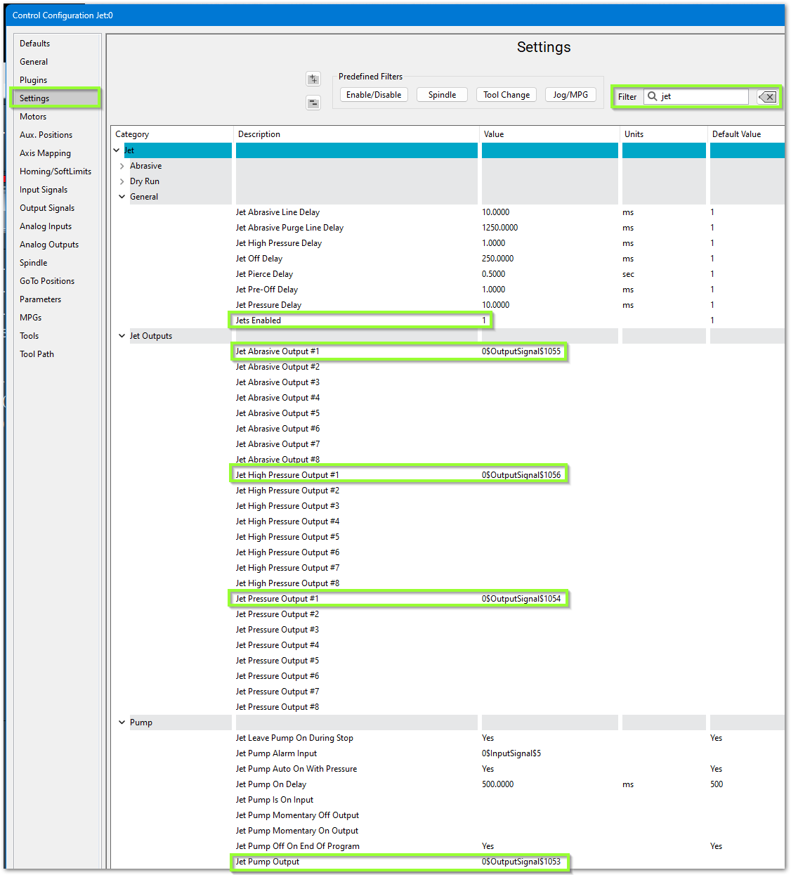
- In the upper right corner, filter the settings for jet
- Set Jets Enabled to 1. Even if you have more jets, configure one jet completely to understand the settings, then change this value to the number of jets you have, and configure the remaining jets.
- Configure the software to use your previously mapped signals
- Jet Pump Output #1 maps to Pump or Intensifier ON
- Jet Pressure Output #1 maps to Jet Pressure On
- Jet Abrasive Output #1 maps to Abrasive On
- Jet High Pressure Output #1 maps to High Pressure
Jet Delay Settings
There are default jet delay settings which you may adjust.

Jet Pressure Delay (ms) “JetPressureDelay”- Turns Jet on, then applies delay, then turns on Abrasive.
Jet Pre-Off Delay (ms) “JetPreOffDelay”- Applies delay, then turns Jet off.
Jet Off Delay (ms) “JetOffDelay”- Turns Jet off, then applies delay.
Jet Pierce Delay (sec) ““JetPierceDelay”- Turns Jet on, then applies delay.
Jet High Pressure Delay (ms) “JetHighPressureDelay”- When “High Pressure Toggle” is high, it applies the delay, then turns on Jet and Abrasive. No yellow wait bar appears.
Jet Pump On Delay (ms) “JetPumpAutoOnDelay”- Turns on Pump, applies delay, flashes button until delay is over
Jet Abrasive Line Delay (ms) “JetAbrasiveDelay”- Turns Jet and Abrasive on at the same time. Then applies the delay. Identical to “Jet Abrasive On Delay” and “Jet Pierce Delay”.
Jet Abrasive On Delay (sec) “JetAbrasiveOnDelay”- Turns Jet and Abrasive on at the same time. Then applies the delay. Identical to “Jet Abrasive Line Delay” and “Jet Pierce Delay”.
Jet Abrasive Off Delay (sec) “JetAbrasiveOffDelay”- Turns off Abrasive, applies delay, Turns off Jets. Identical to "Jet Abrasive Purge Line Delay"
Jet Abrasive Purge line Delay (ms) “JetAbrasivePurgeDelay”- Turns off Abrasive, applies delay, Turns off Jets. Identical to “Jet Abrasive Off Delay”.
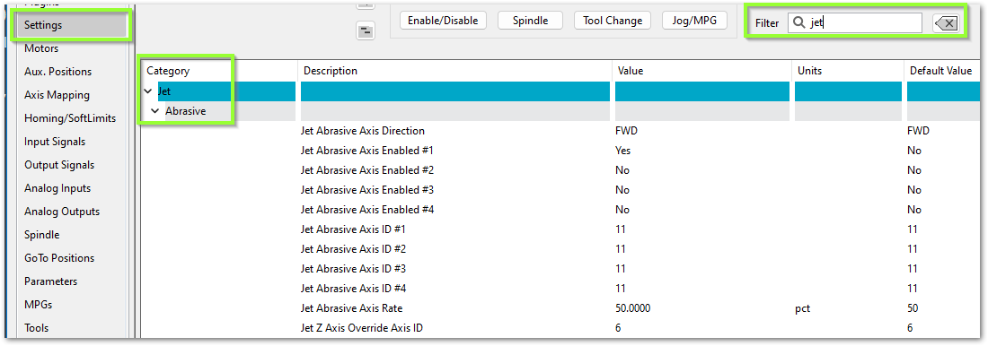
Servo Abrasive Setup
Some waterjets have a servo controlled Abrasive. For that use these settings:
Intensifier Control
Overview
The Mach waterjet control supports intensifier pump systems for high-pressure waterjet cutting. The intensifier control system provides automatic monitoring and safety protection for critical components including check valves, oil temperature, bleed-down systems, and water pressure. The control can manage up to two independent intensifier units with comprehensive monitoring and diagnostic capabilities.
Intensifier Safety Monitoring
The control continuously monitors the intensifier system and will automatically disable the machine or alert the operator when safety conditions are detected. All intensifier monitoring systems integrate with the Global Monitoring System (GMS) to provide real-time alerts and automatic protective actions.
Temperature Monitoring
Check Valve Temperature Alarms
- Each intensifier supports monitoring for two check valves
- When a check valve temperature alarm is triggered, the machine will immediately disable and alert the operator
- This protects the check valves from thermal damage during operation
- Action: Machine disables automatically - Check the cooling system and allow check valves to cool before resuming operation
Oil Temperature Warning
- Provides early notification when intensifier oil temperature is elevated but still within safe operating range
- Allows the operator to take corrective action before reaching critical temperature
- The machine will continue to operate but displays a warning notification
- Only monitors when the jet pump is running (pressure ramping or at full pressure)
- Action: Monitor the oil temperature - Consider reducing duty cycle or checking oil cooling system
Oil Temperature Alarm
- Triggers when oil temperature reaches critical levels
- Machine will immediately disable to prevent damage to the intensifier
- Only monitors when the jet pump is running (pressure ramping or at full pressure)
- Action: Machine disables automatically - Allow oil to cool and inspect cooling system before resuming
Bleed Down Over Temperature Alarm
- Monitors the temperature of the bleed-down valve system
- When temperature exceeds safe limits, the machine disables automatically
- Action: Machine disables automatically - Check bleed-down valve operation and cooling
Oil Level Monitoring
Oil Low Alarm
- Monitors the hydraulic oil level in the intensifier reservoir
- When oil level drops below minimum safe operating level, machine disables immediately
- Action: Machine disables automatically - Check for leaks and refill oil to proper level before resuming
Water Pressure Monitoring
Inlet Water Pressure Low Warning
- Provides early notification when inlet water pressure drops below optimal level
- Machine continues to operate but alerts the operator
- Only monitors when the jet pump is running (pressure ramping or at full pressure)
- Action: Check water supply pressure and flow - Address before pressure drops further
Inlet Water Pressure Low Alarm
- Triggers when inlet water pressure is insufficient for safe intensifier operation
- Machine will immediately disable to prevent damage
- Only monitors when the jet pump is running (pressure ramping or at full pressure)
- Action: Machine disables automatically - Verify water supply is adequate and pressure sensor is functioning
Stroke Monitoring
Stroke Over Speed Alarm
- Monitors the stroke rate of each intensifier
- Triggers when stroke rate exceeds the configured maximum safe speed
- Prevents damage from excessive cycling speed
- Machine will disable automatically when detected
- Action: Machine disables automatically - Check for pressure control issues or improper settings
Stroke Stall Alarm
- Monitors for insufficient stroke rate indicating stalled operation
- Triggers when stroke rate falls below the configured minimum
- Detects mechanical binding or insufficient pressure
- Machine will disable automatically when detected
- Action: Machine disables automatically - Inspect for mechanical issues or pressure problems
Configuring Intensifier Setting
The intensifier settings can be accessed on the [Service/Maintenance] tab by pressing the [Interface Config] button. Navigate to the Jet/Intensifier section.
Input/Output Configuration
For each intensifier unit, the following inputs and outputs must be mapped:
Intensifier 1 & 2 Shift Control:
- Shift Left Input - Confirms intensifier has shifted to left position
- Shift Left Output - Commands intensifier to shift left
- Shift Right Input - Confirms intensifier has shifted to right position
- Shift Right Output - Commands intensifier to shift right
Temperature Monitoring Inputs:
- Check Valve 1 Temperature Alarm Input - Digital input from check valve 1 temperature switch
- Check Valve 2 Temperature Alarm Input - Digital input from check valve 2 temperature switch
- Oil Temperature Warning Input - Digital input from oil temperature warning sensor
- Oil Temperature Alarm Input - Digital input from oil temperature alarm sensor
- Bleed Down Over Temperature Alarm Input - Digital input from bleed-down temperature sensor
Pressure and Level Monitoring Inputs:
- Inlet Water Pressure Low Warning Input - Digital input from water pressure warning sensor
- Inlet Water Pressure Low Alarm Input - Digital input from water pressure alarm sensor
- Oil Low Alarm Input - Digital input from oil level sensor
Control Outputs:
- Bleed Down Valve Output - Controls the bleed-down valve solenoid
- Boost Pump Output - Controls the boost pump motor
- Water Cooling Output - Controls intensifier cooling system
- Inlet Water Valve Output - Controls inlet water supply valve
Stroke Monitoring:
- Stroke Over Speed Alarm (Intensifier 1 & 2) - Maximum stroke rate threshold before triggering over-speed protection
- Stroke Stall Alarm (Intensifier 1 & 2) - Minimum stroke rate threshold before triggering stall protection
Timing Settings
Debounce Times (seconds):
These settings prevent false alarms from momentary sensor fluctuations.
- Jet Intensifier Oil Temp Warning Debounce - Time the oil temperature warning input must be active before triggering warning (default: 1.0 seconds)
- Jet Intensifier Oil Temp Alarm Debounce - Time the oil temperature alarm input must be active before triggering alarm (default: 1.0 seconds)
- Jet Intensifier Inlet Water Pressure Low Warning Debounce - Time the water pressure warning input must be active before triggering warning (default: 1.0 seconds)
- Jet Intensifier Inlet Water Pressure Low Alarm Debounce - Time the water pressure alarm input must be active before triggering alarm (default: 1.0 seconds)
Startup and Shutdown Delays:
- Jet Intensifier Inlet Water Pressure Delay - When inlet water pressure sensor is not mapped, this delay (in seconds) is applied after opening the inlet water valve to allow pressure to stabilize (default: 2.0 seconds)
- Jet Intensifier Inlet Water Pressure Wait On Input Timeout - When inlet water pressure sensor is mapped, maximum time (in seconds) to wait for good water pressure signal during startup. If timeout is exceeded, an alarm is triggered (default: 10.0 seconds)
- Jet Intensifier Water Cooling Off Delay - Time (in seconds) to keep cooling water running after intensifier shuts down to ensure proper cool-down (default: 60.0 seconds)
Pump Pressure Control
Overview
The Mach waterjet control provides advanced pressure control for the jet pump system. The pressure control system can operate in two modes: open-loop (simple output control) or closed-loop (automatic pressure regulation with feedback). This allows the system to precisely control cutting pressure for optimal cut quality and consistent results.
Pressure Control Modes
Open-Loop Mode (Basic Pressure Control)
Open-loop mode is enabled when Jet Pump Pressure Control Enable is set to Yes and Jet Pump Pressure Control Closed Loop Enable is set to No.
In this mode, the control sends a command signal directly to the pump's pressure control output based on the operator's pressure setting. The system does not monitor actual pressure - it simply outputs a proportional control signal.
How It Works:
- Operator sets desired pressure set on the screen or (stored in pound variable #9000)
- When pump starts, pressure smoothly ramps up to commanded value over configured ramp time
- Control converts commanded pressure to analog output voltage/current based on scaling settings
- Output signal is sent to pump's pressure control input
- When pump stops, pressure smoothly ramps down over configured ramp time
Advantages:
- Simple configuration - no pressure sensor required
- Predictable and repeatable output
- Smooth pressure transitions with configurable ramp rates
Limitations:
- No feedback - cannot compensate for pressure variations
- Requires manual calibration between commanded pressure and actual output
- Cannot detect if actual pressure deviates from commanded pressure
Closed-Loop Mode (Automatic Pressure Regulation)
Closed-loop mode is enabled when both Jet Pump Pressure Control Enable and Jet Pump Pressure Control Closed Loop Enable are set to Yes, and a pressure sensor input is mapped.
In this mode, the control continuously monitors actual pressure from a sensor and automatically adjusts the output to maintain the desired pressure. This provides precise pressure regulation even when conditions change.
How It Works:
- Operator sets desired pressure on the screen or (stored in pound variable #9000)
- When pump starts, pressure smoothly ramps up to commanded value over configured ramp time
- Control continuously reads actual pressure from analog input sensor
- PI (Proportional-Integral) controller calculates the difference between desired and actual pressure
- Output is automatically adjusted to eliminate pressure error
- Proportional (P) term: Provides immediate response proportional to pressure error
- Integral (I) term: Gradually eliminates steady-state error and compensates for system drift
- System maintains commanded pressure even if pump wear, temperature changes, or load variations occur
- When pump stops, pressure smoothly ramps down over configured ramp time
Advantages:
- Precise pressure control regardless of external conditions
- Automatic compensation for pump wear and system variations
- Consistent cutting results over time
- Monitors actual pressure for quality assurance
Requirements:
- Analog pressure sensor must be installed and mapped
- Sensor scaling must be properly configured
- PI controller gains must be tuned for your specific pump system
Configuring Pressure Control Settings
The pressure control settings can be accessed on the [Service/Maintenance] tab by pressing the [Interface Config] button. Navigate to the Jet/Pressure Control section.
Basic Settings
Jet Pump Pressure Control Enable - Yes/No
- Master enable for pressure control functionality
- When set to Yes: Pressure control is active, output follows commanded pressure with ramping
- When set to No: Pressure control is disabled, output remains at minimum
- Must be enabled for either open-loop or closed-loop operation
Jet Pump Pressure Max - Maximum pressure (psi)
- Maximum pressure the operator can command
- Used for scaling calculations and safety limiting
- Typical value: Maximum rated pressure of your pump system
Jet Pump Pressure Min - Minimum pressure (psi)
- Minimum pressure the operator can command
- Used for scaling calculations
- Output returns to this value when pump is off or during shutdown
Analog Output Settings
Jet Pump Pressure Analog Output - I/O Signal mapping
- Analog output signal that controls the pump's pressure regulator
- Typically a 0-10V or 4-20mA signal to the pump controller
- Must be mapped to a valid analog output
Jet Pump Pressure Output Scale Min - Minimum output value
- The raw output value corresponding to minimum pressure
- For 0-10V systems: typically 0
- For 4-20mA systems: typically 4
Jet Pump Pressure Output Scale Max - Maximum output value
- The raw output value corresponding to maximum pressure
- For 0-10V systems: typically 10
- For 4-20mA systems: typically 20
Ramp Settings
Jet Pump Pressure Ramp Up Time - Ramp up time (seconds)
- Time for pressure to ramp from minimum to maximum when pump starts
- Provides smooth pressure increase to protect pump and plumbing
- Typical range: 5-20 seconds depending on pump size
- Longer ramp times = gentler startup, less mechanical stress
Jet Pump Pressure Ramp Down Time - Ramp down time (seconds)
- Time for pressure to ramp from maximum to minimum when pump stops
- Provides smooth pressure decrease to prevent water hammer
- Typical range: 5-20 seconds depending on pump size
- Longer ramp times = gentler shutdown, less shock to system
Closed-Loop Settings
Jet Pump Pressure Control Closed Loop Enable - Yes/No
- Enables automatic feedback-based pressure regulation
- Requires pressure sensor to be installed and mapped
- When set to Yes: PI controller actively maintains commanded pressure
- When set to No: Open-loop mode - output follows commanded pressure without feedback
Jet Pump Pressure Analog Input - I/O Signal mapping
- Analog input from pressure sensor (transducer)
- Typically a 0-10V or 4-20mA signal from the pressure sensor
- Must be mapped for closed-loop operation
Jet Pump Pressure Input Scale Min - Minimum input value
- The raw input value corresponding to minimum pressure reading
- For 0-10V sensors: typically 0
- For 4-20mA sensors: typically 4
Jet Pump Pressure Input Scale Max - Maximum input value
- The raw input value corresponding to maximum pressure reading
- For 0-10V sensors: typically 10
- For 4-20mA sensors: typically 20
PI Controller Tuning Settings
These settings control the behavior of the closed-loop PI (Proportional-Integral) controller. Proper tuning is essential for stable and responsive pressure control.
Jet Pump Pressure Control Gain KP - Proportional gain
- Controls the immediate response to pressure error
- Higher values = faster response but can cause oscillation
- Lower values = slower response but more stable
- Internal scaling: Displayed value is multiplied by 0.1 internally
- Typical starting value: 10-50 (actual gain 1.0-5.0)
- Tuning tip: Start low and gradually increase until system responds quickly without excessive overshoot
Jet Pump Pressure Control Gain KI - Integral gain
- Controls the accumulation of error over time to eliminate steady-state offset
- Higher values = faster elimination of steady error but can cause instability
- Lower values = slower error correction but more stable
- Internal scaling: Displayed value is multiplied by 0.1 internally
- Typical starting value: 1-10 (actual gain 0.1-1.0)
- Tuning tip: Start very low and increase only if steady-state error persists
Jet Pump Pressure Control Deadband - Deadband (psi)
- Pressure error tolerance zone where PI corrections are not applied
- Prevents unnecessary corrections for minor pressure variations
- Within deadband: Output tracks ramped setpoint with learned integral bias
- Outside deadband: Full PI control actively corrects pressure error
- Typical value: 50-200 psi depending on system and cut quality requirements
- Tuning tip: Larger deadband = more stable but less precise; smaller deadband = more precise but may oscillate
Tuning the Closed-Loop Controller
Proper tuning of the PI controller is essential for optimal performance. Follow this step-by-step procedure:
Initial Setup
- Verify pressure sensor is reading correctly
- Check that sensor input scales properly (min/max values)
- Confirm sensor readings match a calibrated gauge
- Set conservative starting values:
- KP = 10 (actual gain 1.0)
- KI = 1 (actual gain 0.1)
- Deadband = 100 psi
- Set appropriate ramp times (10-15 seconds recommended for initial tuning)
Tuning Procedure
- Start with Proportional Gain (KP)
- Run pump to a moderate pressure (50% of maximum)
- Observe how quickly pressure reaches commanded value
- If response is too slow: Increase KP by 10
- If pressure oscillates or overshoots: Decrease KP by 5
- Repeat until pressure reaches setpoint quickly without excessive overshoot
- Add Integral Gain (KI)
- Monitor for steady-state error (pressure settles slightly above or below target)
- If steady error exists: Gradually increase KI by 1
- If pressure becomes unstable or slow-cycling: Decrease KI
- Goal: Eliminate steady error while maintaining stability
- Adjust Deadband
- Observe pressure stability at setpoint
- If pressure varies unnecessarily: Increase deadband
- If pressure tolerance is too loose: Decrease deadband
- Balance between stability and precision based on cut quality needs
- Test at Multiple Pressures
- Verify controller works well at low, medium, and high pressures
- Fine-tune gains if needed for best overall performance
Troubleshooting Controller Issues
| Symptom | Possible Cause | Solution |
| Pressure oscillates continuously | KP too high, KI too high | Reduce KP first, then reduce KI if needed |
| Slow response to pressure changes | KP too low | Increase KP gradually |
| Pressure settles above/below target | KI too low or zero | Increase KI gradually |
| Pressure hunts or cycles slowly | KI too high | Reduce KI |
| Excessive overshoot on startup | Ramp time too short, KP too high | Increase ramp time, reduce KP |
| Pressure varies unnecessarily | Deadband too small | Increase deadband |
| Pressure doesn't match commanded | Sensor scaling incorrect, output scaling incorrect | Verify input and output scale settings |
| No pressure control response | Closed-loop not enabled, sensor not mapped | Enable closed-loop, verify sensor mapping |
Notes
- The PI controller only operates when the pump motor is up to speed (after initial startup delays)
- Gains are internally scaled by 0.1 to keep displayed values in a reasonable range
- The integral term is clamped to prevent windup and includes anti-windup protection
- Controller state resets when pump shuts down to ensure clean startup on next cycle
- For best results, tune the controller at typical operating pressures for your application
- If you change pump systems or components, re-tune the controller for optimal performance
Alarm Setup
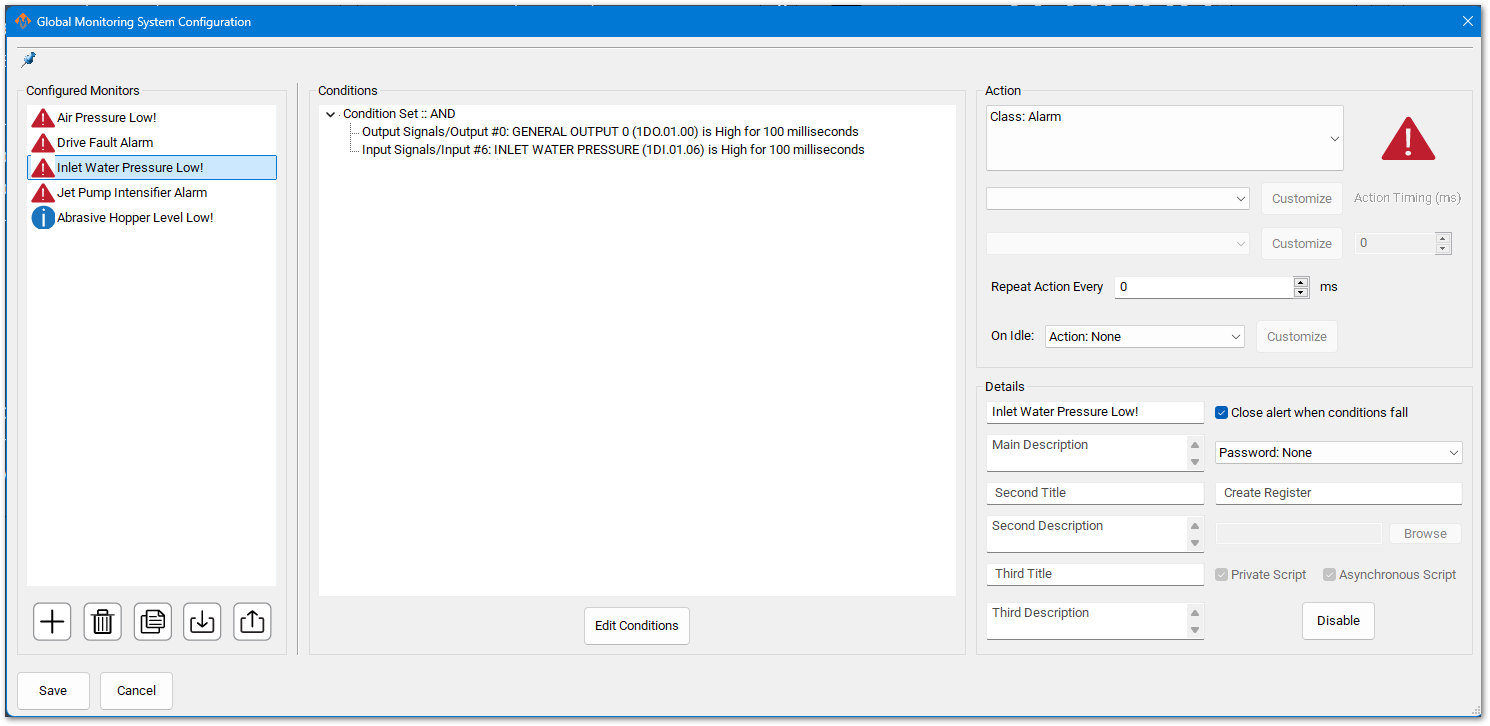
Pull down Configure -> Plugins -> Global Monitoring System (GMS)
You may have inputs for Low Inlet Water Pressure. If so, confirm or update the input signal to match what you have configured on your system. If there is not a GMS monitor for low inlet water pressure, configure a GMS to monitor your signal using the pattern below. See the full MachPro Global Monitoring System documentation if you have not worked with it before.
Next Steps
Move forward to the MachPro Waterjet Operating Manual or back to the MachPro 26 CNC Software Roadmap
| http://www.mach-labs.com | MachLabs Documentation | support@mach-labs.com |
The MachLabs Team
14518 County Road 7240, Newburg, MO 65550
support@mach-labs.com