
MachPro Mill/Router Operating Manual

Introduction
Overview
This manual gives an overview for the basic operation of the MachPro Mill and Router software. The screen is shown below, followed by a brief summary of the different features of the screen. The numbers shown in the screenshot refers to a brief description below the image.
Control Startup
To open the control software, double-click on the profile icon on the desktop.

Gcode Tab

Toolpath Screen
Below are the controls to manipulate the tool path screen:
- Zoom – Right click with the mouse and move mouse up/down or using the scroll wheel on the mouse
- Rotate – Left click with the mouse and rotate the part by moving the mouse
- Pan – Press and hold [Ctrl] on the keyboard and left click with the mouse, then pan by moving the mouse (one-hand control option is to use left and right mouse click and move the mouse. No [Ctrl] press needed)
- Tool Path
- Regen ToolPath - Refresh the toolpath of the gcode
- View Top - Top view of the part
- View ISO - Side view of the part
- File
- Recent - Load a recently loaded gcode program
- Load - Load a program from the computer or flash drive
- Edit - Edit the code that is loaded into the software
- Close - Close the gcode that is currently loaded in the software
- Control
- Cycle Start - Starts the gcode from from the beginning of the part
- Feed Hold - Pauses the gcode program and keeps the spindle running
- Cycle Stop - Stops the gcode program from running
- Reset - Resets the alarm and also enables the machine
- Disable - Disables the control for software configuration changes
- Status
- Status - Displays any current messages (Home All Pressed, Cycle Start Pressed, etc.)
- State - Displays the current state of the machine (Run, Feedhold, etc)
- Cycle Time - Displays how long the gcode has been running
- Date - Date and time of the timezone of the control
- DROs (Axis Digital Readouts)
- MDI - Opens up a window that allows for gcode commands
- Viewing Part - Shows the part coordinates or machine coordinates of the machine
- Active Modals
- Active Offset - Shows the current active fixture offset (G54, G55, etc)
- Tool Display
- T - The current tool number selected
- Next Tool - The next tool that the gcode will need
- Diameter - Diameter of the tool
- Length - Length of the tool
- Feedrate Display
- F - The current feedrate commanded
- Feed OV - The current Feedrate Override utilizing the Feedrate Override knob on the operating panel (0-200%)
- Rapid OV - The current Rapid Override utilizing the Rapid Override knob on the operating panel (0-200%)
- Spindle Display
- S - The current spindle speed
- TSpeed - The current spindle speed feedback
- FWD - Turns on if the spindle is moving Forward, yellow initially and green when commanded RPM is reached
- REV - Turns on if the spindle is moving in Reverse, yellow initially and green when commanded RPM is reached
- Spindle OV - The current spindle override utilizing the spindle override (0-200%)
- Spindle Load - The current spindle load utilizing the spindle speed feedback
- Range - Displays the current spindle range (spindle pulley)
- Advanced
- Single Block - If active the software will go line by line through the gcode when you press the cycle start button
- Block Delete - Deletes the block of gcode that is selected with / or /0-9 at the beginning of the line. Filter for "block" in the MachPro settings to turn on the /0-9 levels option.
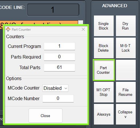
- Part Counter - Displays the number of parts that the machine has produced
- M1 OPT Stop - If active the software will stop at any M1 commands in the gcode program and waits for cycle start
- Alexsys - Opens up the conversational assistant Alexsys in another window
- Dry Run - If active the software will ignore all mist or flood commands
- M-S-T Lock - If active the software will ignore all Macro codes, Spindle codes and Tool commands
- Collapse v - If selected this will minimize the Advanced buttons
- Dashboard
deprecated
see https://support.machmotion.com/books/cnc-software/page/machpro-widgets-dashboard-commands-and-function-buttons
Dashboards
The MachPro controls have three dashboard to customize the interface to meet your needs.
The operator panel has function buttons that can be assigned operations.
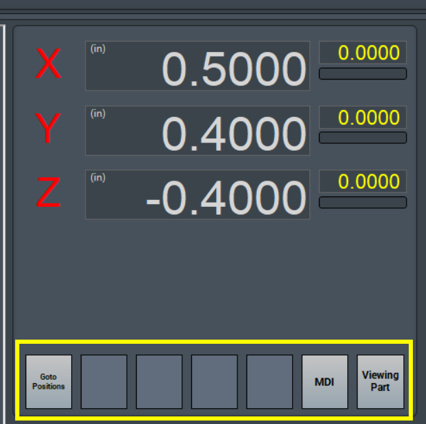
There are two dashboards where you can place widgets. One dashboard is on the far right of the control and is available from all tabs.
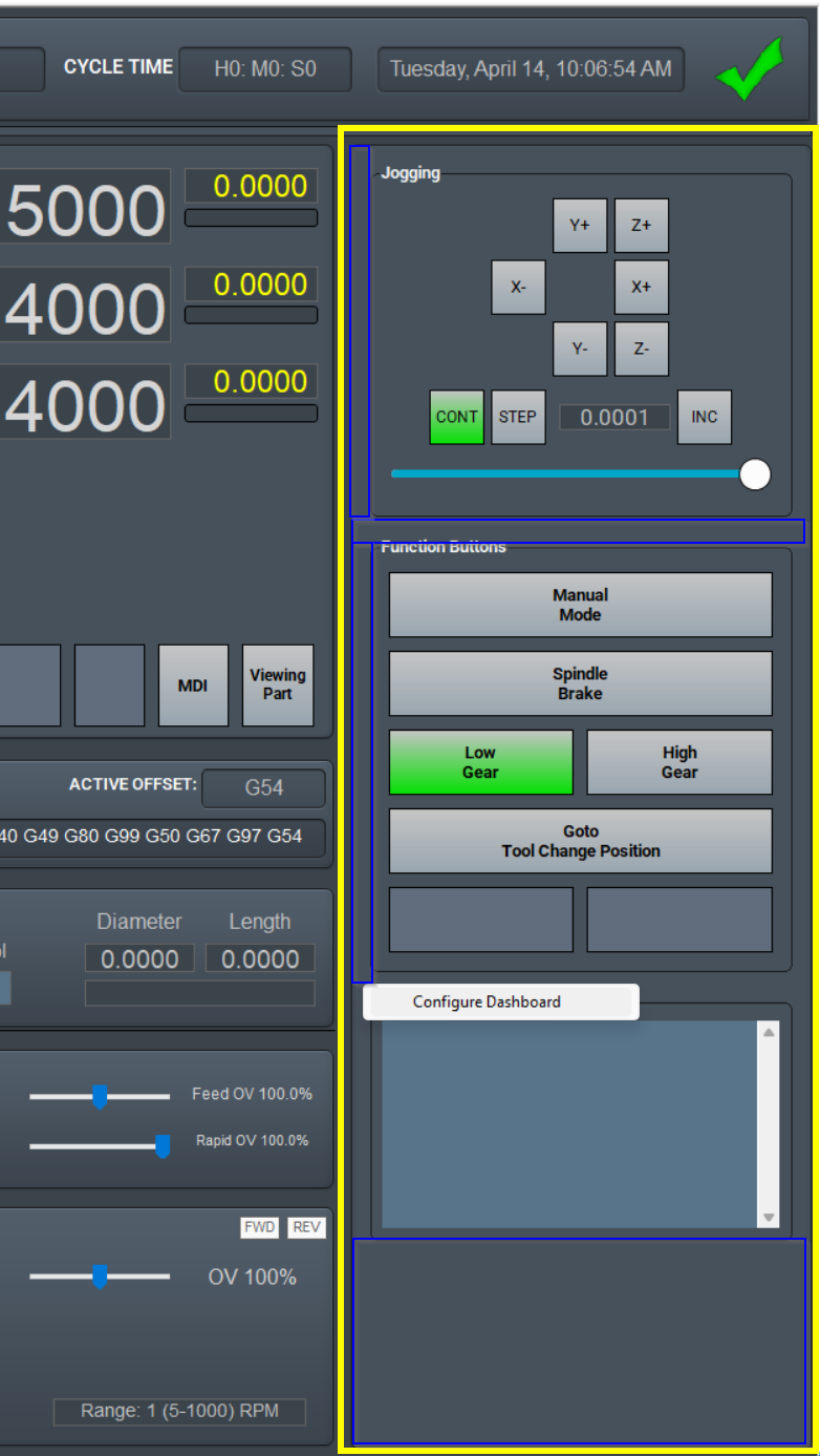
Right click on the unused dashboard space at the bottom, or on the spaces between and around the existing widgets to configure the dashboard.
The third dashboard available to customize is on the service page.
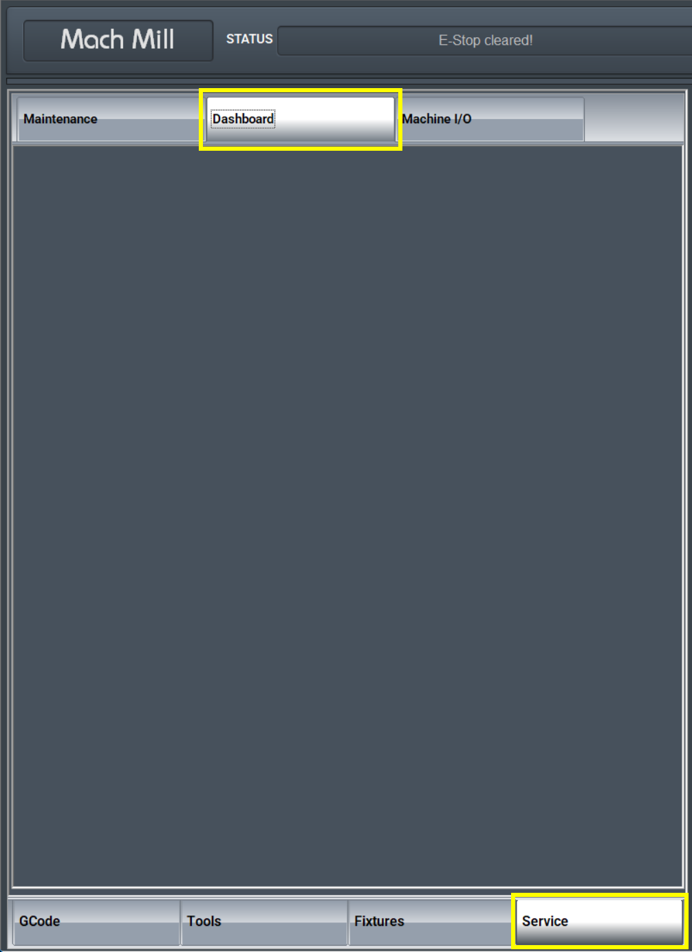
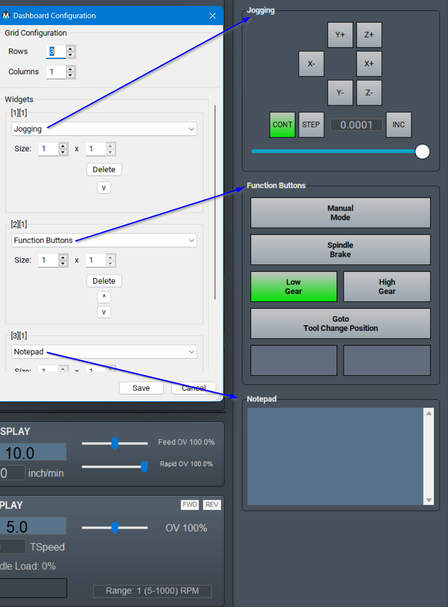
Dashboards can be configured by right-clicking on them to access their menu. The user can choose how many and which widgets to show on the dashboard, as well as their layout. There is a wide variety of widgets to select from, and some widgets have additional options by right-clicking them for the 'Configure Widget' menu.
Widgets are single-task tools designed to be easy to understand and use.
There is a special type of widget - the Function Buttons - which provide customizable tools for advanced users.
Widgets
Widgets are small components that can be added to the dashboards to show data like the last probe position or to add buttons for controlling a chip conveyor. To see the list of available widgets right-click on the edge of a dashboard and click Configure Dashboard.

|
|
|

Many widgets have additional options to configure the way they look or which variables are shown in the widget. So see a list of options right-click inside the widget and select from the menu. The menu is context sensitive and some widgets have additional options, but these three options are always available.
|
Right click directly on an entry. |
Use compact display or specify height of the rows. The default is 22.
Compact vs normal display
|
Select Get Info about the entry you right clicked
|


If "Set Variable Format String" is an option, right-click on the row you want to change and select "Set Variable Format String." Then enter a string format with the following syntax: %.Xf (where the X represents how many decimal places. For example, if you only want 1 decimal place, enter %.1f. This will display a value 170.2353 as 170.2. You have to re-enter the value on the screen for it to display with the new format. Search for external documentation on operator (c-style string formatting) syntax for a complete list of options.
Many of the widgets allow you to add lists to be displayed: parameters, signals, variables, etc. If your options are displayed in a list, then you have several ways to select multiple values.
- You can add an individual item by selecting it, clicking the Add button at the bottom, and then the Close button.
- You can add a contiguous series of items. Select the first item, hold down the shift key on the keyboard and select the last item in the series. Click the Add button.
- You can repeat this action for other series of item, and click Add after each series is selected.
- You can add separate item. Select the first item. Hold down the control key on the keyboard and select each individual item that you want to add to the widget. Click the Add button.
- When you have finished adding all of the items, click the close button.
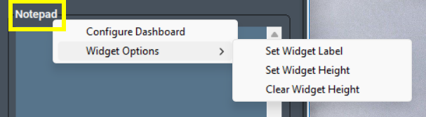
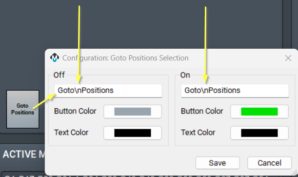
Set Widget Label allows you to rename that item to match usage on this system. Your system will be productive more quickly if you carry over the existing machine labeling to this MachMotion control interface.
Insert a new line code (\n) to break the button label into two lines. Do not add spaces before or after the \n.
All available widgets
All Inputs and All Outputs (Digital)
These are two separate widgets, one for digital inputs and one for digital outputs. They have the same function. They are useful for troubleshooting during installation, and it will display all the inputs or outputs (including ones not enabled or used) in a scroll-able window. Alternately, to just see particular I/O information, use these widgets:
- Analog Input and Output Signals (next entry down)
- Enabled Inputs and Outputs are at the hardware level
- Signals are at the software level and are mapped to particular hardware inputs and outputs
- I/O is a select-able list of both physical I/O and other system information.
|
If you add a description to an input in the Controls Inputs tab, that description will be used here.
Note the scrollbar on the right side. All inputs are visible when you scroll. |
If you right click and select Run Test Sequence, you will see this popup. There are a large number of inputs and running the sequence 10 times will take some time.
|


Analog Input and Output Signals
These are two separate widgets and each allows you to add specific analog input and output signals to your dashboard.
|
To add Analog signals, right click in the widget and select Add Variables.
|
Right click in the widget or directly on one of the signals.
|


Approach Distances
All axes will use this value when doing a probe move for both edges and corners. It is the maximum distance the probe will move while searching for material. If the probe is not activated before this distance is consumed, then an error will occur and the operation will be stopped.
|
|
The Approach Distances widget is incorporated in the Fixtures Tab, and is best used there. |

Axis Compensation
|
|
This is used on grinders to adjust for the grind wheel size changing during dressing or grind cycles. Grinder controls will have these functions configured in their profile, and you will not normally need to add this widget. Refer to the appropriate manual for your type of grinder, and search for compensation. |

Calculator
|
|
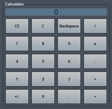
This is a simple calculator that is useful if you often need one while working on the control. There are no special features to configure here. If you need a calculator with more advanced features, the Windows calculator is available. |
Current Fixture Offsets
This displays the current offset of each axis from the machine zero location on that axis. It is the same as the opening the Fixtures Offsets table on the Fixtures tab. This is a display widget. If you want to change these values, open the Fixture Offsets table on the fixtures tab.
|
|
|


Cylindrical Grinder Part Offsets
This is used for Cylindrical grinders. The part offset table (Part Correction Offset) which, when multiple features are being ground on the part, can be used in conjunction with an "E" variable in the program to allow adjustments to each feature individually.

DRO Measure
|
|
This provides a digital "tape measure" that can measure axis movement, and be reset at will. It does not change any operating values or parameters. |

Dual Table
|
|
This widget is used on routers with two tables. Setup and use is documented in the 2000 Series Dual Table article. |

Enabled Inputs and Outputs
|
|
These widgets will show only the inputs or outputs that been enabled. Right clicking on the display will bring up a menu. If you click on a particular input or output, you can get information about that entry. |

Feedback
|
|
This provides an on-screen indicator when any of the axes are moving. You select the axes that you want to monitor. |
|
|
Right click on the border space around the buttons and select Configure Widget to access the display options.
The Grid Configuration, at the top, determines how many rows and columns of axis indicators you will have. |


File Travel Limits
|
|
This displays the extents of movement you will have on each axis for the file that is loaded. Using this along with the yellow soft limit display on the tool path will help you identify fixture problems before you run a file. |

G30 Coordinates
|
|
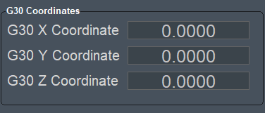
This is similar to the G28 command. G28 ends at machine zero while G30 allows you to specify different end coordinates than machine zero. |
G54 - G59 fixture Offsets
|
This widget displays the current values of your offsets in individual windows for each offset. You may add a widget for each set of offsets that you want to monitor. If you want to change these values, open the Fixture Offsets table on the fixtures tab. If you only need a single widget that dynamically updates to show the current offsets, use the Current Fixture Offsets (above). The Fixtures Tab on the control also provides easy access to the most used fixture features. |
|

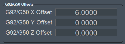
G92/G50 Offsets
Most operators will use G54–G59 fixture offsets or GOTO positions instead of G92 and G50/G52, which were used before fixture offsets existed. Try these features first. You may also use the Head Shift Offset and Work Shift Offset widgets to make adjustments directly on the screen - without any G-Code changes. The Fixtures Tab on the control also provides easy access to the most used fixture features.
There are cases where G92 and G52 are very useful, and for that you need to refer to the full documentation links above.
|
The widget will display any offsets created with G92 or G52 in your G-Code.
|
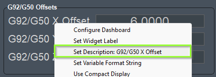
You may also change the labels of the offsets to match your naming convention.
|
Head Shift and Work Shift Offsets
Head Shift and Work Shift offsets are very similar.
- Head shift is used for permanent offsets related to multiple heads - such as a router with a standard spindle, and a drill bank, or an engraving laser. You need to shift your your cut path to use the other tool while maintaining the same fixture coordinates.
- Work shifts are used for temporary changes. Your stock may have a defect and you need to shift your fixture coordinates by 0.005 inches for this piece. This widget provides an easy way to make those kind of temporary adjustments quickly, without changing your existing fixture offsets. When you are done with this piece you can reset the work offsets to 0.0000 and use unmodified fixture offsets.
|
|
|
|
|
|
|
|
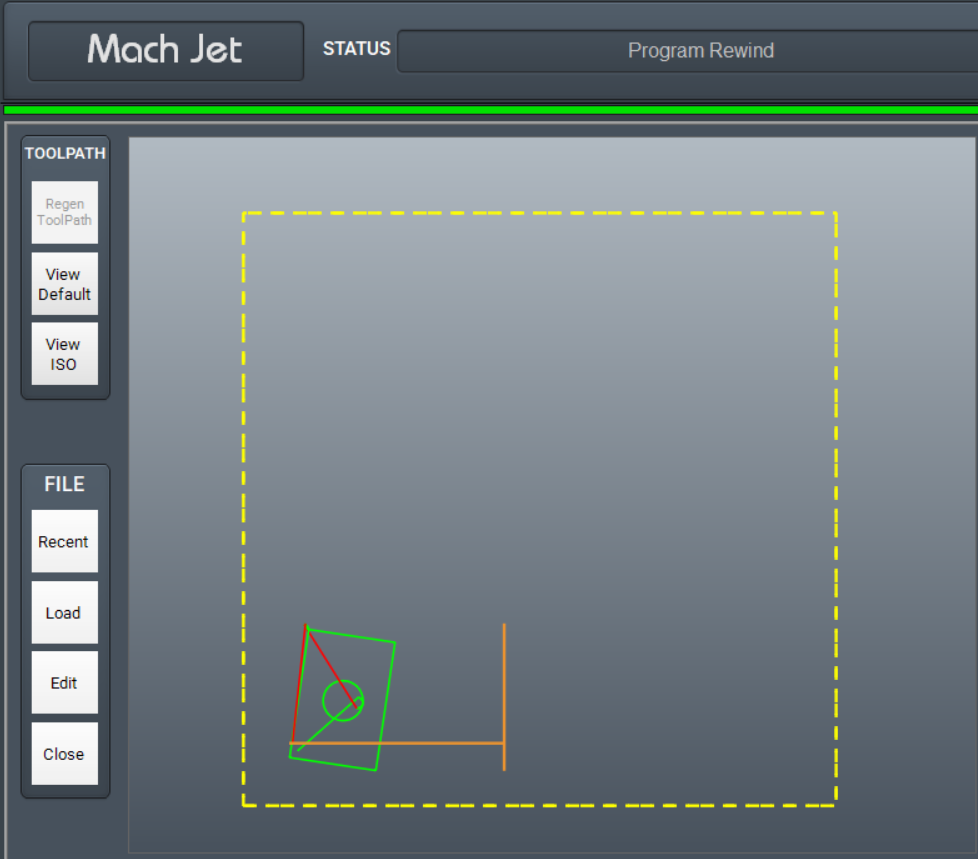
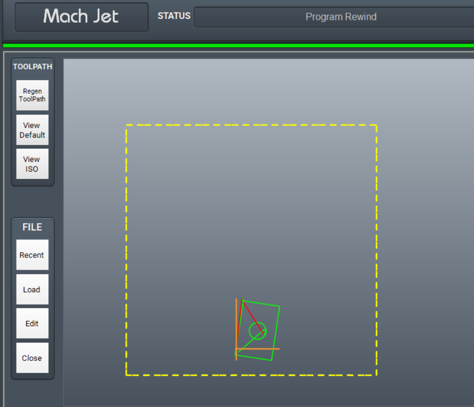
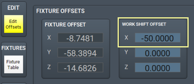
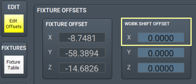
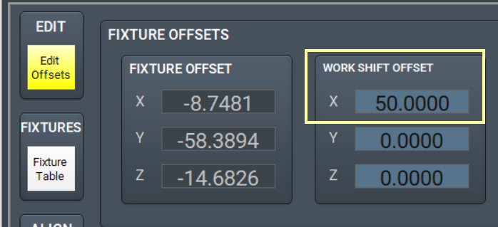
The values entered in the on-screen widget update the fixture table for the head or work shift, but they do not change your current fixture offsets (G54, G55, etc). You change the head shift values in the widget, or directly in the Fixture Offsets Table.
|
|
|


The head and work shift values will reset to zero when you restart the software. If you want to set permanent values for the shifts, you can change that option in the MachMotion Plugin. Your options are:
- Reset to Zero
- Restore the last value you entered
- Restore a permanent value
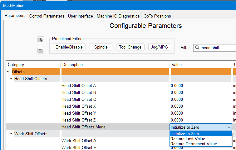
Head and work shift values will not change the standard G54-G59 work offsets, but they do stack on top of those values. You can also have both head shift and work shift values in effect at the same time. The head and work shift values will apply to your current work offsets.
I/O
This is used for diagnostics during system setup, and shows the electrical status of the input and output ports on the main control panel, and diagnostic information about multiple other aspects of the system. See Signals below.
These examples show how the I/O indicators change when the Goto and MDI features are used.
|
|
|
|


|
|
|
|
||
|
|
|
|
||
|
|
|
|


IVIS
This is the interface for a software tool used on some grinders. If your system uses IVIS, we will configure this widget for you.
Job File
This widget is used in custom profiles. Please contact MachMotion for configuration.
Jogging
This widget provides both on-screen and keyboard jogging. There are different on-screen axis button configurations to match your system.
|
|
|
|
|
|
|
Lite is used to select the axis on computers that have physical + and - jog buttons on the panel. |
|

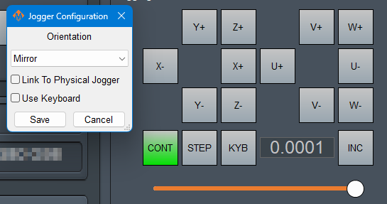


- CONT is continuous movement as long as you press the relevant axis button.
- STEP moves the axis by one increment with each press of the axis button.
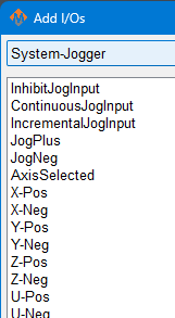
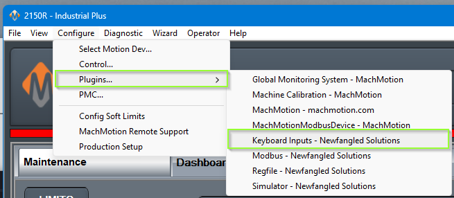
- KYB uses keyboard mappings to control different aspects of the jogging function. Select the functions you want to use in the Jogger Configuration window, then map the key combinations in the Keyboard Inputs plugin.
- INC cycles through the jogging distance increments: 0.0001, 0.001, 0.01, 0.1, 1.0
The Jogger Configuration option to link to the physical jogger, allows you to keep the feedrate value synced with other physical pendants.
This is the feedrate slider

|
Opening the Keyboard Plugin to map keys
|
|

Last Commanded Coordinates

This reports the last position that each axis has been commanded, either by the G-Code file or by MDI.
G0 X1 Y1 Z1
G0 X2 Y2
These G-Codes above resulted in this display. If an axis is not commanded for multiple blocks of code, it will retain the last commanded coordinate.
Mach Parameters
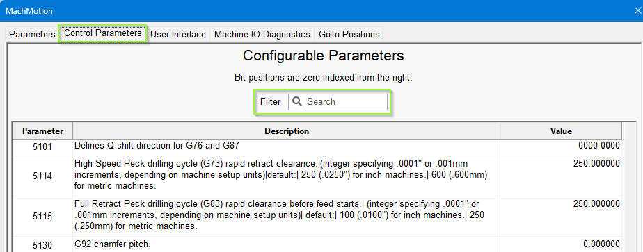
These are the values stored in profile\parameters.ini and are best accessed in the MachMotion Plugin. Pull down the Configure menu | Plugins -> MachMotion parameters. Normally you will not need to monitor or change these values. This widget is primarily used for system customization.
|
|
|


Right-click in the widget to bring up the menu. This menu is specific to #5130 because I right-clicked that entry.
Machine Coordinates
These are the distances from the machine zero on each axis. You can toggle the DRO to show View Machine, and you can use this widget to display machine values at all times. See also Part Coordinates.
|
|
|


Notepad
This is a simple notepad that retains the text even when the control is fully power cycled. Right-clicking will display the options.

Original Offsets
Please refer to, and use, the Current Fixture Offset widget
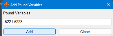
Pound Variables
The system variables, or pound variables (# variables) are documented in the Macro B Reference Guide in the System Variables section. They are shared memory between G-Code files, and M-Codes and plugins.
|
From the Macro B section 3.6 System Variables
|
Setting the widget values
|


Part Counters
This widget is incorporated into the standard interface, on the GCode tab, and it is best used there.
|
|
|

Part Counters (internal documentation)
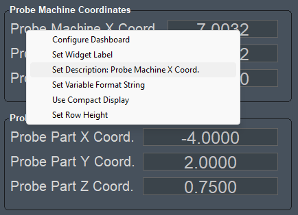
Probe Machine Coordinates and Part Coordinates
|
|
|

Registers
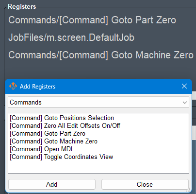
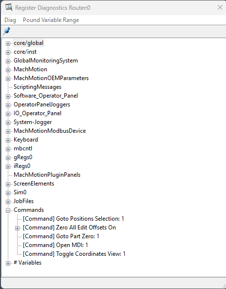
Registers are documented in 4 Registers as part of the core Mach documentation. This widget allows you to display particular registers and their values. You can also browse the entire tree from the main menu. Pull down Diagnostic | Regfile
|
|
|
Scheduler
This widget is used to customize system operation when a customer's work flow requires it. If you need this functionality, please contact MachMotion support and request a quote for custom configuration.
|
|
|


Opening the Scheduler will open a new window with the Schedule Editor. The Load button will open a file browser to select the job files you want to schedule. Once the jobs are listed, you can reorder them, and change the quantity of times to run a particular job.
Signals
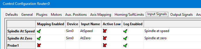
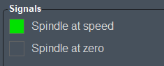
Also see I/O and the mapping documentation for your motion controller. The signals are mapped to particular input and output ports. In this example, the underlying I/O ports are connected, and the signals have been mapped to report I/O status to the system.
|
|
|
|

Subspindle Control
|
This widget is used to set the speed and start the spindle. Configuration details and examples are located in these bookstack articles:
|
|

Tool Wear Offsets
Please enter your tool wear offsets in the Tool Table, or using G10: Fixture and Tool Offset Setting. Refer to the Cutter Compensation portion of the Mach4 G-Code and M-Code Reference for the concepts in cutter compensation.
|
|
|


Software Function Buttons
One particular widget is the 'Function Buttons' widget. It is configurable in a similar way to the overall dashboard, but instead of selecting widgets, the user can select Commands to run on press and release. The user can also set the labels and colors of the button to suit them.


Run MDI and LUA commands
Aside from running Commands, function buttons can be used to run MDI or LUA commands. This is accessible through the right-click menu. Those menu options will only be available if the button does not have a Command set for it already.
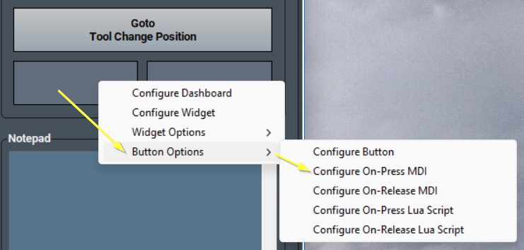
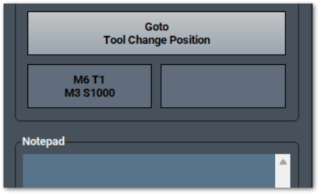
For example, to run this command, enter it exactly as you would type it in a normal MDI window
M6 T1
M3 S1000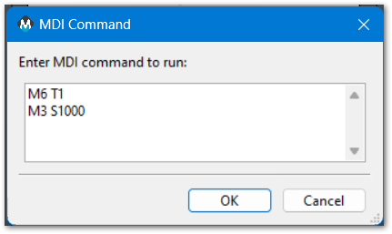
Button press, release, toggle
Usually we only configure the button press, but we can also configure the button release function. Functions that toggle have a similar effect to the press and release functions.

Software Function Button Commands and Descriptions
| Command | Description |
| Block Delete Toggle | When enabled, skips G-code lines beginning with a forward slash (/) during program execution. |
| Clear Scheduler 0 | Clears the pending file queue in the Scheduler for instance 0 on a multi‑instance system. |
| Clear Tool Change State | Resets any in‑progress tool change state back to idle, clearing interlocks or prompts. |
| Close CNC Software | Closes and exits the MachMotion CNC software environment safely. |
| Close GCode | Closes the currently loaded G‑code file without quitting the control software. |
| Compile Scripts | Recompiles .mcs scripts after Mach core configuration changes, ensuring updated logic is active. |
| Convert Screen To Multi Instance | Converts the current screen/profile to support multiple Mach instances on one PC. |
| Cut Recovery | Resumes a program after interruption, re‑establishing position and conditions for safe continuation. |
| Cutter Compensation Type A Toggle | Toggles cutter compensation Type A mode as defined in cutter comp documentation. |
| Cutter Compensation Type B Toggle | Toggles cutter compensation Type B mode as defined in cutter comp documentation. |
| Cutter Compensation Type C Toggle | Toggles cutter compensation Type C mode as defined in cutter comp documentation. |
| Cycle Start | Starts execution of the loaded program; same function as the panel Cycle Start. |
| Cycle Start 0 | Starts execution of the loaded program for instance 0 in a multi‑instance setup. |
| Cycle Stop | Stops the running program or commanded motion; same as the panel Cycle Stop. |
| Cycle Stop 0 | Stops the running program or motion on instance 0 only. |
| DeReference All | Clears referenced (homed) status for all axes on the active instance. |
| DeReference All Instances | Clears referenced (homed) status for all axes across all instances. |
| DeReference X | Clears referenced (homed) status for the X axis. |
| DeReference Y | Clears referenced (homed) status for the Y axis. |
| DeReference Z | Clears referenced (homed) status for the Z axis. |
| Disable | Disables machine motion drives/interlocks system‑wide; machine cannot move. |
| Dry Run To Line | Processes G‑code without coolants to a selected line, helpful for verification. |
| Dry Run Toggle | Toggles dry‑run mode to process code without spindle, mist, or flood outputs. |
| Edit GCode | Opens the loaded G‑code in the editor for quick changes. |
| Edit Offsets Off | Locks offsets to prevent editing in the offsets page. |
| Edit Offsets On | Unlocks offsets, allowing editing of fixture and tool offsets. |
| Edit Offsets Toggle | Toggles between locked and unlocked offset editing states. |
| Edit Scheduler 0 | Opens the Scheduler editor for instance 0 in a multi‑instance system. |
| Enable | Enables machine motion, allowing jogging and program execution. |
| Enable Reset | Enables and arms the Reset system to clear faults and rewind modals. |
| Enable Reset 0 | Arms the Reset system only for instance 0. |
| Enable Scheduler 0 | Enables the Scheduler service for instance 0 so queued jobs can run. |
| Enable Toggle | Toggles machine enable/disable state. |
| Enable X Axis Toggle | Toggles enable state of the X axis servo/drive. |
| Enable Y Axis Toggle | Toggles enable state of the Y axis servo/drive. |
| Enable Z Axis Toggle | Toggles enable state of the Z axis servo/drive. |
| Feed Hold | Pauses program motion and enters hold; can resume with Cycle Start. |
| Feed Hold 0 | Pauses motion for instance 0 only; resume with Cycle Start 0. |
| Feed Hold Retract | Retracts along a safe vector while entering feed hold to clear the part. |
| Feed Hold Retract 0 | Retracts and holds on instance 0 only. |
| Feedrate Override Decrement | Decreases commanded feedrate override in preset steps. |
| Feedrate Override Increment | Increases commanded feedrate override in preset steps. |
| Feedrate Override Reset | Resets feedrate override to 100% (nominal programmed feed). |
| File Resume | Resumes execution of a previously paused or interrupted file. |
| Find Tool Changes | Scans the loaded G‑code and highlights M6 tool change locations. |
| Flood Toggle | Turns flood coolant on or off. |
| GCAdapter Adapt Folder | Processes all files in a folder with the G‑code Adapter per configured rules. |
| GCAdapter Adapt Folder Showing Toolpaths | Adapts a folder and displays resulting toolpaths for review. |
| GCAdapter Adapt GCode | Runs G‑code Adapter on the current file to apply post/cleanup rules. |
| GCAdapter Settings | Opens the G‑code Adapter settings dialog for configuration. |
| GCode CNTL 1 MST Toggle | Toggles M/S/T lock behavior for GCode Control 1 (mist, spindle, tool). |
| GCode File Repeat Off | Disables automatic repeating of the loaded G‑code file. |
| GCode File Repeat On | Enables automatic repeating of the loaded G‑code file. |
| GCode File Repeat Toggle | Toggles the file repeat setting for the loaded program. |
| GCode Shortcut1 | Executes user‑assigned shortcut action 1 for G‑code operations. |
| GCode Shortcut2 | Executes user‑assigned shortcut action 2 for G‑code operations. |
| GCode Shortcut3 | Executes user‑assigned shortcut action 3 for G‑code operations. |
| Goto Machine Zero | Moves to machine coordinate zero (G53 origin) using a safe move. |
| Goto Part Zero | Moves to current work offset origin (e.g., G54 X0 Y0 Z0) safely. |
| Goto Positions Selection | Moves to a position selected from predefined positions list. |
| Goto Tool Change | Moves to the defined tool change position for manual or automatic changes. |
| Home All | Homes all axes on the active instance. |
| Home All 0 | Homes all axes on instance 0. |
| Home All Dereferenced Axes | Homes only axes currently not referenced (not homed). |
| Home All Selected Instance | Homes all axes on the currently selected instance in multi‑instance systems. |
| Home X | Homes the X axis using its home switch routine. |
| Home Y | Homes the Y axis using its home switch routine. |
| Home Z | Homes the Z axis using its home switch routine. |
| Inhibit Jogging When Not Homed Toggle | Prevents jogging until the machine has been homed; safety interlock. |
| Inhibit X Jogging Toggle | Enables or disables jogging on the X axis. |
| Inhibit Y Jogging Toggle | Enables or disables jogging on the Y axis. |
| Inhibit Z Jogging Toggle | Enables or disables jogging on the Z axis. |
| Interrupt | Triggers an immediate program interrupt for safe attention or intervention. |
| Jog Tool Magazine To Next Pocket | Jog the tool magazine to the next pocket position. |
| Jog Tool Magazine To Next Pocket 2 | Jog tool magazine 2 to its next pocket position. |
| Jog Tool Magazine To Next Pocket 3 | Jog tool magazine 3 to its next pocket position. |
| Jog Tool Magazine To Next Pocket 4 | Jog tool magazine 4 to its next pocket position. |
| Jog Tool Magazine To Previous Pocket | Jog the tool magazine to the previous pocket position. |
| Jog Tool Magazine To Previous Pocket 2 | Jog tool magazine 2 to its previous pocket position. |
| Jog Tool Magazine To Previous Pocket 3 | Jog tool magazine 3 to its previous pocket position. |
| Jog Tool Magazine To Previous Pocket 4 | Jog tool magazine 4 to its previous pocket position. |
| Laser Pointer Toggle | Turns the laser pointer alignment aid on or off. |
| Limit Override Toggle | Temporarily overrides software limits; use with caution. |
| Load GCode | Opens a file dialog to load a G‑code program into memory. |
| Manual Mode Toggle | Switches between automatic run and manual (MDI/jog) control modes. |
| Mist Toggle | Turns mist coolant on or off. |
| MST Lock Toggle | Toggles lock that prevents Macro, Spindle, and Tool actions. |
| Next Pocket | Advance the currently selected tool magazine to the next pocket. |
| Next Tool | Selects the next tool number in the tool table or changer sequence. |
| OP Zone App QR Code | Displays the Operation Zone app QR code for quick access on mobile devices. |
| Open Commands Dialog | Opens a dialog to issue predefined command macros or actions. |
| Open GCode Nesting | Opens the G‑code nesting utility to arrange multiple parts. |
| Open Global Message Config | Opens configuration for global on‑screen messages and alerts. |
| Open Machine Calibration | Opens the machine calibration hub. |
| Open Machine Calibration Automatic Config | Opens automatic calibration configuration for probes, setters, or routines. |
| Open Machine Calibration Manual Config | Opens manual calibration configuration workflows. |
| Open Machine Calibration Screw Mapping | Opens leadscrew mapping/backlash compensation calibration. |
| Open MachMotion Config | Opens the MachMotion plugin configuration utility. |
| Open MachMotion Modbus Config | Opens Modbus configuration for I/O and device mapping. |
| Open MDI | Opens the MDI input to execute single lines of G‑code. |
| Open Setup Wizard | Launches the guided setup wizard for machine configuration. |
| Optional Stop Off | Turns off M1 optional stop handling within programs. |
| Optional Stop On | Turns on M1 optional stop handling within programs. |
| Optional Stop Toggle | Toggles the M1 optional stop behavior. |
| Park Tool | Parks the current tool at a defined safe location. |
| Part Counters | Opens part counter utilities to view and reset production counts. |
| Plate Alignment | Opens plate alignment routine to square and set workpiece orientation. |
| PLC Sequence Diagnostics | Opens PLC diagnostics to monitor and test sequence logic. |
| Power Off | Shuts down control power with normal delays and interlocks. |
| Power Off Immediate | Immediately shuts down control power, bypassing delays; emergency use. |
| Previous Pocket | Move the tool magazine to the previous pocket. |
| Previous Tool | Selects the previous tool number in the tool table or changer sequence. |
| Recent GCode | Opens a list of recently run G‑code files for quick selection. |
| Refresh Enabled Buttons | Refreshes button enable/disable states based on current machine conditions. |
| Regen ToolPath | Regenerates the toolpath display after edits or reloads. |
| Register Tools | Opens tool pocket registration to map tool numbers to tool pockets |
| Remote Support | Starts a remote support session with MachMotion. |
| Reset | Rewinds the G‑code and resets modal states; clears certain faults. |
| Reset 0 | Performs reset/reload actions for instance 0 only. |
| Reset GCode CNTL 1 MST | Resets M/S/T lock state for GCode Control 1 to defaults. |
| Rewind | Rewinds the current program to its beginning. |
| Rewind 0 | Rewinds the current program to the beginning for instance 0. |
| Run Lua Script | Runs a selected Lua script within the control environment. |
| Save Fixture Offsets | Saves current fixture/work offsets to persistent storage. |
| Screen Profiling For 60 Seconds | Runs performance profiling for 60 seconds and records results. |
| Screen Profiling Toggle | Starts or stops screen performance profiling. |
| Search GCode | Opens search to find text or line numbers within the loaded G‑code. |
| Selected Spindle 1 | Selects spindle 1 as the active spindle for commands. |
| Selected Spindle 2 | Selects spindle 2 as the active spindle for commands. |
| Selected Spindle 3 | Selects spindle 3 as the active spindle for commands. |
| Selected Spindle 4 | Selects spindle 4 as the active spindle for commands. |
| Set GCode CNTL 1 MST | Applies M/S/T lock mode for GCode Control 1 per settings. |
| Set Selected Instance 0 | Sets instance 0 as the active target instance. |
| Single Block Off | Disables single‑block mode; program runs continuously. |
| Single Block On | Enables single‑block mode to execute one block per Cycle Start. |
| Single Block Toggle | Toggles single‑block mode on or off. |
| Skip Spindle Warm Up | Skips the spindle warm‑up routine if scheduled. |
| Soft Limits Off | Disables software travel limits for all axes. |
| Soft Limits On | Enables software travel limits for all axes. |
| Soft Limits Toggle | Toggles software travel limits on or off. |
| Spindle Brake Off | Releases the spindle brake. |
| Spindle Brake On | Applies the spindle brake. |
| Spindle Brake Toggle | Toggles spindle brake between on and off states. |
| Spindle Forward | Starts spindle rotating forward (M3 equivalent). |
| Spindle Forward Toggle | Toggles spindle forward state. |
| Spindle Orient | Orients spindle to a programmed angle for tool change or probing. |
| Spindle Orient Toggle | Toggles spindle orient function on or off. |
| Spindle Override Decrement | Decreases spindle speed override in preset steps. |
| Spindle Override Increment | Increases spindle speed override in preset steps. |
| Spindle Override Reset | Resets spindle speed override to 100%. |
| Spindle Range 00 | Selects spindle gear/range 00. |
| Spindle Range 01 | Selects spindle gear/range 01. |
| Spindle Range 02 | Selects spindle gear/range 02. |
| Spindle Range 03 | Selects spindle gear/range 03. |
| Spindle Range 04 | Selects spindle gear/range 04. |
| Spindle Range 05 | Selects spindle gear/range 05. |
| Spindle Range 06 | Selects spindle gear/range 06. |
| Spindle Range 07 | Selects spindle gear/range 07. |
| Spindle Range 08 | Selects spindle gear/range 08. |
| Spindle Range 09 | Selects spindle gear/range 09. |
| Spindle Range 10 | Selects spindle gear/range 10. |
| Spindle Range 11 | Selects spindle gear/range 11. |
| Spindle Range 12 | Selects spindle gear/range 12. |
| Spindle Range 13 | Selects spindle gear/range 13. |
| Spindle Range 14 | Selects spindle gear/range 14. |
| Spindle Range 15 | Selects spindle gear/range 15. |
| Spindle Range 16 | Selects spindle gear/range 16. |
| Spindle Range 17 | Selects spindle gear/range 17. |
| Spindle Range 18 | Selects spindle gear/range 18. |
| Spindle Range 19 | Selects spindle gear/range 19. |
| Spindle Reverse | Starts spindle rotating in reverse (M4 equivalent). |
| Spindle Reverse Toggle | Toggles spindle reverse state. |
| Spindle Speed Variation Toggle | Toggles speed variation function for spindle conditioning or testing. |
| Spindle Stop | Stops the spindle (M5 equivalent). |
| Start Spindle Warm Up | Starts the spindle warm‑up cycle with programmed steps. |
| Step Into Subs | Enables stepping into subroutines during single‑block debugging. |
| Step Into Subs Toggle | Toggles step‑into‑subroutine behavior. |
| Step Over Subs | Steps over subroutines, executing them without entering during debug. |
| Support | Opens MachMotion support resources or contact launcher. |
| Teach Laser Pointer Offsets | Captures laser pointer offset to spindle for alignment/positioning. |
| Teach WorkShift X Offset | Sets current X as workshift offset for the active fixture. |
| Teach WorkShift Y Offset | Sets current Y as workshift offset for the active fixture. |
| Teach WorkShift Z Offset | Sets current Z as workshift offset for the active fixture. |
| Toggle Coordinates View | Toggles displayed coordinates between machine and part views. |
| Tool Group Table | Opens the tool group table for managing grouped tools. |
| Tool Path Large | Switches toolpath panel to large view layout. |
| Tool Path Small | Switches toolpath panel to small view layout. |
| Tool Path View Bottom | Sets toolpath camera to bottom view. |
| Tool Path View ISO | Sets toolpath camera to isometric view. |
| Tool Path View Left | Sets toolpath camera to left view. |
| Tool Path View Right | Sets toolpath camera to right view. |
| Tool Path View Top | Sets toolpath camera to top view. |
| Transform: Array | Creates an array using the G-code part. Provides basic nesting function. |
| Transform: Mirror X | Mirrors toolpath across X axis. |
| Transform: Mirror Y | Mirrors toolpath across Y axis. |
| Transform: Rotate 180 | Rotates toolpath 180 degrees about the origin. |
| Transform: Rotate 90 CCW | Rotates toolpath 90 degrees counter‑clockwise. |
| Transform: Rotate 90 CW | Rotates toolpath 90 degrees clockwise. |
| UPS Power Off | Commands UPS‑coordinated shutdown of control power. |
| Zero All | Zeros all displayed work coordinates for X, Y, and Z. |
| Zero All Edit Offsets On/Off | Zeros all axes and toggles offset editing lock accordingly. |
| Zero X | Zeros X in the active work coordinate system. |
| Zero X Edit Offsets On/Off | Zeros X and toggles offset editing lock accordingly. |
| Zero Y | Zeros Y in the active work coordinate system. |
| Zero Y Edit Offsets On/Off | Zeros Y and toggles offset editing lock accordingly. |
| Zero Z | Zeros Z in the active work coordinate system. |
| Zero Z Edit Offsets On/Off | Zeros Z and toggles offset editing lock accordingly. |
Commands
The system has many packaged functions called commands. These commands can perform a variety of actions, such as turning on the spindle or zeroing an axis. All commands have an action associated with them. Some actions also have a feedback associated with them, such as the 'Spindle Forward' command where the feedback is whether the spindle is currently running forward or not.
Commands and User Commands can be assigned to function buttons on the control, in order to customize the experience.
User Commands
Additionally custom commands, called User Commands, can be configured in the 'Screen Configuration' dialog. This is accessible through the 'Screen Config' button on the Service/Maintenance tab.

To make a new User Command, press the 'Add' button. Each User Command should have a unique name. To edit a User Command, select its name from the list. A searchable list of actions for the command is available in the first box. This selects the general type of action to be done. The second box, labeled 'Options', is also part of the action and must be selected.
The 'Feedback Source' and 'Feedback Target' sections are optional. They are relevant if the User Command will be assigned to a function button. Some User Commands won't have a logical feedback source. A reasonable example is for a command that turns soft limits on and off: the feedback would be if soft limits is on or off. The feedback target offers a way to do a simple forwarding of the user command state if desired.

One option for user commands are User Scripts. These are lua functions that will be executed as the command, to get the feedback state, or to forward to the target. This is a way to create completely custom functionality. They should always be done in the UserGUIModule.UserStartUpScript function. The following is an example of how to create these lua function in the UserGUIModule.
function UserGUIModule.UserStartUpScript()
  local action_func = function()
          local state = w.GetSignalState(mc.OSIG_OUTPUT0)
          w.SetSignalState(mc.OSIG_OUTPUT0, not state)
      end
  w.CreateUserCommandActionOption("Toggle Output #0", action_func)

  local feedback_func = function()
          return w.GetSignalState(mc.OSIG_OUTPUT0)
      end
  w.CreateUserCommandFeedbackOption("Output #0", feedback_func)

  return true, true, w.FunctionCompleted()
end
Hardware Function Buttons
The MachPro operator panels and wireless pendants have a number of function buttons on them, labelled F1, F2, etc. These buttons initially do nothing, but can have commands or user commands mapped to them. This is done through the MachMotion operator panel configuration.
Upon saving and exiting configuration, these commands will be mapped to the function buttons.

On the screen, there are five function buttons underneath the axis DROs. Instructions on how to configure those buttons, as well as how to add more function buttons to the screen, are in the Dashboard section.
| http://www.mach-labs.com | MachLabs Documentation | support@mach-labs.com |
The MachLabs Team
14518 County Road 7240, Newburg, MO 65550
support@mach-labs.com
Tools Tab

- Edit
- Edit Offsets - No offset changes can be made unless this value is yellow. It also displays or hides the zero buttons near the DROs to the right.
- Tools
- Tool Table - View and edit tool table. See the Tool X and Y Offsets below.
- Pockets
- Register Tools - Register and save tools
- Setters
- Tool Setters - Select this to add or remove a tool setter. See Creating a Tool Setter below.
- Park Tool - Park the currently loaded tool and leave the spindle empty
- Jump to Tool Number
- 1,2,3,4 etc. - Tool number (Tool change). Just press the button and the tool will change.
For 7-13 see the [Gcode Tab] above for more details
Open the Tool Table

Open the Tool Table Editor
-
In the tool table window, click Edit → Table Fields.

Add the X and Y Offset Fields
-
Click the Optional Field tab.
-
Find the field name XOffset, select it, and click Move Pri.
-
Do the same for YOffset.
-
Click OK to save.
-
You should now see X and Y offset columns in your tool table.
Set the Master Tool
-
Choose one tool to be your master tool.
Measure and Enter Offsets
- For each other tool, measure the distance from the master tool in both X and Y directions.
-
Enter those distances into the XOffset and YOffset fields for each tool.
Tool Spindle Rotation Options
Open the Tool Table
-
Click View → Tool Tables.
Open the Tool Table Editor
-
Click Edit → Table Fields.

Add a User Field for Spindle Options
-
Click the User Field tab.
-
Click Add.
-
Set up the new field exactly as shown in the example image.
-
Click OK when done.

View and Use the User Field
-
Click View → User Fields.
-
The new user field will now appear for each tool.

Set Rotation for Each Tool
-
For every tool, choose the correct spindle rotation option.
-
Example: For a probe tool, select No Rotation.
-
When you select a tool with “No Rotation,” you cannot turn on the spindle.
-
If you try, you will see an alarm message instead.


| http://www.mach-labs.com | MachLabs Documentation | support@mach-labs.com |
The MachLabs Team
14518 County Road 7240, Newburg, MO 65550
support@mach-labs.com
Fixtures Tab
Manual Setup

- Edit
- Edit Offsets - View and edit fixture offsets, hide and reveal DRO zero buttons to the right
- Fixtures
- Fixtures Table - View and edit fixture table (G54, G55, G56, etc.)
- X/Y Edge Finder Offset
- X+ - Zeros the X + offset
- X- - Zeros the X - offset
- Y+ - Zeros the X+ offset
- Y- - Zeros the Y- offset
- Edge Finder Diameter - This is the diameter of the edge finder used to calculate the new offset based on the zero button pressed above.
- Fixture Offsets
- X, Y, Z, etc. - Shows the currently loaded offsets
- Rotary Axis Tool Path
- X,Y, Z -
For 6-13 see the [Gcode Tab] above for more details
Probe
| MachPro Version | less than 2026.5.13.1 |
Edge and Angle Finding
The Edge Finding tools are available on the Fixtures Tab -> Edge Finding.

Edge Finding Settings
Edges have two options for when the probe makes contact. The work offset can be zeroed at the edge or the position where the edge is found can be reported without zeroing. This selection is made in the 'Settings' group on the edge finding page. The following settings apply to edge finding of either type.
X/Y Reposition Distance: This is the distance used for the X and Y axes to travel in free space during corner findings. It should be a large enough distance for both axes to clear the edge of the corner. These moves will be made as protected moves.
Z Reposition Distance: This is the distance the Z will move in free space during corner findings. It should be greater than your retract distance, in order for the Z axis to reach the side of the material. This move will be made as a protected move.
Approach Distance: All axes will use this value when doing a probe move for both edges and corners. It is the maximum distance the probe will move while searching for material. If the probe is not activated before this distance is consumed, then an error will occur and the operation will be stopped.
Retract Distance: This distance is used after a probe touch to remove the probe from the side of the material. It should be a sufficient distance to deactivate the probe. This distance is also used during the probe double-touch if that feature is activated.

Angle Finding Settings
Angles have two methods of being measured. For small pieces with no movement interference, there are four canned functionalities. These options will probe the side of the part, then move a specified distance along the part, and probe the side again. If the part is large or the user wants more control over measuring the angle, they can enter Jog Mode. Once they activate this mode, they can probe a side of the material, then jog the machine to a new position and probe the side again. This is useful to expedite travel from one end of a part to another.
Angle Measure Options: There are five options for the user to choose from here. This selection will determine how the machine operates during an angle probing operation.
X--: The probe will move in the negative X direction. This means it will be touching the east side of the part.
X++: The probe will move in the positive X direction. This means that it will be touching the west side of the part.
Y--: The probe will move in the negative Y direction. This means it will be touching the north side of the part.
Y++: The probe will move in the positive Y direction. This means it will be touching the south side of the part.
Jog Mode: The probe will move in the direction that the user chooses later.
Reposition Distance: This is the distance that the probe will move between the two probing operations of an angle probe. It can be positive or negative. It is only used when not in Jog Mode. This move will be done in as a protected move at the 'First Touch' feed rate.
Approach Distance: This is the distance that the probe will attempt to move in order to probe the material. If the material is not reached before this distance is consumed, then an error will occur and the operation will stop. This value should be a positive value.
Retract Distance: This distance is used after a probe touch to remove the probe from the side of the material. It should be a sufficient distance to deactivate the probe. This distance is also used during the probe double-touch if that feature is activated.

Probe Configuration Settings
The following options can be set on the 'Settings' page of the wizard and will be applied across both edge finding operations and angle finding operations.
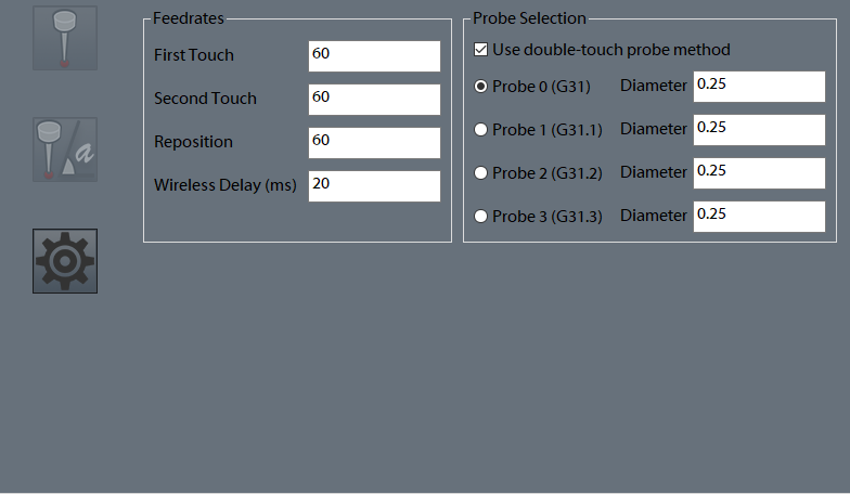
First Touch: This is the first field in the 'Feedrates' section of the settings. This value is the feed rate that the probe will use for the first touch of each probe operation. It is required to be positive.
Second Touch: This is the second field in the 'Feedrates' section of the settings. This value is the feed rate that the probe will use for the second touch of each probe operation, if the double-touch feature is enabled. It is required to be positive. This is typically a slower feed rate for a more accurate reading.
Reposition: This is the third field in the 'Feedrates' section of the settings. This is the distance that the probe will retract from the part after each touch.
Wireless Delay (ms): If the configured probe is wireless, an optional number of milliseconds here can be added as a delay during probe arming, in order to allow the probe to complete the arm sequence before checking for errors.
Double-touch: Check this box to use two probe touches during all probe moves. If this box is unchecked, all probes will use only one touch and will do their touch at the 'First Touch' feed rate.
Probe Diameter: This is the diameter of the probe stylus being used. This must be an accurate number in order to get an accurate fixture offset.
Probe Code Options: The user can specify which probe signal to watch for while running a probe operation. In Mach, G31 corresponds to the “Probe” input signal, G31.1 is the “Probe 1” input signal, G31.2 is the “Probe 2” input signal, and G31.3 is the “Probe 3” input signal. The probe must be wired and mapped correctly to the selected signal for these operations to work.
Status
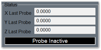
There are two sections to the Status column that appears on all pages other than 'Settings'. The first section shows the last probed position for the X, Y, and Z axes. The positions will be shown in work coordinates, unless the "Machine Coordinates" signal is active, in which case they will be shown in machine coordinates.
The second section is an LED that indicates if the currently selected probe is active or not. If in the settings, the user has G31 selected, then the LED will correspond to the input signal “Probe”. If they have selected G31.1, then the LED will indicated that status of the input signal “Probe 1”. The LED will mark the state of the input signal “Probe 2” if the user has selected G31.2 in the settings, and the LED will correlate with the “Probe 3” input signal if the user selected G31.3.
Functions
There are fourteen functions that the probing wizard can do. There are four operations that find a single edge of the part, four operations for finding a corner of the part, one operation to find the center of a circle, one operation to find material top (Z axis), and four operations to find the angle of a part.
When commanding any probe motions, be sure that your ‘Probe Code Options’ field is set to the correct probe.
Edge Finder

Corner Finder

 The first button, which will zero on the top left corner, will start by moving downwards and locating the top of the part. It will do a full two-touch routine (if enabled) and then zero the Z axis. Next, it will move in the positive Y axis the distance specified in your ‘X/Y Reposition Distance’ field. It is important that the distance is correct in order to properly be clear of the part. After this move, Z will descend by the 'Z Reposition' distance. Once the Z has been lowered, the probe will move in the negative Y direction and probe the top edge of the part. This is the same routine as the corresponding edge finder. After probing Y, the Y axis will be zeroed and the Z will raise up. The Y axis will return back to its starting position over the part. Then X axis will move in the negative X direction the reposition distance so that it will be clear of the part. The Z will again descend the same Z reposition distance. At this point, the X axis will perform a full probe routine in the positive X direction. After probing the X edge and setting the zero, the Z axis will raise up, the both X and Y will move to zero. At the end of the routine, X and Y will be at zero and the Z axis will be at the retract distance away from its zero point.
 The second button, which will zero on the top right corner, will start by moving downwards and locating the top of the part. It will do a full two-touch routine (if enabled) and then zero the Z axis. Next, it will move in the positive Y axis the distance specified in your ‘X/Y Reposition Distance’ field. It is important that the distance is correct in order to properly be clear of the part. After this move, Z will descend the 'Z Reposition' distance. Once the Z has been lowered, the probe will move in the negative Y direction and probe the top edge of the part. This is the same routine as the corresponding edge finder. After probing Y, the Y axis will be zeroed and the Z will raise up. The Y axis will return back to its starting position, over the part. Then X axis will move in the positive X direction the reposition distance so that it will be clear of the part. The Z will again descend the same Z reposition distance. At this point, the X axis will perform a full probe routine in the negative X direction. After probing the X edge and setting the zero, the Z axis will raise up, the both X and Y will move to zero. At the end of the routine, X and Y will be at zero and the Z axis will be at the retract distance away from its zero point.
 The third button, which will zero on the bottom left corner, will start by moving downwards and locating the top of the part. It will do a full two-touch routine (if enabled) and then zero the Z axis. Next, it will move in the negative Y axis the distance specified in your ‘X/Y RepositionDistance’ field. It is important that the distance is correct in order to properly be clear of the part. After this move, Z will descend the 'Z Reposition' distance. Once the Z has been lowered, the probe will move in the positive Y direction and probe the bottom edge of the part. This is the same routine as the corresponding edge finder. After probing Y, the Y axis will be zeroed and the Z will raise up. The Y axis will return back to its starting position, over the part. Then X axis will move in the negative X direction the reposition distance so that it will be clear of the part. The Z will again descend the same Z reposition distance. At this point, the X axis will perform a full probe routine in the positive X direction. After probing the X edge and setting the zero, the Z axis will raise up, the both X and Y will move to zero. At the end of the routine, X and Y will be at zero and the Z axis will be at the retract distance away from its zero point.
 The fourth button, which will zero on the bottom right corner, will start by moving downwards and locating the top of the part. It will do a full two-touch routine (if enabled) and then zero the Z axis. Next, it will move in the negative Y axis the distance specified in your ‘X/Y RepositionDistance’ field. It is important that the distance is correct in order to properly be clear of the part. After this move, Z will descend the 'Z Reposition' distance. Once the Z has been lowered, the probe will move in the positive Y direction and probe the bottom edge of the part. This is the same routine as the corresponding edge finder. After probing Y, the Y axis will be zeroed and the Z will raise up. The Y axis will return back to its starting position, over the part. Then X axis will move in the positive X direction the reposition distance so that it will be clear of the part. The Z will again descend the same Z reposition distance. At this point, the X axis will perform a full probe routine in the negative X direction. After probing the X edge and setting the zero, the Z axis will raise up, the both X and Y will move to zero. At the end of the routine, X and Y will be at zero and the Z axis will be at the retract distance away from its zero point.
Circle Center
 This function will find the center of a circle and zero there. It will only work with holes, not posts. The probe must start already lowered into the hole. The probe will first move in the negative X direction and probe the side of the circle, and then return to its starting position. All probe operations will do two full touches of the part, if the double-touch feature is enabled. After the first edge, the probe will then probe in the positive X direction, then return to the starting position. You should be sure the approach distance will reach both sides of the circle. After the second X axis probe, the operation will be repeated in the Y axis. The probe will first move in the positive Y direction and probe an edge of the circle and return to start. Then the probe will move in the negative Y direction and find the edge there. At this point, the machine will calculate the center of the circle, and move to position. Upon arrival, it will zero both the X and Y axes.
Zero Z Axis
 This function will probe the part in the negative Z direction. The Z axis will move the approach distance while trying to find the part top. If the double-touch feature is enabled, then the Z axis will probe twice. After finding the top of the part, the probe will zero its position and retract the specified retract distance.
Measure Angle

There are five methods to measure the angle that a part sits at. You can probe using one of the four canned probing functions or you can manually probe the angle using Jog Mode. Each function requires two probe routines to complete. The probe will touch the side once, move a certain distance, and then touch the side again. The canned functions use the ‘Reposition Distance’ parameter as the distance to move along the part. This parameter specifies both direction and distance between the two probe operations. If it is positive, then the probe will move in a positive direction up the side of the part before doing the next probing operation. If it is negative, then the probe will move in a negative direction down the side of the part before doing the next probing operation.
 The first function will move the probe in the positive X direction, thereby probing the left edge of the part. The probe will do one full probe operation against the side of the part. Then it will retract. After retracting, it will move the Y axis the distance specified in the ‘Reposition Distance’ field. For instance, if ‘Reposition Distance’ is set to 1, then the Y axis will move positive 1 unit (inches or millimeters). If ‘Reposition Distance’ is set to -1, then the Y axis will move 1 unit in the negative direction. After this move, there will be a second probe operation in the positive X direction. When it is complete, the probe will retract from the part and set the appropriate angle.
 The second function will move the probe in the negative X direction, thereby probing the right edge of the part. The probe will do one full probe operation against the side of the part. Then it will retract. After retracting, it will move the Y axis the distance specified in the ‘Reposition Distance’ field. For instance, if ‘Reposition Distance’ is set to 1, then the Y axis will move positive 1 unit (inches or millimeters). If ‘Reposition Distance’ is set to -1, then the Y axis will move 1 unit in the negative direction. After this move, there will be a second probe operation in the negative X direction. When it is complete, the probe will retract from the part and set the appropriate angle.
 The third function will move the probe in the positive Y direction, thereby probing the bottom edge of the part. The probe will do one full probe operation against the side of the part. Then it will retract. After retracting, it will move the X axis the distance specified in the ‘Reposition Distance’ field. For instance, if ‘Reposition Distance’ is set to 1, then the X axis will move positive 1 unit (inches or millimeters). If ‘Reposition Distance’ is set to -1, then the X axis will move 1 unit in the negative direction. After this move, there will be a second probe operation in the positive Y direction. When it is complete, the probe will retract from the part and set the appropriate angle.
 The fourth function will move the probe in the negative Y direction, thereby probing the top edge of the part. The probe will do one full probe operation against the side of the part. Then it will retract. After retracting, it will move the X axis the distance specified in the ‘Reposition Distance’ field. For instance, if ‘Reposition Distance’ is set to 1, then the X axis will move positive 1 unit (inches or millimeters). If ‘Reposition Distance’ is set to -1, then the X axis will move 1 unit in the negative direction. After this move, there will be a second probe operation in the negative Y direction. When it is complete, the probe will retract from the part and set the appropriate angle.

Using Jog Mode allows the user to fully select where to probe the part for both positions. To activate it, select ‘Jog Mode’ from the Measure Angle Options, the press the angle button. It will be green while Jog Mode is active. To cancel Jog Mode, which will discard any points it has probed, press the button again to return it to its normal state. While Jog Mode is active, the user can jog to any position around the part and probe it using one of the four standard edge finding probe operations. The selected function will perform the same routine that it would under normal conditions, completing a full probe routine. After the routine is completed, the user is free to jog the machine wherever they desire in order to probe again. The only restriction is that both probe operations must be of the same type (i.e. probing positive X and then negative Y is not allowed). After two probe positions have been collected, the angle will be set appropriately and Jog Mode will turn itself off.
| http://www.mach-labs.com | MachLabs Documentation | support@mach-labs.com |
The MachLabs Team
14518 County Road 7240, Newburg, MO 65550
support@mach-labs.com
Service Tab
Maintenance Tab

- Limits
- Soft Limits - Toggles software limits on or off
- Limit Override - Toggles to allow for the machine to move off a limit switch
- PLC
- Reset Pocket - Only used for tool changers.
- PLC Sequence -
- Control
- Cycle Start - Starts the gcode from from the beginning of the part
- Feed Hold - Pauses the gcode program and keeps the spindle running
- Cycle Stop - Stops the gcode program from running
- Reset - Resets the alarm and also enables the machine
- Disable - Disables the control for software configuration changes
- Settings
- Interface Config -
- Motion Controller - Opens the plugin for the Motion Controller
- Screen Config - Edit the screen layout
- Industrial Theme -
- Toggle Menu - Turns the menu on or off
- Compile Scripts - Refreshes (recompiles) programming scripts
- Homing
- Home X - Homes the X axis
- Home Y - Homes the Y axis
- Home Z - Homes the Z axis
- Home All - Homes all axes
- Support
- Remote Support - Starts a remote support session with MachMotion Technical Support
- Support - Opens up the online MachMotion Support Library
- Updates - Checks for updates for MachMotion Software
- History - Views status history and alarms
- User
- Logout - Logs out of the Windows username
- Power - Closes the MachPro software properly, and runs the Windows shutdown procedure.
For 7-13 see the [Gcode Tab] above for more details
Dashboard Tab

The Dashboard is used to make the control just the way you want it! For more information, see the Dashboard documentation under the GCode tab above.
Machine I/O Tab

This tab is used for diagnostics and shows all your machine IO.
Homing
To home the machine, begin by pressing the [Reset] button. Then navigate to the [Service/Maintenance] tab and press [Home All]. There is an optional parameter to prompt the user to home the machine on startup. If your system is configured with absolute encoders you do not need to home it after the initial configuration.

Programmed Movement
MDI
To command a movement using the MDI feature, press the [MDI] button.
Enter the desired gcode command into the field and press [Cycle Start] to execute the command(s). The up/down arrow buttons will scroll through the history of cycled commands. Click the [X] or the [MDI] button to close the MDI window.

Gcode
The primary method of commanding motion is using gcode files. Gcode files can be hand written, generated by a wizard, or generated from CAD files using a CAM program.
Spindle Control
Gcode Spindle Control
The spindle is controlled through gcode using the M-Codes M3 (Clockwise), M4 (Counterclockwise), and M5 (Off). To control the spindle speed in RPMs an S word is added.
For example, M3 S2000 would turn the spindle on in the clockwise direction at 2000 RPM.
Manual Spindle Control
To control the spindle separately from gcode use the spindle control on the operating panel. The [Spindle FWD] turns the spindle on clockwise and the [Spindle REV] turns the spindle on counterclockwise.

The following spindle settings are also shown on the Spindle tab located in Configure -> Control -> Spindle:
- G50 Speed Limit – the maximum RPM the spindle can move with the current G50 setting
- Range – Pulley number selected and speed range
Spindle Display
The current spindle settings are shown in the main Spindle Display.

- S – Commanded Speed
- Spindle OV – Spindle Override Percentage
- Spindle Load – % of the load of the spindle.
- Range – Current Pulley Selected
Spindle Warm Up
Mach4 has the ability to setup a Spindle Warm Up procedure for machines.
To be able to configure this pull down Configure -> Control -> Settings tab and search for Spindle Warm Up.
Below is an example screen for the Spindle Warm Up settings.

| Spindle Warm Up Off Time Trigger | How long do want the spindle to be off before the spindle will need to do the Warm Up cycle |
| Spindle Warm Up Enabled | Warm Up Cycle On or Off |
| Spindle Warm Up Idle Speed | Speed the spindle will idle at after the warm up is complete. Some spindles will not go very slow and may idle at 1500 RPM |
| Spindle War Up Max RPM | Max (finishing) speed for the warm up cycle |
| Spindle Warm Up Min RPM | Minimum (starting) speed for the warm up cycle (see note below) |
| Spindle Warm Up Steps | How many steps will it take to get the spindle up to Warmed Up status - from Minimum to Maximum RPM |
| Spindle Warm Up Time Per Step | How long it will stay in each Spindle Warm Up Step |
| Spindle Type | VFD or Other Spindle Control Type |
As of Dec 2023:
- Do your research to locate the manufacturer's warm up instructions
- Do your math and enter the correct parameters
- For the Spindle Warm Up Min RPM, enter 1. It will start at the correct minimum RPM and do the steps and time as you specified.
Machine Input / Output Control
For setting up machine specific IO, see this link: https://support.machmotion.com/books/mach4-control-features/page/2000-series-commands-function-buttons-and-dashboard .
Fixture Offsets
All gcode files have their own coordinate system. In order to allow parts to be located on the table at any desired location, the part offset can be defined to adjust the actual location of the part on the table.
Part offsets can be defined and saved using G54-G59P120. The functionality is designed to allow different tooling setups to have predefined zero points to allow for streamlined setup.
You can view the fixture table and change the values directly by clicking the [Fixtures] tab. The values can also be set by using the MDI command to select the gcode number for the fixture offsets to be stored in. Once the machine is at the desired zero position, zero Z by pressing the [Zero Z] button.

Appendix
Router Dual Table
Dual Table is a feature that can used on machines with an overhead axis that normally holds the spindle and Z axis. The machines have the capability to run a program on ether table or link both tables together to make one large table. There is a second feature Table Auto-Switching that can be used to select two programs one for the right table and one for the left table and at the end of the program the control will park the table that was just being used and auto load the program for the other table.

Table Layout
The control supports three configurations for the tables, Table 1, Table 2 and Table 3. Each mode will reconfigure the motors so that the same axis will control all three configurations. Most commonly the Y axis is used for the table, the example below uses the Y axis for all three options.

Table 1 and Table 3 use Work Offset G54, Table 2 uses G55. The Work Offsets are activated along with the tables.
Enable and Setup Dual Table
On Mach builds older than 5431 the MotionFilter plugin must be enabled for dual table to function properly.
This document is expecting that the two tables axes have been setup with Limits, Homing and Units calibrated. The motors should be mapped to two different axes with Software limits turned on.
Setup Machine Parameters
Turn on the Dual table feature from the Machine Parameters. Search for 'dual' and set the following parameters:
- Dual Table Enabled = Yes
- Dual Table Master Axis ID = 0-5 This is the Axis that you plan to use in the program to move the tables. (X = 0, Y = 1 ect.)
- Dual Table Slave Axis ID = 0-11 This is a un-used axis that the machine needs when aligning the tables. (A = 3, B = 4, OB1 = 6, etc.)
- Dual Table Master Motor ID = 0-31 This is the motor that controls Table 1. See Table Layout.
- Dual Table Slave Motor ID = 0-31 This is the motor that controls Table 2. See Table Layout.
When the control switches from Table 1 to Table 2 the tables need to move to a park position before swapping the motors around. Enter the Machine Coordinate position for this park position into the Dual Table Axis Park Position parameter.

Work Offset Setup
We need to make sure that when reset is pressed we are not activating a work offset. When Dual Table is enabled we want to allow the Table selection to select G54 for Table 1 and Table 3 and G55 for Table 2.

When done press Save to close the window.
You will still need to setup Work Offset G54 and Work Offset G55 by first selecting a table and then going to the Fixtures page at the bottom of the screen and jogging the machine to the corner you want to use as zero and zeroing there.
Dashboard Setup
We are ready to add the Dual Table widget to the Side Bar Dashboard. To learn more about dashboards see Dashboards.
Now we should have the Dual Table widget displayed.

Operation
When Table Auto-Switching mode is off, operating a Dual Table machine is very similar to a single table machine with the option of selecting to run a part on the right table, left table or one large table.
What happens when a table is activated:
| Table Name | Work Offset | Axis Controlling Table | Description |
| Table 1 | G54 | *Master Axis ID | The table on the right moves with the GCode program |
| Table 2 | G55 | *Master Axis ID | The table on the left moves with the GCode program |
| Table 3 | G54 | *Master Axis ID | The right and left tables are slaved together to make one large table, and they move with the GCode program |
*Master Axis - The axis ID assigned to the Dual Table Master Axis ID parameter. See Setup Machine Parameters.
You can modify what happens in Setup Machine Parameters if you want different functionality than this. For example, you can use G52 Y60 to do a global shift (shift all offsets) by 60".
Activating Tables
To select a table click on the small icon buttons for table 1-3.

You will get a window that will confirm you want to activate a table. Press the Cycle Start button to continue.

When a table is active the Label below the button should be green.

Table Auto-Switching
Table Auto-Switching is a feature that will allow you to select two GCode files and when the file ends on a M30 the control will move the tables to the park position swap motors and load the next file. Running this way allows the operator to load parts on the idle table while the machine is running on the other table. Table Auto-Switching is not allowed when Table 3 is active.
To Activate Table Auto-Switching press the button at the bottom of the widget. When the button is green Table Auto-Switching is on.

To select GCode files to run on Table 1 or Table 2 press the folder icon buttons. The first row is the file that will run on Table 1, and the second row is for Table 2. The LED indicator to the left of the file name shows the file that will be run when you press Cycle Start.

This is how the widget should look when everything is setup and ready to run. In this example Table 2 is Active and the GCode program that is loaded matches the one assigned to Table 2.

Activating Tables Inside a Program
To activate a Table inside a GCode program call M233 T with the table number. This can only be done when Table Auto-Switching is turned off.
Example:
M233 T2 (Activate Table 2)
Commands
The system has many packaged functions called commands. These commands can perform a variety of actions, such as turning on the spindle or zeroing an axis. All commands have an action associated with them. Some actions also have a feedback associated with them, such as the 'Spindle Forward' command where the feedback is whether the spindle is currently running forward or not.
Commands and User Commands can be assigned to function buttons on the control, in order to customize the experience.
User Commands
Additionally custom commands, called User Commands, can be configured in the 'Screen Configuration' dialog. This is accessible through the 'Screen Config' button on the Service/Maintenance tab.
To make a new User Command, press the 'Add' button. Each User Command should have a unique name. To edit a User Command, select its name from the list. A searchable list of actions for the command is available in the first box. This selects the general type of action to be done. The second box, labeled 'Options', is also part of the action and must be selected.
The 'Feedback Source' and 'Feedback Target' sections are optional. They are relevant if the User Command will be assigned to a function button. Some User Commands won't have a logical feedback source. A reasonable example is for a command that turns soft limits on and off: the feedback would be if soft limits is on or off. The feedback target offers a way to do a simple forwarding of the user command state if desired.
One option for user commands are User Scripts. These are lua functions that will be executed as the command, to get the feedback state, or to forward to the target. This is a way to create completely custom functionality. They should always be done in the UserGUIModule.UserStartUpScript function. The following is an example of how to create these lua function in the UserGUIModule.
function UserGUIModule.UserStartUpScript()
  local action_func = function()
          local state = w.GetSignalState(mc.OSIG_OUTPUT0)
          w.SetSignalState(mc.OSIG_OUTPUT0, not state)
      end
  w.CreateUserCommandActionOption("Toggle Output #0", action_func)

  local feedback_func = function()
          return w.GetSignalState(mc.OSIG_OUTPUT0)
      end
  w.CreateUserCommandFeedbackOption("Output #0", feedback_func)

  return true, true, w.FunctionCompleted()
end
Function Buttons
The 2000 series operator panels and wireless pendants have a number of function buttons on them, labelled F1, F2, etc. These buttons initially do nothing, but can have commands or user commands mapped to them. This is done through the MachMotion operator panel configuration.
Upon saving and exiting configuration, these commands will be mapped to the function buttons.
On the screen, there are five function buttons underneath the axis DROs. Instructions on how to configure those buttons, as well as how to add more function buttons to the screen, are in the Dashboard section.
Dashboard
The 2000 series controls have multiple places to customize the interface to meet the users needs. The operator panel has function buttons that can be assigned operations, and there are two dashboards on the screen for the user to place widgets that they want to see. One dashboard is on the far right of the control and is available from all views. The other dashboard available to customize is on the service page.
Dashboards can be configured by right-clicking on them to access their menu. The user can choose how many and which widgets to show on the dashboard, as well as their layout. There is a wide variety of widgets to select from, and some widgets have additional options within them accessible through the 'Configure Widget' menu option.
One particular widget is the 'Function Buttons' widget. It is configurable in a similar way to the overall dashboard, but instead of selecting widgets, the user can select Commands to run on press and release. The user can also set the labels and colors of the button to suit them.
Aside from running Commands, function buttons can be configured to run an MDI command instead. Setting the MDI command to run, either press or release, is accessible through the right-click menu. Those menu options will only be available if the button does not have a Command set for it already. To create a multiline MDI command add a "\n" between the MDI lines.
For example, to run this command:
M6 T1
M3 S1000
You must program it like this: "M6 T1 \n M3 S1000".
Most controls have at least three dashboards on the screen, the first one is under the Axis Positions (Labeled '1' in the example below) referred to as the Axis Positions Dashboard, and the second on the right side of the screen referred to as the Side Bar Dashboard (Labeled '2' in the example below). The third dashboard is on the Service page.

Axis Positions Dashboard
The Axis Position Dashboard is locked to only allow the Function Button widget with 5 configurable buttons. These buttons configurable in the same manner as the function button widget on the Side Bar Dashboard, through the right-click menu.
Side Bar Dashboard
On the right side of the screen is a large Dashboard with lots of space to add Widgets that will improve productivity. Configure the dashboard through the right-click menu.
Widgets
Widgets are small components that can be added to the dashboards to show data like the last probe position or to add buttons for controlling a chip conveyor. To see the list of available widgets right-click on the edge of a dashboard and select the drop down list.
Many widgets have additional options to configure the way they look or which variables are shown in the widget. So see a list of options right-click inside the widget and select from the menu.
Widget Customization
Lets test and customize the Pound Variable widget to learn more about its features. First right click on the Side Bar Dashboard and select the Pound
Pound Variables
In this example we are going to add variables to the Pound Variables widget. Right click with your mouse inside the Pound Variables widget and select Configure Widget.

Now from this window we can enter the range of variables we want to view and the press Add. I entered 500-510.

Now we have the widget showing the values from the variables.

Next lets rename one of the variables with a name to make it easier to remember. Right-click on the row labeled #501 and select Set Description: #501.

Enter the name Part Width and press OK.

Now we have a widget customized with a description for variable #501.

You can also set how many decimal places for pound variables. Again, right-click on the row you want to change and select "Set Variable Format String." Then enter a string format with the following syntax: %.Xf (where the X represents how many decimal places. For example, if you only want 1 decimal place, enter %.1f. This will display a value 170.2353 as 170.2. You have to re-enter the value on the screen for it to display with the new format.
Creating a Tool Setter
Open the Calibrate Tool Setters window. Found on the Tools tab.

Creating a Manual Tool Setter
|
|
|
|
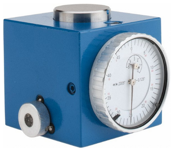

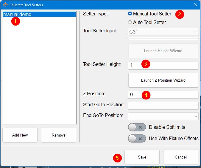
- To create a new manual tool setter, press 'Add New'. All tool setters must have a unique name. After naming the tool setter, select it from the list, and the settings for that tool setter will be shown on the right-hand side.
- Select the setter type to be manual.
- Measure the height of your setter, and enter it into the Tool Setter Height field.
- The Z position for the tool setter should be the machine coordinate for the surface the tool setter is sitting on.
- If the tool setter is permanently mounted and the Z position does not change, the Z position wizard can be used to determine this number. Once it is set correctly, it will not need to be changed. Set a GoTo position so that the spindle will always go to the setter before touching off. If the setter is mounted outside of soft limits, toggle 'Disable Softlimits'.
- If the tool setter is used in random locations, or the table height changes, then set the Z position to 0.0 and leave the GoTo positions blank.
- Click Save
Using a randomly placed tool setter

- Remove all tools from the spindle, and touch off the manual setter or gauge blocks. If your spindle uses tool holders or collets, insert an empty holder into the spindle while setting the Z position.
- Click the Set Position button. This will use the position of the tip of your spindle and the height of your setter to set the Z position.
- Insert and measure each of the tools you need for this job.
Creating an Auto Tool Setter
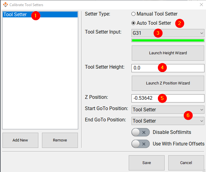 |
|
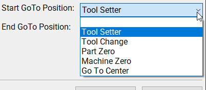
- Add a new tool setter with an appropriate name
- Select the setter type to be auto.
- Select the probe input the setter is wired to. The bar below the input selector will turn green when the tool setter is triggered. You, or a helper, can manually trigger the setter to confirm that you have the correct input.
- If the tool setter height is known, its height should be entered. If the tool setter height is not known, launch the height wizard and follow the instructions for measuring. This will require the tool setter to be wired to the control.
- The Z position for the tool setter should be the machine coordinate for the surface the tool setter is sitting on. The Z position wizard can be used to determine this number if it is not known. If the tool setter is randomly placed, not fixed, then this value will be set to 0.0 here, and will be set each time before you begin measuring tools. See the instructions above: Using a randomly placed tool setter
- Optionally, select goto positions to be associated with this tool setter.
- Selecting a position will cause the machine to go to that position before touching off with this setter. That works very well with a permanently mounted setter. If the position is outside of soft limits, turning on 'disable softlimits' will be needed to reach the setter.
- With a randomly placed setter, leave these fields blank. Either jog the spindle to the setter, or move the setter to the spindle. When you begin the process, there will be no automatic jogging.
Creating a Tool Setter Go-To Position
This is documented in Modifying GoTo Positions
Align Tool Edge to Center of Tool Setter
This feature will position the edge of the tool to the center of the tool setter. To begin using this feature set the parameter Tool Setter Align Tool Edge To Setter to Yes. Next configure the parameter "Tool Setter Align Tool Edge Offset" and choose between using "Tool Radius" or "Tool Setter Offset" as the source for the offset needed to align the tool edge to the center of the setter. Lastly choose which direction to offset when aligning the tool edge to the center.
Configure the following Parameters:
| Parameter Name | Value | Optional Values | Default Values |
| Tool Setter Align Tool Edge To Setter | Yes | No | |
| Tool Setter Align Tool Edge Offset | Tool Setter Offset | Tool Radius, Tool Setter Offset | Tool Radius |
| Tool Setter Align (X or Y) Axis To Setter | X Positive | X Positive, X Negative, Y Positive, Y Negative | X Positive |
Parameter "Tool Setter Align Tool Edge Offset" must be set to "Tool Setter Offset" before the Tool Setter Offset column will show up in the tool table.
View and Edit the tool table directly
In the upper left corner of the Tools tab is the Tool Table button
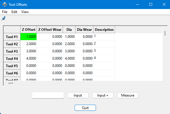
This table can be customized extensively to meet the needs of your system. Please see Tool Offset Table Customization
Start-Up Procedure

Warranty Information
MachMotion warranty policy is subject to change. Updated information is available at our website:
https://machmotion.com/warranty
The MachMotion Team
http://www.machmotion.com
14518 County Road 7240, Newburg, MO 65550
(573) 368-7399 • Fax (573) 341-2672
The MachLabs Team
http://www.mach-labs.com
14518 County Road 7240, Newburg, MO 65550
support@machsupport.com