Yaskawa V1000 / A1000 / GA500 VFD Installation
{{@672}}

1. Wiring
Control Cable: The VFD Control cable is the green Ethernet cable that runs from the Yaskawa VFD to the Control PC as shown in Figure 1. Or if you have an Apollo III motion controller, connect the VFD control cable into Ethernet 1 Port on the Apollo III.

(Figure 1 Ethernet Connection to Control PC)
Spindle Motor: Connect your spindle motor to the terminals labeled U/T1,V/T2, and W/T3 as shown in Figure 2. If your spindle moves the wrong direction when you turn it on, just swap any three of the (U,V,W) leads.

(Figure 2 Spindle Motor Connections)
Brake Resistor: Connect your brake resistor by placing the two wires on the +2/B1 and B2 terminals as shown in Figure 3.
(Note: If needed to extend the wires use High Temp rated wire.)
Mount Resistor: Mount the resistor to the cabinet. Wire as shown in Figure 3.
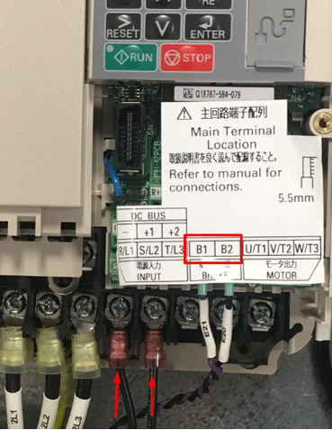
(Figure 3 Yaskawa Resistor Connections)
Thermistor: If your spindle has a thermistor, please make sure to connect it. Use the following knowledge base from Yaskawa for more information: Motor Protection Using Positive Temperature Coefficient (PTC) Thermistors. You must also switch the A3 dip switch (analog 3 input) to Voltage.
2. Programming
VFD Programming
To program the VFD you will need to utilize the Mach4 software. While the control is disabled follow the next few steps.
Step 1: Click on Configure -> Plugins -> MachMotion (as shown in the pink box in Figure 4).

(Figure 4 Access the MachMotion Plugin)
Step 2: While in the MachMotion Plugin Type "Yaskawa" in the search field as shown in Figure 5.

(Figure 5 Search Field)
Step 3: This will populate the parameters for the Yaskawa VFD V1000 (as shown below).
Note: All Mach Parameters will be labeled as "Yaskawa V1000_0" for V1000, A1000 and GA500 type VFDs.
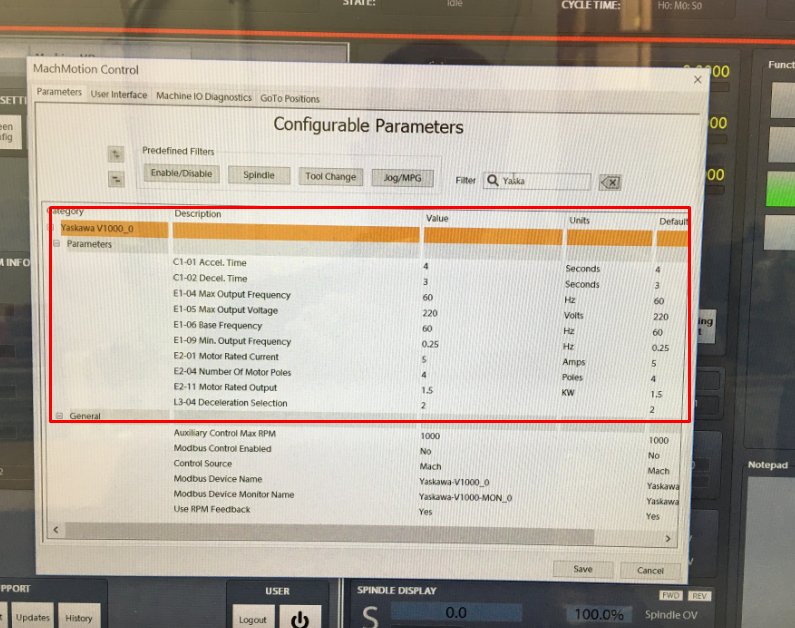
(Figure 6 Yaskawa V1000 Default Parameters)
Step 4: Enable the VFD.
For a main spindle, set Control Source to Mach and Modbus Control Enabled to Yes. For any other spindle like a grind wheel, regulating wheel, or sub spindle, set Control Source to Auxiliary and Modbus Control Enabled to Yes.
For large VFDs you must also select Drive Capacity to Large or the VFD will run at only 10% of the commanded speed. Set the Drive Capacity according to this table: https://support.machmotion.com/books/motors-drives-and-vfds/page/yaskawa-vfd-capacity-tables.
Step 5: Set up the motor parameters
Find your motor nameplate and enter in the parameters based on the table below.
If you cannot locate the motor’s base frequency, the name plate should tell you how many poles there are on the motor. You can also call the motor manufacturer to figure out the number of poles. Using the motor’s maximum RPM and its number of poles, you can calculate the base frequency with the formula below:
Motor Poles = 120 * Max Hz / Max RPM
Base Frequency = Rated RPM * Number of Poles / 120
Max Frequency = Max RPM * Number of Poles / 120
Yaskawa V1000 Parameters
| Parameters | Description | Default | Range |
| C1-01 | Accel. Time | 4 Seconds | 0.0 to 600.0 Seconds |
| C1-02 | Decel. Time | 3 Seconds | 0.0 to 600.0 Seconds |
| E1-04 | Max. Output Freq. | 60 Hz | 40.0 to 400.0 Hz |
| E1-05 | Max. Output Voltage | 220 Volts | 1.0 to 510.0 Volts |
| E1-06 | Base Frequency | 60 Hz | 1.0 to 599.0 Hz |
| E1-09 | Min. Output Freq. | 0.25 Hz | 0.0 to 599.0 Hz |
| E2-01 | Motor Rated Current | 5 Amps | 10% to 200% of drive rated current |
| E2-04 | Number of Motor Poles | 4 Poles | 2 to 20 Poles |
| E2-11 | Motor Rated Output | 1.5 kW |
0.00 to 650.00 kW |
| E2-03 | No Load Current | 40% of Motor Rated Current | |
| L3-04 | Deceleration Selection | 0 |
0 to 7 0 = Brake Resistor 1 = No Brake Resistor 2 = Default |
| C1-09 | Emergency Stop Deceleration | 3 Seconds |
0.0 to 600.0 Seconds (This parameter must be changed inside the VFD at this point) |
| L8-07 | LF Output Phase Loss | 0 |
Sometimes we need to set this to 0 to disable that alarm |
| C6-02 | Carrier Frequency Selection | 02 |
Used on High Speed Spindles to set Carrier Frequency to 5KHz |
Any time you change any of the E1 or E2 parameters, you must restart Mach4 to get the new parameters to download into the VFD.
Overspeed a Motor
If you want to command your spindle motor or grinding wheel to go faster than the base frequency, command the spindle to go max RPM and use a tachometer to measure the speed. Then use the following formula to calculate your new Max Output Frequency (E1-04):
Desired Max RPM * Current Max Frequency / Current Max RPM = New Max Frequency
For example, if your Current Max Frequency is 60 and you measure the spindle runs 1030 RPM but you actually want it to go 1515 RPM, calculate your new Max Frequency as follows:
1515 * 60 / 1030=88 Hz.
Make sure to recalibrate your RPM feedback and your spindle speed as both shown below.
Calibrate Spindle Speed
If your V1000 is setup as a Mach spindle (under MachMotion Parameters), click on Configure -> Control at top of the Mach screen. Then select the "Spindle" tab shown in Figure 7. Set your max spindle RPM for each spindle range here.

(Figure 7 Spindle Tab)
If your VFD is enabled as an Auxiliary spindle (under MachMotion Parameters), set the Auxiliary Control Max RPM to the max RPM of the motor.

Calibrate RPM Feedback
If your VFD is enabled as a Mach spindle (and there can only be one enabled at a time), follow the procedure below.
You will need to scale your emulated RPM feedback in the Mach software. Calculate your feedback ratio as follows:
- Max Spindle RPM / 3600 = Feedback Ratio
Then while the control is disabled follow the next few steps:
Step 1: Click on Configure -> Control at top of the Mach screen. Then select the "Spindle" tab shown in Figure 7.
(Figure 7 Spindle Tab)
Step 2: Enter in the value you calculated in FeedBack Ratio from the calculation you have done for Spindle Gear 1 as shown in Figure 8.

(Figure 8 Enter Feedback Ratio)
Troubleshooting
Deceleration
If you have issues getting the spindle to stop completely try setting B2-04 to 2.00sec
RPM Incorrect
If the VFD is setup correctly but the VFD does not go the correct RPM, check the S7 input. For a delayed safety relay S7 must be set to Fast Stop (N/C) or H1-07: 17. By default Yaskawa sets S7 to Fast Jog which will allow the VFD to run when you command it but only at a locked speed and only in one directly (one direction as far as we know). For more information, see Yaskawa V1000 / A1000 / GA500 / GA800 TCP Modbus Communication Setup.
Webpage
For TCP modbus VFDs, you can go to the webpage to view the status of the VFD. Normally the IP address is 192.168.208.90.
VFD Monitor Panel
You can use this panel to test VFD operation.

Alarms
If you were to get an alarm on the VFD you will receive a message on the computer screen from the Global Message System. In the description of the alarm it will describe the necessary steps to try to resolve the alarm.
Setup Verification
To test any modbus VFD, review the following items to confirm it is setup correctly:
Does the VFD run the spindle? The VFD RUN light should be on solid when it is up to speed. If it isn't, the VFD is not programmed correctly.
Does the RPM change when you change the spindle speed on the control?
Does the VFD go both directions?
If you disconnect the VFD control cable does the control time out with a VFD Disconnected Error?
Is the RPM feedback correct?
Does up to speed and at speed work correctly inside the control?
SCF Fault
Although the Yaskawa manual says it's only caused be a safety relay input issue (and likely a bad drive), we've found that DC injection braking can cause this to fault. Disable DC injection breaking and it should fix it.
Appendix
Default IO Mapping
Modbus
Inputs

Outputs - none required.
Spindle Load

Apollo III
Make sure the VFD is powered all the time. Otherwise the VFD will not connect correctly.
Wire the Estop circuit as shown below:

{{@677}}