Servos
Yaskawa Servos
Sigma 7 Series
EtherCAT Setup
Leadshine Servos
L7N
EtherCAT Setup
| Parameter | Description | Value | Activation | Index |
|---|---|---|---|---|
| PA0.08 | 1st command pulse count per revolution | 131072 | Restart | 0x2008 |
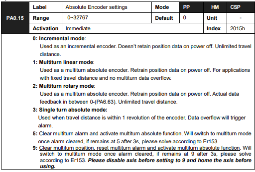
| PA0.15 | Absolute Encoder settings | 1: Activate multi… | Restart | 0x2015 |
| PA4.00 | Input selection DI1 | 0x0: [0] Invalid i… | Immediate | 0x2400 |
| PA4.01 | Input selection DI2 | 0x0: [0] Invalid i… | Immediate | 0x2401 |
| PA4.02 | Input selection DI3 | 0x0: [0] Invalid i… | Immediate | 0x2402 |
| PA4.03 | Input selection DI4 | 0x0: [0] Invalid i… | Immediate | 0x2403 |
| PA4.04 | Input selection DI5 | 0x0: [0] Invalid i… | Immediate | 0x2404 |
| PA4.05 | Input selection DI6 | 0x0: [0] Invalid i… | Immediate | 0x2405 |
| PA4.10 | Output selection DO1 | 0x0: [0] Invalid i… | Immediate | 0x2410 |
| PA4.11 | Output selection DO2 | 0x0: [0] Invalid i… | Immediate | 0x2411 |
| PA4.12 | Output selection DO3 | 0x0: [0] Invalid i… | Immediate | 0x2412 |
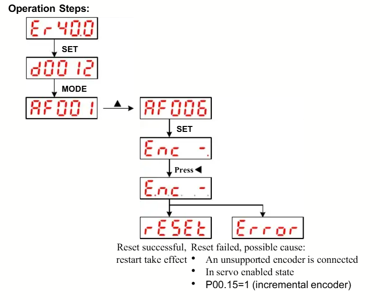
If you using absolute encoders, after cycling power turn PA0.15 to 9 and power cycle again.
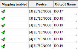
PA4.10 – PA4.12 corresponds to DO1 – DO3. If all parameters are set to 0, master device
controls the outputs, object dictionary 0x60FE sub-index 01 bit 16 to bit 18 corresponds to
DO1-DO3.
| Output Name in Mach | Digital Output on Drive |
| DO.17 | DO1 |
| DO.18 | DO2 |
| DO.19 | DO3 |
Here is an example of mapping outputs:
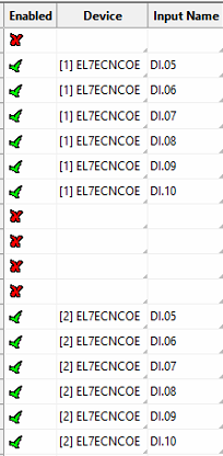
PA4.00 – PA4.05 corresponds to DI1 – DI6. External sensors can be connected if the
parameters are all set to 0. Controller will read 60FD bit 4 – bit 9 to get DI1 – DI6 actual status.
| Input Name in Mach | Digital Input on Drive |
| DI.05 | DI1 |
| DI.06 | DI2 |
| DI.07 | DI3 |
| DI.08 | DI4 |
| DI.09 | DI5 |
| DI.10 | DI6 |
Here is an example of mapping outputs:
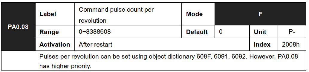
Note: To manually write to parameters from the EC-Link, you can use a configuration as follows. This is for writing to P00.08 index 0x2008.

PA0.08 is Index 2008h as shown below.
EL7
EtherCAT Setup
Same as above.
Weihong Servos
WSD-B1
EtherCAT Setup
Must reset absolute encoder alarm.