MachPro Mill and Router Setup Manual
![]()
Configure Software
Please refer to your motion controller's documentation to:
- Calibrate your axes
- Establish machine zero
- Configure soft limits
- Connect and configure I/O
Spindle Calibration
This is primarily for mills where the speeds and feeds are precise, and directly affect the finish and accuracy of the final part. Spindle speeds on routers are usually not as precise.
Spindle Settings
These are the settings for the most commonly used Spindle features.
- Pull down Configure -> Control -> Settings tab
- Click the
 button to flatten the full settings tree, then expand the Spindle section


Gear shifter
Before configuring the gear shifter, you need to configure your gear ranges. Use this portion of the Spindle Calibration document for gear range configuration. Set MaxRPM values for each gear
The default settings will work for a machine with a manual gear shifter.
You may use M-codes to run the gear change cycle during a job. M40 - M45 change ranges from 0 to 5. M40 P# can also be used where # is the gear range to use
Load
Connect your encoder to an analog input and map the Spindle Load Meter Register to that input
Orient
MachPro uses M19 to run the orient sequence.
The two primary ways to use it are in Manual or Automatic mode
For Manual mode, the default configuration will work without any changes
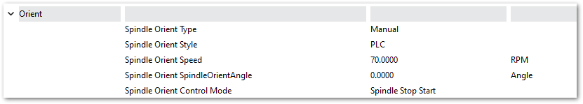
For Automatic mode configure:
- Spindle Orient Type Auto
- Spindle Orient Style Macro
- Spindle Orient Output
- Spindle Orient Input

You may change the other parameters according to what your system needs.
Sub Spindle
The minimum settings that need to be configured for the subspindle are:
- Sub Spindle Enabled
- Sub Spindle CW output
- Sub Spindle CCW output
- Sub Spindle Max RPM

Use M-codes to control the sub spindle
- M013 CW start
- M104 CCW start
- M105 stop
Global Monitoring System (GMS)
Configure the Global Monitoring System
Global Monitoring is used to setup user alerts or messages as well as to control I/O functionality based on certain conditions. The system allows the machine to watch for specified conditions, and take action when those conditions are met.
To set up the Global Monitoring System go to Configuration -> Plugins -> Global Monitoring System.

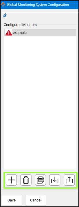
Working with configured monitors
|
The monitoring system provides five main functions for managing monitors: 1. Create a Monitor
2. Delete a Monitor
3. Duplicate a Monitor
4. Import Monitors
5. Export Monitors
Active Monitor The monitor selected in the leftmost list is the one currently active for editing. |
 |
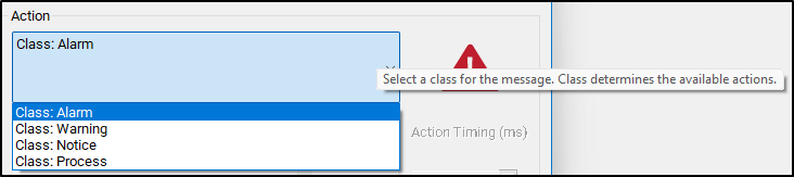
Configure Monitor Class
The monitoring system can initiate four classes of actions: Alarm, Warning, Notice, and Process.
Each class defines how the system responds to detected conditions.
1. Alarm
-
Used for emergency conditions.
-
Can take immediate safety actions, such as:
-
Disabling the machine.
-
Stopping all motion.
-
-
Requires operator intervention before restarting.
2. Warning
-
Used for non-critical issues that still require attention.
-
Can perform various automated actions.
-
Prevents Cycle Start while active.
-
Alerts the operator through a visible or audible signal.
3. Notice
-
Used for informational messages only.
-
Takes no automatic actions.
-
Displays a message to the operator for awareness.
4. Process
-
Used for background control actions.
-
Has the same potential actions as a Warning,
but does not alert the operator and does not block Cycle Start.
Tip: Use Alarm for safety-critical faults, Warning for operational issues, Notice for information, and Process for silent automation tasks.
 Configure Monitor Actions
After selecting the Action Class, you can define the specific action the monitor performs when it becomes active.
Primary and Secondary Actions
-
Each monitor has one primary action.
-
Some actions allow a secondary action.
-
Example:
-
A Warning with Action: Escalate to Alarm can trigger a chosen Alarm action after a delay.
-
-
Action Timing
-
The Action Timing field defines the delay (in milliseconds) between the first and second actions.
Example:
If Action Timing = 5000, the secondary action runs 5 seconds after the primary action.If Action Timing = 1, the secondary action runs 1/1000 of a second after the primary action - and that is very short
Set longer rather than shorter timings. It is possible to overwhelm your computer with timings that are too short. For actions that need a quick response, start with 500 and only decrease if you need to.
Repeating Actions
-
You can configure the monitor to repeat actions while it remains active.
-
When enabled:
-
The monitor executes the first action.
-
Waits for the defined Action Timing period.
-
Executes the second action (if configured).
-
Repeats this cycle until the monitor condition is no longer active.
-
Tip: Use repeating actions for persistent conditions that require continuous alerts or repeated control signals.

Custom Monitor Actions
If the standard actions do not meet your needs, you can create custom actions for the Warning and Process classes.
Enabling Custom Actions
-
In the Action List, select Custom.
-
Click the Customize button next to the action field.
-
This button is only active when Custom is selected.
-
-
A Custom Action Editor window will open.
Building a Custom Action List
In the Custom Action Editor, you can define a sequence of actions that occur when the monitor activates.
Steps:
-
Select an Action Type – Choose what kind of task the monitor will perform.
-
Fill in Action Details – Provide required parameters or settings.
-
Press Add Action – Adds the defined action to the custom action list.
Managing the Action List
-
Reorder actions:
Select an item and use the up or down arrow buttons to change its order. -
Remove an action:
Select it and press the red X button.
The monitor will execute the actions in the listed order each time it is activated.


An item can be double-clicked on to be edited, and then you should press Update Action to save your changes.
Items will be resolved sequentially in the order they appear in the list, with no pauses in between items.
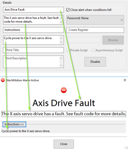
Monitor Details
Most monitors display an alert when their conditions are triggered.
All alert information and related settings are managed in the Details section of the monitor configuration.
Alert Information
-
The Details section controls what information appears in the alert message when the monitor activates.
-
You can edit titles, messages, and other displayed text from this section.
Password Protection
-
You can password-protect a monitor from the Details section.
-
When enabled:
-
The password is required to edit the monitor.
-
The password is also required to clear the monitor after activation.
-
Register Output
-
The monitor can write its current status to a register.
-
The register includes:
-
Enabled/Disabled state.
-
Idle/Active state.
-
-
Use this to track monitor states through external systems or scripts.
Script Execution
-
If the selected action is Execute Script, configure the script in this section.
-
Specify the script file name with the
.mcsextension.-
Example:
MonitorAlert.mcs
-
Disabling a Monitor
-
You can disable the entire monitor without deleting it.
-
A disabled monitor will:
-
Not check its conditions.
-
Not perform any actions.
-
-
Re-enable it later to restore normal operation.


Set Monitor Conditions
A monitor will do its configured action based on the conditions that are set for it. To edit these conditions, you will need to select the Edit Conditions button. The following window will be displayed.

Monitor conditions define when a monitor becomes active.
They are organized into sets and items, which together form the logical rules that trigger a monitor.
Structure Overview
-
Sets: Groups that define the logical relationship between their items or subsets.
-
Items: Individual conditions within a set.
-
Subsets: Nested sets that allow complex logical combinations.
Set Types
Each set can be one of three logic types:
Set Type Logic Description AND True only if all contained items and subsets are true. OR True if at least one item or subset is true. NOT True only if all contained items and subsets are false. Tip: Most monitors only require a single AND set.
Adding Sets
-
Select the parent set where the new set should belong.
-
Choose the set type (AND, OR, or NOT) from the list.
-
Press Add Set.
This creates a new logic group inside the parent set.
Adding Items (Conditions)

-
Select an item type from the dropdown menu.
-
Fill in the condition details.
-
Press Add Condition to include it in the selected set.
Example: Machine Enabled Condition
To add a condition that requires the machine to be enabled:
-
Choose Condition Type: Signal.
-
Select Output Signals.
-
Choose Machine Enabled.
-
Press Add Condition.
Editing Sets and Conditions
-
Edit a set:
Double-click the set in the left-hand list, change the set type, then press Update. -
Edit a condition:
Double-click the condition, modify the details, then press Update.
Saving Changes
-
Press OK to save all modifications.
-
Press Cancel to discard any unsaved changes.

Save All Changes
Pressing Save will save changes to all monitors and exit config. Pressing Cancel will discard all changes and exit config.

Common GMS Templates
See the attached ini files to download and import standard GMS functions.
SpindleWarmupBackup.ini
If you run a file when the spindle is not warmed up, it will warm up the spindle and then go ahead and run the file. As a safety feature, you can prevent a file from starting until spindle warmup is completed to avoid this issue.
Diagnostics Window
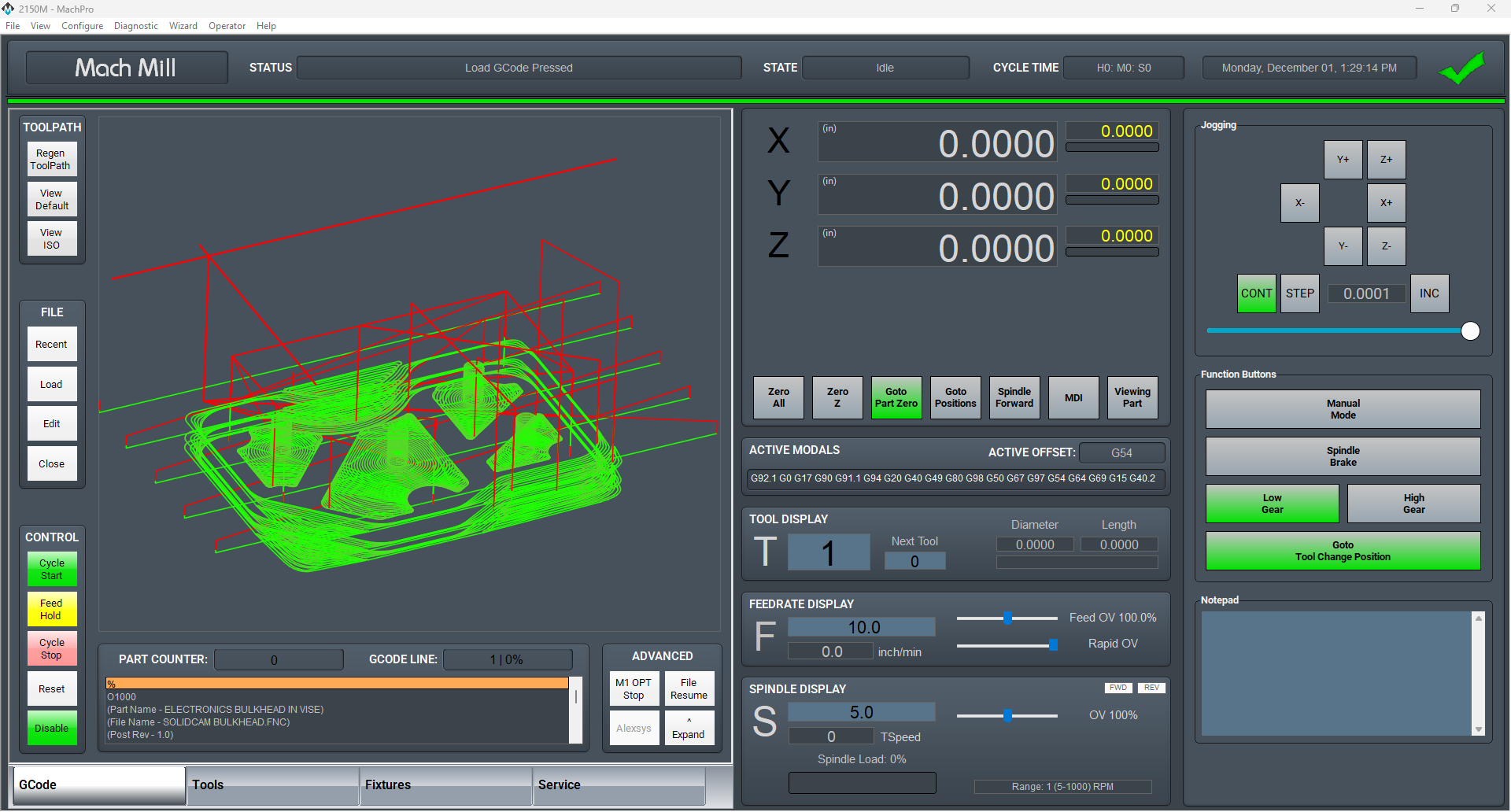
The Global Monitoring System icon is on most screens, and will indicate if there is currently an alarm or warning active. If there are no alarms or warnings active, then the icon will be a green checkmark. If there is an alarm or warning active, it will flash a red and yellow error triangle. Clicking on the icon will open the diagnostics window.


The diagnostics window will show all configured monitors and their data. The condition tree will show the state of each condition by highlighting true conditions in green. A red condition means that the condition is incorrectly configured and cannot be checked.
Alarms and warnings must be cleared to operate the machine. Pressing Reset on the operator panel will clear alarms. They can also be cleared in the diagnostics be clicking Clear All. Resetting a monitor will transition the monitor back to the idle state and reset the timers on all conditions. If the conditions on a monitor are still true, then the monitor will activate again immediately.
A monitor can be temporarily disabled here. The monitor will continue to check it's conditions and change states, but will not take any actions when it transitions out of the idle state. The monitor will re-enable itself when it transitions back to idle state or when the operator enables it again.

-


Lube System Setup
If your system has an oiler edit the lube settings. Pull down Configure -> Control, and select the Settings Tab. Scroll down to the Lube System settings. Enable the lube system, and adjust the settings. In the default settings, the oiler will only run while the control is enabled, and it will run for 8 seconds, then turn off for 5 minutes. Adjust the values according to your machine's needs. Note that lube pumps vary widely in their output. Start conservatively and increase the values to achieve proper lubrication.

Tool Setters and Offsets
Open the Calibrate Tool Setters window. Found on the Tools tab.

Creating a Manual Tool Setter
Mapping the input to a software signal
Pull down Configure -> Control and select the Input Signals tab.
Some signals are pre-configured when MachPro is installed.
Tool Setter Limit (Over Travel) maybe be mapped to Input #6
Tool Setter Input may be mapped to Probe1.
|
|
|
|


GoTo Position
-
If the tool setter is permanently mounted, then define a GoTo Position so the spindle can safely move to the tool setter before touch-off.
-
This ensures a consistent and safe approach, reducing the risk of collisions.
1. Add or Edit a tool setter
-
In the Tool Setter tab, click Add New to create a new tool setter.
-
Enter a unique name for the tool setter.
-
Select the new tool setter from the list to display its settings on the right side.
2. Setter Type
-
Under Setter Type, select Manual.
3. Tool Setter Height
- This is used with randomly placed tool setters to determine the Z fixture offset. If you have a fixed position tool setter, leave this value at 0.0
-
Measure the physical height of the tool setter.
-
Enter the measured value in the Tool Setter Height field.
4. Z Position
-
For a fixed positionsetter:
-
Use the Z Position Wizard to determine the machine coordinate for the top surface of the setter.
-
Once set correctly, this value should not be changed.
-
-
If the setter is mounted outside the soft limits, enable Disable Softlimits.
- Once the Z position and height are calibrated, the system will automatically use these values for all tool length offset calculations.
Randomly placed tool setter
-
Set Initial Parameters
-
Set the Z Position to 0.0.
-
Leave all GoTo fields blank.
-
This indicates that the setter position may change between uses.
-
-
Prepare the Spindle
-
Remove all tools from the spindle.
-
If the spindle uses tool holders or collets, insert an empty holder while setting the Z position.
-
-
Position the Tool Setter
-
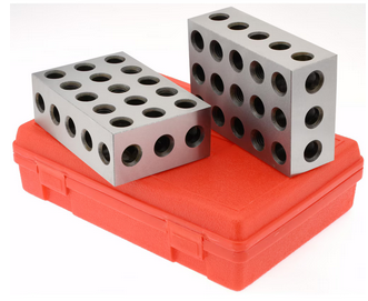
Place the manual tool setter or gauge blocks on the table at the desired location.
-
-
Set the Z Position
-
Carefully jog the spindle down until the tool tip touches the surface of the setter.
-
Click Set Position.
-
This records the Z position using the current spindle location and the entered Tool Setter Height value.
-
-
Measure Tools
-
Insert each tool required for the job.
-
Perform a tool measurement cycle for each tool to record its length offset.
-

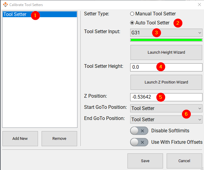
Creating an Auto Tool Setter
Click on the Tools tab at the bottom of the MachPro screen, then on the Tool Setters button in the middle of the left side of the screen.
If you are setting up a RapidChangeATC changer and setter, also refer to RapidChangeATB Tool Changer and Tool Setter
|
|
|

- Define GoTo Positions for the tool setter.
-
-
Selecting a GoTo position allows the spindle to move automatically to the setter before touching off.
-
This is recommended for permanently mounted setters.
-
If the setter is located outside the soft limits, enable Disable Softlimits.
-
-
-
Click Add New to create a new tool setter.
-
Enter an appropriate name for the tool setter.
-
-
Set the Setter Type to Auto.
-
Select the Probe Input that the tool setter is wired to. The 4 input signals available are:
- Probe (G31)
- Probe1 (G31.1)
- Probe2 (G31.2)
- Probe3 (G31.3)
-
If the correct input probe signal has been selected, then indicator bar below the input selector will turn green when the tool setter is triggered. Manually trigger the setter (or have a helper do so) to confirm the correct input is selected.
-
If the tool setter height is known, enter the value in the Tool Setter Height field.
-
If the height is unknown, click Launch Height Wizard and follow the on-screen instructions to measure it.
-
The tool setter must be wired to the control for this process.
-
-
Set the Z Position to the machine coordinate of the surface where the tool setter rests.
-
If the position is unknown, use the Z Position Wizard to determine it.
-
For a randomly placed setter, set the Z Position to 0.0. This value will be defined each time before measuring tools.
-
See also: Using a Randomly Placed Tool Setter.
-
-
For randomly placed setters, leave all GoTo Position fields blank.
-
Manually jog the spindle to the setter or place the setter beneath the spindle as needed.
-
The machine will not perform automatic jogging during this process.
-
Align Tool Edge to Center of Tool Setter
This feature positions the edge of the tool precisely at the center of the tool setter, ensuring accurate alignment and consistent measurement results.
Pull down Configure -> Control and select the Settings Tab. Scroll down to the Measurements and Offsets section.

-
Set Tool Setter Align Tool Edge To Setter to Yes.
-
Configure the Tool Setter Align Tool Edge Offset parameter.
-
Choose between Tool Radius or Tool Setter Offset as the source for the offset used to align the tool edge to the center of the setter.
-
-
Select whether to Align (X or Y) Axis to Setter to define which way the tool moves when aligning the edge to the center of the setter.
- Close the Settings menu
- If you selected Tool Setter Offset, then open the Tool Table and click the Edit option
- Select the User Fields tab
- Select the Tool Setter Offset field, and use the movement buttons to place the field where you want within the User Fields
- Close the Tool Table Editor
- Select View and select User Fields
|
|
|


Additional Settings
The measuring and offsets settings in MachPro Control may provide helpful access to these settings. Pull down Configure -> Control and select the Settings Tab and scroll down to the Measuring and Offsets portion.

Probing Wizard
Tool nose radius compensation provides a way to perform precise cutting with a tool that doesn't end in a perfect point. Since no tool has a perfect point, the sharpness of the point be expressed in the radius of the tool nose (the smaller the radius, the sharper the point).
Here is an illustration of a realistic cutting tool tip. The tool nose radius is exaggerated to better illustrate the idea that the theoretical tip (commanded) position (illustrated with a red +) is not in the same place as the actual cutting edge of the tip (highlighted with purple).

Example
Suppose you wish to cut this profile (with a tool tip of type 3):

If the cutter had a perfect point, then the commanded path would be precisely along the desired geometry path.

For a real tool, however, the nose of the cutting tool is some distance away from the point on the desired geometry. If we commanded positions along the path of the desired geometry, we would not achieve the desired geometry. The actual geometry achieved is illustrated by the blue path. Compare that with the commanded positions, illustrated with red + marks.

A real tool will not produce the desired geometry without some compensation. A compensated path (illustrated in red) would put the rounded edge of the tool nose at the correct position to produce the desired geometry (illustrated in black).

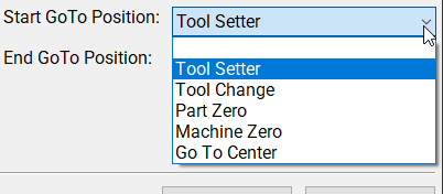
Modifying GoTo Positions
If you are setting up the GoTo position for a tool setter, jog the tool to the correct position over the tool setter.

Position Setup Instructions
-
Use the Add or Remove buttons at the bottom to manage positions.
-
When adding a new position, choose Machine Coordinates or Part Coordinates at the top.
-
To change an existing position, select it and edit as needed.
-
Each position builds a movement list in the Data Box. Use Delete to remove a movement.
- To add a custom G-code line, write it and click Add to include it in the Goto list.
⚠️ Do not use M Codes here.
This helps move the tool safely before other operations.

Add Movement Instructions
-
Click Include for each axis you want to move.
-
Click Get Current Position to copy the current coordinates, or type the coordinates manually.
-
Click Add/Update to save the movement in the Data Section.
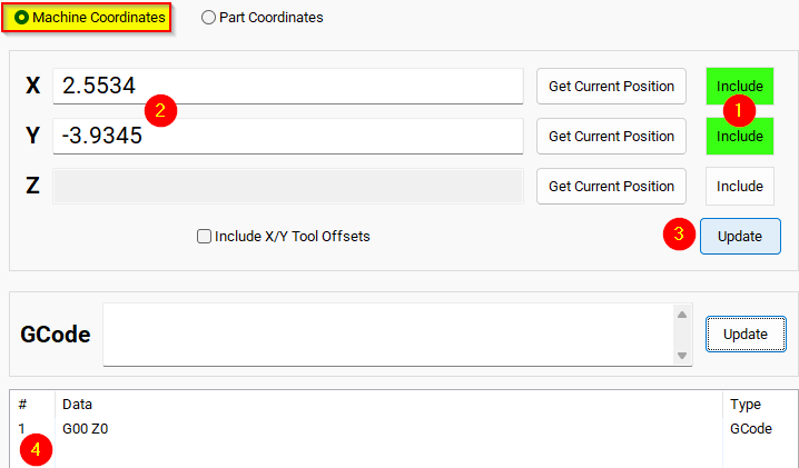
Example: Z-Axis Movement
-
Define the Z-axis movement to run first.
-
Click Add/Update to insert this movement into the Data Box.
-
Add more actions in the next rows.
-
Optionally, add a final Z Rapid Move to bring the tool close to the setter.


I modified the Tool Setter position. Coordinate lines in the Data box will be in Machine Coordinates. This will be used as the Tool Setter position and can be called using the P2 variable.
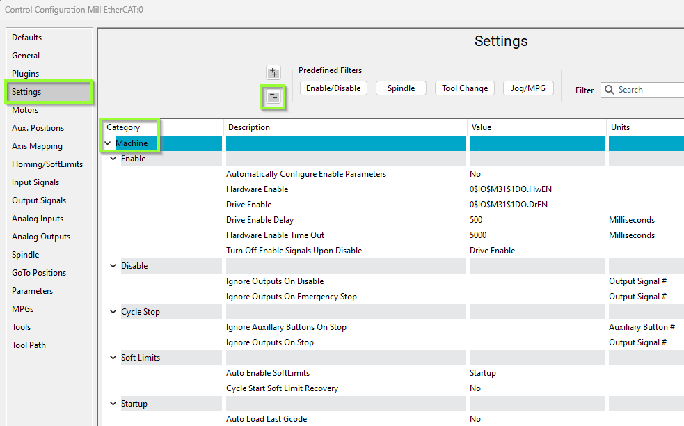
Other Machine Settings
Pull down Configure -> Control and select the Settings Tab and scroll down to the Machine section
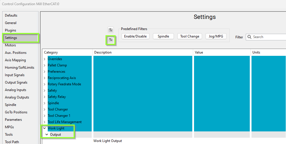
Work Light Output
Pull down Configure -> Control and select the Settings Tab and scroll down to the Work Light section
Additional Information
For information about MachPro Software Operation please see the MachPro Mill/Router Operating Manual
| http://www.mach-labs.com | MachLabs Documentation | support@mach-labs.com |
The MachLabs Team
14518 County Road 7240, Newburg, MO 65550
support@mach-labs.com