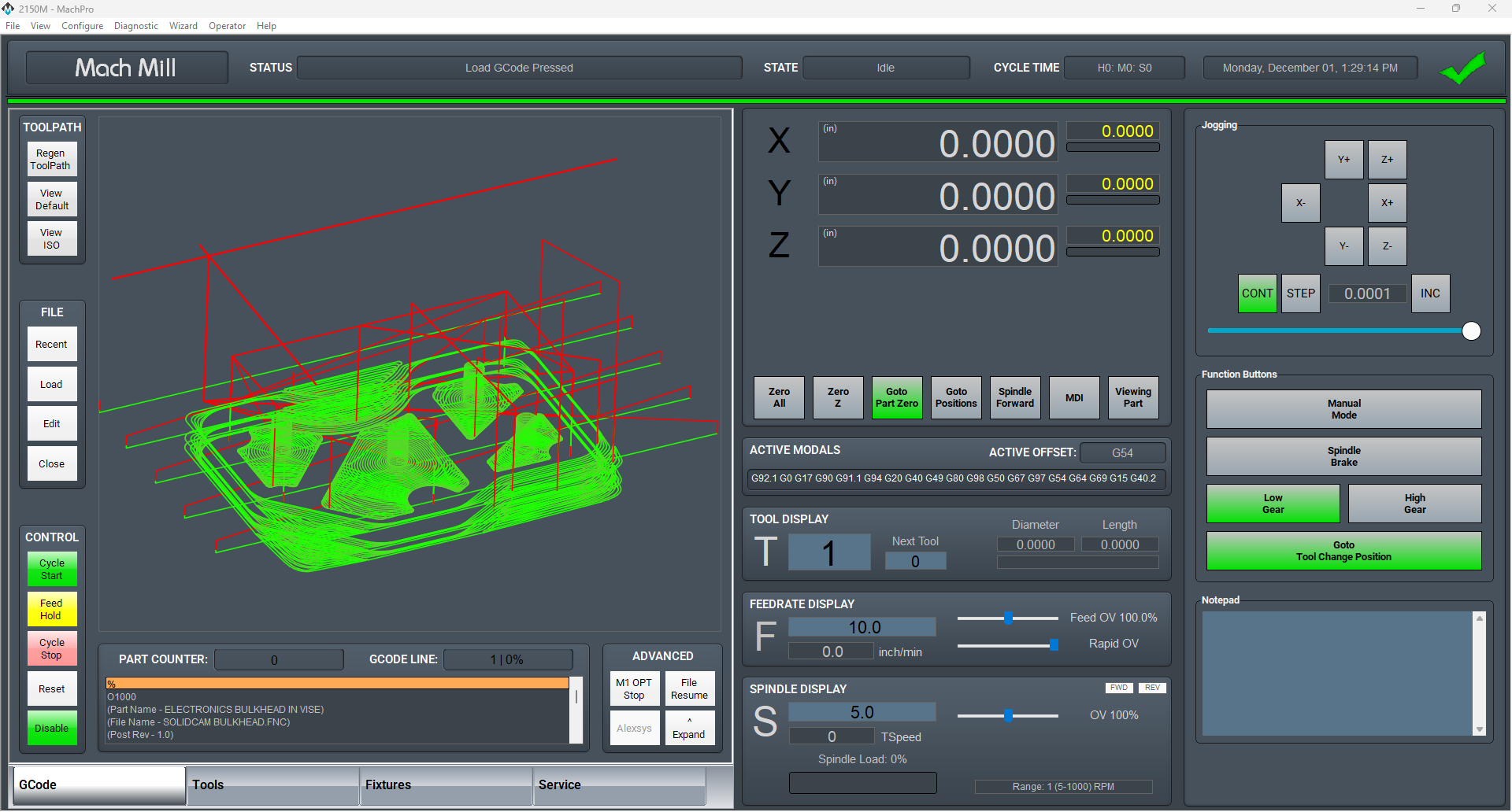
MachPro Mill and Router Setup Manual
![]()
Configure Software
Please refer to your motion controller's documentation to:
- Calibrate your axes
- Establish machine zero
- Configure soft limits
- Connect and configure I/O
Spindle Calibration
These instructions apply to all VFDs where the spindle is controlled through the MachPro Control Spindle tab
Why calibrate your spindle?
Does your CNC control need it? Mills and Lathes need to be calibrated while routers typically do not. The spindle speed needs to be accurate enough to meet your tooling specifications.
- The rated speeds and feeds for your tools and materials should perform as expected.
- You should have comparable performance across all your machines when running the same spindle speed.
- Accurate spindle calibration enables you to make cleaner and more accurate cuts – improving the quality of your final product.
- Scheduled preventative maintenance should include verification of the accuracy of the system, including the spindle speeds.
This documentation focuses on knee mills as a common example and is adaptable to other machines.
Prerequisites
- Your spindle needs to be configured according to your motion controller's capabilities for spindles.
- The axes need to be calibrated
- Machine zero and soft limits need to configured
- The I/O, particularly limits, need to be connected and working
Definitions
Machines often have both gears and speed controls.
The control needs to know which physical gear is engaged to control the spindle motor for the correct speed. If you use multiple gears on your machine, there will be gear change buttons on the screen, and you can also
The speed control is a set of variable diameter pulleys that provide a variable speed within each gear. We often set this to the maximum RPM. Then we use the VFD to provide the full speed range within each gear.
Set MaxRPM values for each gear
If you do not have a tachometer
Pull down Configure | Control | Spindle tab
If your machine only has one range (no pulleys or gears), then enter the minimum and maximum RPM for the spindle in the Range 1 row.
If you have multiple gears, enter the rated maximum RPM for each gear into the MaxRPM column for each gear.

If you have a tachometer
Use the steps below to set the MaxRPM:
- Set the spindle override knob on the operator control panel to 100%
- Temporarily set all MaxRPM values to twice the labeled RPM on the speed control. This is not to destroy your machine. For calibration purposes this forces the VFD to the maximum hertz output - therefore the maximum tool RPM. We use that to calibrate accurate tool RPM for normal production.
- Verify that the VFD is sending the maximum Hz to the spindle (see next section)
- Run your machine in each gear range with the temporary MaxRPM values you used above. Verify that the VFD is putting out maximum Hz. Record the actual MaxRPM values from the tachometer for each gear range.
- Enter the actual MaxRPM values that the tachometer reported in the spindle tab.

If it is not safe to run this spindle at its maximum RPM, please contact MachLabs for assistance with calibration.
Verify that the VFD is sending maximum speed commands to the spindle
You need to know that the VFD is telling the spindle motor to run at full speed. Assuming the motor is configured to run at 60 Hz, then if the VFD is sending 60 Hz, the motor is running at full speed. You just entered the MaxRPM values into the spindle config. Set your machine for one of the gears and run the spindle at the MaxRPM. You can check the VFD output two ways, and both are equally accurate:
|
|
|
|
With the enclosure door open, check the LED on the VFD. This VFD is running at P44.59% of 60 Hz = 26.754 Hz. The "P" prefix on the number indicates the number is a percentage.
|
Open a web browser and enter this IP address in the search bar 192.168.208.90. It will open a welcome page for the VFD with two buttons at the bottom. Click the Monitor button and look for the Output Frequency line. This is the same machine running at the same time, and it also reports 44.59% = 26.754 Hz. |


Adjust feedback ratios for TSpeed
The formula is MaxRPM / Maximum Motor RPM = feedback ratio
Pull down Configure | Control | Spindle tab

Check the ID plate on the spindle motor for RPM values. In this image we are running at 60 hertz; so we use the second value: 1735

MaxRPM from tachometer / Maximum Motor RPM = feedback ratio
4485 / 1735 = 2.5850144092219020172910662824207
You can paste the the full value into the spindle FeedBack Ratio field for this range, or just 2.58501
Note: the feedback ratio only adjusts the value in the TSpeed field. It does not have any effect on the actual RPM of the spindle. If the spindle speed reported by a tach does not match commanded speed, then go here: Set MaxRPM values for each gear
Operating the spindle
Use M-Codes to operate your spindle during production: M3, M4, and M5 (relevant portion of the G-Code and M-Code Reference)
You can manually control the spindle with the buttons on your operator panel.
Changing Gears
The gear ranges can be changed from the control by using M40-M45 in your G-Code file. These macros can be used to just change ranges or they can be used to automatically change gears on the machine if it has an automatic gear changer. To shift the machine range 0, run M40. M41 is range 1, M42 is range 2, and so on. You will be prompted to change the gear manually. M40 P# can also be used where # is the gear range to use.
Special situations
Overspeed a spindle motor
If you want to command your spindle motor or grinding wheel to go faster than the base frequency, command the spindle to go max RPM and use a tachometer to measure the speed. Then use the following formula to calculate your new Max Output Frequency (Hb105):
Desired Max RPM * Current Max Frequency / Current Max RPM = New Max Frequency
For example, if your Current Max Frequency is 60 and you measure the spindle runs 1030 RPM but you actually want it to go 1515 RPM, calculate your new Max Frequency as follows:
1515 * 60 / 1030=88 Hz.
Make sure to recalibrate your RPM feedback and your spindle speed as shown below.
Set a spindle to always run at maximum RPM
In some cases, a machine was originally configured to run the spindle motor at full speed, and the gears and speed controls are used to bring the RPM down to the required value. A motor running this way will always generate its maximum torque, which is very helpful when using large tools.
Pull down Configure | Control | Spindle tab

Set your MinRPM and MaxRPM for each gear to the same value.
Set your Max Spindle Motor RPM to the rated value listed on the spindle motor plate.
Leave the FeedBack Ratio values alone as they are no longer meaningful.
The spindle section of you screen can now be ignored. You will adjust your spindle speed entirely through the gears and speed control.

The rest of the spindle configuration above is not needed when it is configured to run maximum RPM.
Auxiliary Spindle MaxRPM
If your VFD is enabled as an Auxiliary spindle (under MachPro settings), set the Auxiliary Control Max RPM to the max RPM of the tool or table. Use this value both in the VFD configuration, and in the sub spindle configuration. Also see this section on sub spindle configuration

Spindle Settings
These are the settings for the most commonly used Spindle features.
- Pull down Configure -> Control -> Settings tab
- Click the
 button to flatten the full settings tree, then expand the Spindle section


Gear shifter
Before configuring the gear shifter, you need to configure your gear ranges. Use this portion of the Spindle Calibration document for gear range configuration. Set MaxRPM values for each gear
The default settings will work for a machine with a manual gear shifter.
You may use M-codes to run the gear change cycle during a job. M40 - M45 change ranges from 0 to 5. M40 P# can also be used where # is the gear range to use
Load
Connect your encoder to an analog input and map the Spindle Load Meter Register to that input
Orient
MachPro uses M19 to run the orient sequence.
The two primary ways to use it are in Manual or Automatic mode
For Manual mode, the default configuration will work without any changes
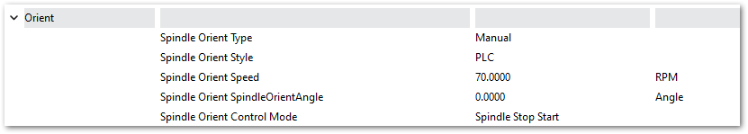
For Automatic mode configure:
- Spindle Orient Type Auto
- Spindle Orient Style Macro
- Spindle Orient Output
- Spindle Orient Input

You may change the other parameters according to what your system needs.
Sub Spindle
The minimum settings that need to be configured for the subspindle are:
- Sub Spindle Enabled
- Sub Spindle CW output
- Sub Spindle CCW output
- Sub Spindle Max RPM

Use M-codes to control the sub spindle
- M013 CW start
- M104 CCW start
- M105 stop
Lube System Setup
If your system has an oiler edit the lube settings. Pull down Configure -> Control, and select the Settings Tab. Scroll down to the Lube System settings. Enable the lube system, and adjust the settings. In the default settings, the oiler will only run while the control is enabled, and it will run for 8 seconds, then turn off for 5 minutes. Adjust the values according to your machine's needs. Note that lube pumps vary widely in their output. Start conservatively and increase the values to achieve proper lubrication.

Tool Setters and Offsets
Open the Calibrate Tool Setters window. Found on the Tools tab.

Creating a Manual Tool Setter
Mapping the input to a software signal
Pull down Configure -> Control and select the Input Signals tab.
Some signals are pre-configured when MachPro is installed.
Tool Setter Limit (Over Travel) maybe be mapped to Input #6
Tool Setter Input may be mapped to Probe1.
|
|
|
|


GoTo Position
-
If the tool setter is permanently mounted, then define a GoTo Position so the spindle can safely move to the tool setter before touch-off.
-
This ensures a consistent and safe approach, reducing the risk of collisions.
1. Add or Edit a tool setter
-
In the Tool Setter tab, click Add New to create a new tool setter.
-
Enter a unique name for the tool setter.
-
Select the new tool setter from the list to display its settings on the right side.
2. Setter Type
-
Under Setter Type, select Manual.
3. Tool Setter Height
- This is used with randomly placed tool setters to determine the Z fixture offset. If you have a fixed position tool setter, leave this value at 0.0
-
Measure the physical height of the tool setter.
-
Enter the measured value in the Tool Setter Height field.
4. Z Position
-
For a fixed positionsetter:
-
Use the Z Position Wizard to determine the machine coordinate for the top surface of the setter.
-
Once set correctly, this value should not be changed.
-
-
If the setter is mounted outside the soft limits, enable Disable Softlimits.
- Once the Z position and height are calibrated, the system will automatically use these values for all tool length offset calculations.
Randomly placed tool setter
-
Set Initial Parameters
-
Set the Z Position to 0.0.
-
Leave all GoTo fields blank.
-
This indicates that the setter position may change between uses.
-
-
Prepare the Spindle
-
Remove all tools from the spindle.
-
If the spindle uses tool holders or collets, insert an empty holder while setting the Z position.
-
-
Position the Tool Setter
-
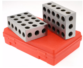
Place the manual tool setter or gauge blocks on the table at the desired location.
-
-
Set the Z Position
-
Carefully jog the spindle down until the tool tip touches the surface of the setter.
-
Click Set Position.
-
This records the Z position using the current spindle location and the entered Tool Setter Height value.
-
-
Measure Tools
-
Insert each tool required for the job.
-
Perform a tool measurement cycle for each tool to record its length offset.
-

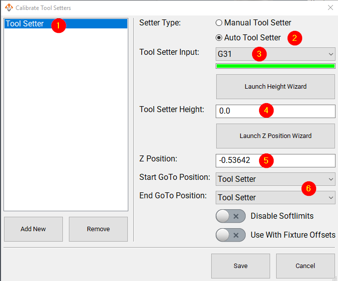
Creating an Auto Tool Setter
Click on the Tools tab at the bottom of the MachPro screen, then on the Tool Setters button in the middle of the left side of the screen.
If you are setting up a RapidChangeATC changer and setter, also refer to RapidChangeATB Tool Changer and Tool Setter
|
|
|

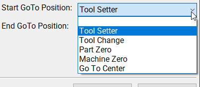
- Define GoTo Positions for the tool setter.
-
-
Selecting a GoTo position allows the spindle to move automatically to the setter before touching off.
-
This is recommended for permanently mounted setters.
-
If the setter is located outside the soft limits, enable Disable Softlimits.
-
-
-
Click Add New to create a new tool setter.
-
Enter an appropriate name for the tool setter.
-
-
Set the Setter Type to Auto.
-
Select the Probe Input that the tool setter is wired to. The 4 input signals available are:
- Probe (G31)
- Probe1 (G31.1)
- Probe2 (G31.2)
- Probe3 (G31.3)
-
If the correct input probe signal has been selected, then indicator bar below the input selector will turn green when the tool setter is triggered. Manually trigger the setter (or have a helper do so) to confirm the correct input is selected.
-
If the tool setter height is known, enter the value in the Tool Setter Height field.
-
If the height is unknown, click Launch Height Wizard and follow the on-screen instructions to measure it.
-
The tool setter must be wired to the control for this process.
-
-
Set the Z Position to the machine coordinate of the surface where the tool setter rests.
-
If the position is unknown, use the Z Position Wizard to determine it.
-
For a randomly placed setter, set the Z Position to 0.0. This value will be defined each time before measuring tools.
-
See also: Using a Randomly Placed Tool Setter.
-
-
For randomly placed setters, leave all GoTo Position fields blank.
-
Manually jog the spindle to the setter or place the setter beneath the spindle as needed.
-
The machine will not perform automatic jogging during this process.
-
Align Tool Edge to Center of Tool Setter
This feature positions the edge of the tool precisely at the center of the tool setter, ensuring accurate alignment and consistent measurement results.
Pull down Configure -> Control and select the Settings Tab. Scroll down to the Measurements and Offsets section.

-
Set Tool Setter Align Tool Edge To Setter to Yes.
-
Configure the Tool Setter Align Tool Edge Offset parameter.
-
Choose between Tool Radius or Tool Setter Offset as the source for the offset used to align the tool edge to the center of the setter.
-
-
Select whether to Align (X or Y) Axis to Setter to define which way the tool moves when aligning the edge to the center of the setter.
- Close the Settings menu
- If you selected Tool Setter Offset, then open the Tool Table and click the Edit option
- Select the User Fields tab
- Select the Tool Setter Offset field, and use the movement buttons to place the field where you want within the User Fields
- Close the Tool Table Editor
- Select View and select User Fields
|
|
|


Additional Settings
The measuring and offsets settings in MachPro Control may provide helpful access to these settings. Pull down Configure -> Control and select the Settings Tab and scroll down to the Measuring and Offsets portion.

Modifying GoTo Positions
If you are setting up the GoTo position for a tool setter, jog the tool to the correct position over the tool setter.

Position Setup Instructions
-
Use the Add or Remove buttons at the bottom to manage positions.
-
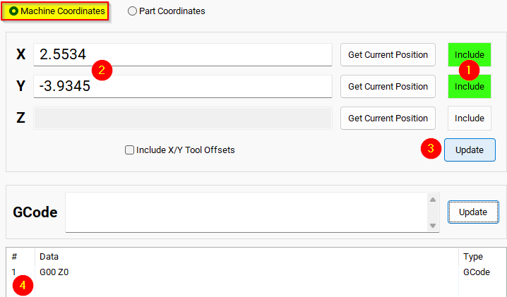
When adding a new position, choose Machine Coordinates or Part Coordinates at the top.
-
To change an existing position, select it and edit as needed.
-
Each position builds a movement list in the Data Box. Use Delete to remove a movement.
- To add a custom G-code line, write it and click Add to include it in the Goto list.
⚠️ Do not use M Codes here.
This helps move the tool safely before other operations.

Add Movement Instructions
-
Click Include for each axis you want to move.
-
Click Get Current Position to copy the current coordinates, or type the coordinates manually.
-
Click Add/Update to save the movement in the Data Section.
Example: Z-Axis Movement
-
Define the Z-axis movement to run first.
-
Click Add/Update to insert this movement into the Data Box.
-
Add more actions in the next rows.
-
Optionally, add a final Z Rapid Move to bring the tool close to the setter.


I modified the Tool Setter position. Coordinate lines in the Data box will be in Machine Coordinates. This will be used as the Tool Setter position and can be called using the P2 variable.
Additional Information
For information about MachPro Software Operation please see the MachPro Mill/Router Operating Manual
| http://www.mach-labs.com | MachLabs Documentation | support@mach-labs.com |
The MachLabs Team
14518 County Road 7240, Newburg, MO 65550
support@mach-labs.com