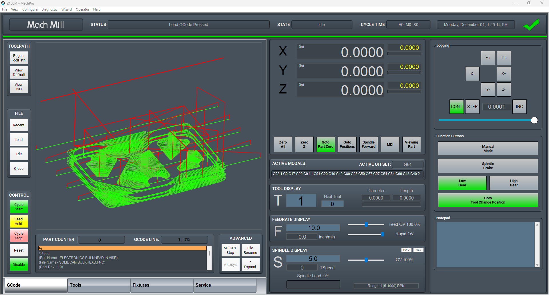
MachPro Mill and Router Setup Manual
![]()
Configure Software
Please refer to your motion controller's documentation to:
- Calibrate your axes
- Establish machine zero
- Configure soft limits
- Connect and configure I/O
Spindle Calibration
spindle include
Lube System Setup
If your system has an oiler edit the lube settings. Pull down Configure -> Control, and select the Settings Tab. Scroll down to the Lube System settings. Enable the lube system, and adjust the settings. In the default settings, the oiler will only run while the control is enabled, and it will run for 8 seconds, then turn off for 5 minutes. Adjust the values according to your machine's needs. Note that lube pumps vary widely in their output. Start conservatively and increase the values to achieve proper lubrication.

Tool Setters and Offsets
Open the Calibrate Tool Setters window. Found on the Tools tab.

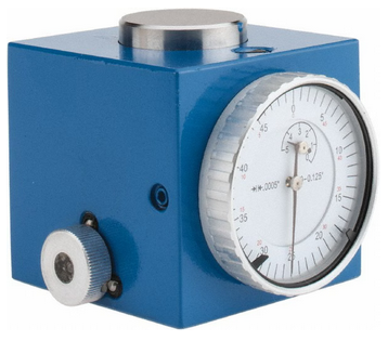
Creating a Manual Tool Setter
Mapping the input to a software signal
Pull down Configure -> Control and select the Input Signals tab.
Some signals are pre-configured when MachPro is installed.
Tool Setter Limit (Over Travel) maybe be mapped to Input #6
Tool Setter Input may be mapped to Probe1.
|
|
|
|


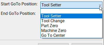
GoTo Position
-
If the tool setter is permanently mounted, then define a GoTo Position so the spindle can safely move to the tool setter before touch-off.
-
This ensures a consistent and safe approach, reducing the risk of collisions.
1. Add or Edit a tool setter
-
In the Tool Setter tab, click Add New to create a new tool setter.
-
Enter a unique name for the tool setter.
-
Select the new tool setter from the list to display its settings on the right side.
2. Setter Type
-
Under Setter Type, select Manual.
3. Tool Setter Height
- This is used with randomly placed tool setters to determine the Z fixture offset. If you have a fixed position tool setter, leave this value at 0.0
-
Measure the physical height of the tool setter.
-
Enter the measured value in the Tool Setter Height field.
4. Z Position
-
For a fixed positionsetter:
-
Use the Z Position Wizard to determine the machine coordinate for the top surface of the setter.
-
Once set correctly, this value should not be changed.
-
-
If the setter is mounted outside the soft limits, enable Disable Softlimits.
- Once the Z position and height are calibrated, the system will automatically use these values for all tool length offset calculations.
Randomly placed tool setter
-
Set Initial Parameters
-
Set the Z Position to 0.0.
-
Leave all GoTo fields blank.
-
This indicates that the setter position may change between uses.
-
-
Prepare the Spindle
-
Remove all tools from the spindle.
-
If the spindle uses tool holders or collets, insert an empty holder while setting the Z position.
-
-
Position the Tool Setter
-
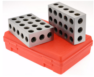
Place the manual tool setter or gauge blocks on the table at the desired location.
-
-
Set the Z Position
-
Carefully jog the spindle down until the tool tip touches the surface of the setter.
-
Click Set Position.
-
This records the Z position using the current spindle location and the entered Tool Setter Height value.
-
-
Measure Tools
-
Insert each tool required for the job.
-
Perform a tool measurement cycle for each tool to record its length offset.
-

Creating an Auto Tool Setter
Click on the Tools tab at the bottom of the MachPro screen, then on the Tool Setters button in the middle of the left side of the screen.
If you are setting up a RapidChangeATC changer and setter, also refer to RapidChangeATB Tool Changer and Tool Setter
|
|
|

- Define GoTo Positions for the tool setter.
-
-
Selecting a GoTo position allows the spindle to move automatically to the setter before touching off.
-
This is recommended for permanently mounted setters.
-
If the setter is located outside the soft limits, enable Disable Softlimits.
-
-
-
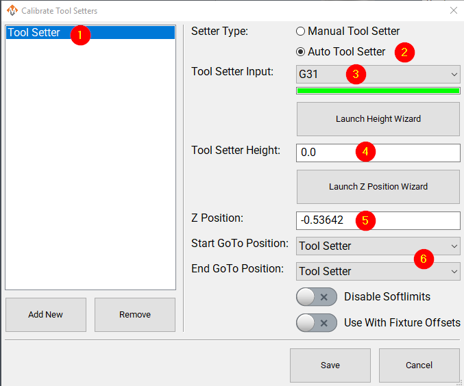
Click Add New to create a new tool setter.
-
Enter an appropriate name for the tool setter.
-
-
Set the Setter Type to Auto.
-
Select the Probe Input that the tool setter is wired to. The 4 input signals available are:
- Probe (G31)
- Probe1 (G31.1)
- Probe2 (G31.2)
- Probe3 (G31.3)
-
If the correct input probe signal has been selected, then indicator bar below the input selector will turn green when the tool setter is triggered. Manually trigger the setter (or have a helper do so) to confirm the correct input is selected.
-
If the tool setter height is known, enter the value in the Tool Setter Height field.
-
If the height is unknown, click Launch Height Wizard and follow the on-screen instructions to measure it.
-
The tool setter must be wired to the control for this process.
-
-
Set the Z Position to the machine coordinate of the surface where the tool setter rests.
-
If the position is unknown, use the Z Position Wizard to determine it.
-
For a randomly placed setter, set the Z Position to 0.0. This value will be defined each time before measuring tools.
-
See also: Using a Randomly Placed Tool Setter.
-
-
For randomly placed setters, leave all GoTo Position fields blank.
-
Manually jog the spindle to the setter or place the setter beneath the spindle as needed.
-
The machine will not perform automatic jogging during this process.
-
Align Tool Edge to Center of Tool Setter
This feature positions the edge of the tool precisely at the center of the tool setter, ensuring accurate alignment and consistent measurement results.
Pull down Configure -> Control and select the Settings Tab. Scroll down to the Measurements and Offsets section.

-
Set Tool Setter Align Tool Edge To Setter to Yes.
-
Configure the Tool Setter Align Tool Edge Offset parameter.
-
Choose between Tool Radius or Tool Setter Offset as the source for the offset used to align the tool edge to the center of the setter.
-
-
Select whether to Align (X or Y) Axis to Setter to define which way the tool moves when aligning the edge to the center of the setter.
- Close the Settings menu
- If you selected Tool Setter Offset, then open the Tool Table and click the Edit option
- Select the User Fields tab
- Select the Tool Setter Offset field, and use the movement buttons to place the field where you want within the User Fields
- Close the Tool Table Editor
- Select View and select User Fields
|
|
|


Additional Settings
The measuring and offsets settings in MachPro Control may provide helpful access to these settings. Pull down Configure -> Control and select the Settings Tab and scroll down to the Measuring and Offsets portion.

Modifying GoTo Positions
If you are setting up the GoTo position for a tool setter, jog the tool to the correct position over the tool setter.

Position Setup Instructions
-
Use the Add or Remove buttons at the bottom to manage positions.
-
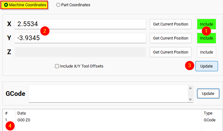
When adding a new position, choose Machine Coordinates or Part Coordinates at the top.
-
To change an existing position, select it and edit as needed.
-
Each position builds a movement list in the Data Box. Use Delete to remove a movement.
- To add a custom G-code line, write it and click Add to include it in the Goto list.
⚠️ Do not use M Codes here.
This helps move the tool safely before other operations.

Add Movement Instructions
-
Click Include for each axis you want to move.
-
Click Get Current Position to copy the current coordinates, or type the coordinates manually.
-
Click Add/Update to save the movement in the Data Section.
Example: Z-Axis Movement
-
Define the Z-axis movement to run first.
-
Click Add/Update to insert this movement into the Data Box.
-
Add more actions in the next rows.
-
Optionally, add a final Z Rapid Move to bring the tool close to the setter.


I modified the Tool Setter position. Coordinate lines in the Data box will be in Machine Coordinates. This will be used as the Tool Setter position and can be called using the P2 variable.
Spindle Settings
These are the settings for the most commonly used Spindle features.
- Pull down Configure -> Control -> Settings tab
- Click the
 button to flatten the full settings tree, then expand the Spindle section


Gear shifter
Before configuring the gear shifter, you need to configure your gear ranges. Use this portion of the Spindle Calibration document for gear range configuration. Set MaxRPM values for each gear
The default settings will work for a machine with a manual gear shifter.
You may use M-codes to run the gear change cycle during a job. M40 - M45 change ranges from 0 to 5. M40 P# can also be used where # is the gear range to use
Load
Connect your encoder to an analog input and map the Spindle Load Meter Register to that input
Orient
MachPro uses M19 to run the orient sequence.
The two primary ways to use it are in Manual or Automatic mode
For Manual mode, the default configuration will work without any changes
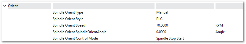
For Automatic mode configure:
- Spindle Orient Type Auto
- Spindle Orient Style Macro
- Spindle Orient Output
- Spindle Orient Input

You may change the other parameters according to what your system needs.
Sub Spindle
The minimum settings that need to be configured for the subspindle are:
- Sub Spindle Enabled
- Sub Spindle CW output
- Sub Spindle CCW output
- Sub Spindle Max RPM

Use M-codes to control the sub spindle
- M013 CW start
- M104 CCW start
- M105 stop
Additional Information
For information about MachPro Software Operation please see the MachPro Mill/Router Operating Manual
| http://www.mach-labs.com | MachLabs Documentation | support@mach-labs.com |
The MachLabs Team
14518 County Road 7240, Newburg, MO 65550
support@mach-labs.com