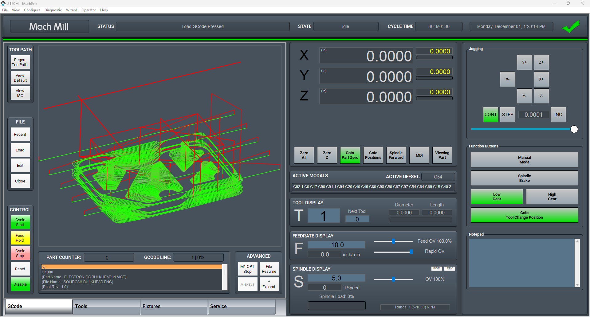
MachPro Mill and Router Setup Manual
![]()
Configure Software
There are two options for setting up units and soft limits. Typically, the easiest way is to use the MachPro Knee Mill Setup Wizard. For more complex configurations, or customization, please refer to the M31 Motion Control Setup Manual
Knee Mill Setup Wizard
Select the Kneemill Setup Wizard from the Configure drop down on the main menu. This will guide you through an initial setup process that will allow you to set axis unit calibration, soft limits, and spindle calibration. You can also go through each step manually by following the information on completing the set up process for Units Calibration and Soft Limits outlined below.

Upon selecting the Kneemill Setup Wizard, you will be presented with a selection of configuration options. Yellow triangles indicate which features have not been completed yet, and green check marks correspond to previously completed items. It is suggested to do the items in the following order:
- Units
- Softlimits
- Spindle Calibration
- Backlash

Units Calibration
To set the units for each axis, the pitch of the ballscrew, the number of teeth on the ballscrew pulley, and the number of teeth on the motor pulley must be known. An advanced option is available for other systems of motion or if the data is not known.
The wizard will go through each axis individually in order (X, Y, Z). For each axis, you must enter the three pieces of data. Every time you change the data, the new units will be calculated and applied to the axis. To verify the units, a 1" dial indicator can be used. The wizard supplies options to move the axis back and forth distances up to an inch. Otherwise, verification can be done by manually jogging or commanding MDI motion.

Soft limits
It is suggested to go through this part with the machine disabled and to use the handwheels to move the machine. It is possible to move the machine with the jog functionality or pendant if the speed is turned down and caution is used.
Use extreme caution when jogging the machine. Until the soft limits are set it is possible to run an axis to its hard limit.
The softlimits wizard will go through the three axes in order (X, Y, Z) and ask you to move the machine first to maximum travel and then to minimum travel. The positions should be within machine physical limits and within any limit switches on the machine, but should encompass most of the usable machine.

For each position, you will either need to select Set Softlimit or Skip in order to proceed. As you move through the wizard, the image will change to help you visualize the correct positions. When you set the maximum softlimits for each machine, the control will set your Home position to the same place, unless the machine has previously been homed.
For reference, while facing the machine, X maximum travel is with the table all the way to the left and the spindle nose all the way to the right of the table. Y maximum travel is with the table as close to the operator as it can go and the spindle nose near the far edge of the table.
After exiting the wizard, limits will be activated. It is now possible to enable the machine and jog the axes into their limits. When the limit is reached, the machine will cease moving in that direction. It is a good idea to turn down the jog rate and test the limits at this point.
Use extreme caution while testing limits in the event that an axis was accidentally skipped or set at an incorrect position.
Backlash
Backlash is caused by the gaps between moving parts such as gears and ballscrews. It is the amount of movement one component can make in one direction without causing motion in the next connected part. Most mechanical systems have some backlash - even when new. If the mechanics are too tight, binding and excessive wear will result. As the gears and ballscrews wear, the backlash will increase, and accuracy will decrease. Ongoing testing and maintenance of your mechanical system is required to minimize backlash.
The M31 provides software backlash compensation as a short-term solution for small, stable amounts of backlash. To calculate the backlash of an axis use How To Test For Backlash
In the case that you have less then .0005" of backlash, this step may be skipped. Backlash compensation will not completely compensate for all mechanical deficiencies.
Be sure to start this wizard with each axis near the middle of travel. The machine needs minimum of 1" of travel in all directions for this wizard to succeed.
The wizard supplies buttons for moving the machine positive and negative 1 inch, input for the amount of error, and an indication of direction of error.

For each axis, move the axis negative and then attach a dial indicator and zero it. Then move the axis positive once. Input the error from the indicator and select the direction of error. Then select Calculate & Apply. Verify the backlash by repeating the process until the machine is consistent.
VFD Setup
Your Variable Frequency Drive will need to be configured for your spindle motor. Please refer to the manufacture's documentation for both the VFD and spindle motor. The VFD will have a way to view and change parameters through the face of the drive, and there may also be software that you can run and connect to the VFD through a USB cable.
You can find out what parameters need to be changed by looking at the info on your spindle motor name plate. Check and change any of the values that need it (Number of poles, wattage, amperage, etc.) to make sure your spindle runs at peak performance.

Spindle Calibration
The spindle calibration wizard requires you to read the specifications from the spindle and insert them into the wizard. The information needed is the maximum RPM for low gear, the maximum RPM for high gear, and the amps for full load. These should be input and then Save selected.
The spindle can be tested by inputting a spindle speed on the screen and then pressing the Spindle FWD or Spindle REV buttons on the panel. If the spindle is turning the incorrect direction, the Reverse spindle direction check in the wizard can be toggled. Be sure to select Save.

If you want to calibrate your spindle with a tachometer, please see the VFD - Spindle Calibration documentation.
Manual Setup
Units Calibration
Before the machine is homed or any further setup is completed we must calculate our steps per/unit and calibrate the motors accordingly. There is both an automatic process and a manual process: 2.4 Axis Calibration
Homing
With the motor units calibrated, we can now set the machine zero and set up the software limits.
Machine zero is used by the control for all movement calculations, but you will not typically use it directly. Your RPKM system has absolute encoders that maintain the position of each axis even when the machine is powered down. We will set the machine zero here once and you will not need to home your mill when you start it up.

- Go to your service tab. Turn off soft limits, enable and ensure that your axis labels are flashing red and yellow. If not, please contact MachLabs for assistance de-referencing your axes.

- Carefully jog X to the most negative location that you want to use (the soft limit location), and then jog positive approximately one inch, where the X machine zero will be set.
- Repeat that process for the Y axis.
- Carefully jog Z up to the most highest location that you want to use (the soft limit location), and then jog down approximately one inch, where the Z machine zero will be set.
- Navigate to the Service Tab and click Home All. This sets the machine zero for all axes. If the Home All button is not active, please contact MachLabs and we will help you de-reference all axes so that you can set your machine zero.

Soft Limits
Next we need to set up the soft limits to prevent crashes. On the upper left hand side of the screen pull down Configure and then Config Soft Limits.
Follow the prompts listed. Soft limit set up can be done on all axes at the same time, or one axis at a time. Continue until all axes are complete. Carefully test each axis to make sure that it will not go past the position you set for its soft limit.
Backlash
Backlash is caused by the gaps between moving parts such as gears and ballscrews. It is the amount of movement one component can make in one direction without causing motion in the next connected part. Most mechanical systems have some backlash - even when new. If the mechanics are too tight, binding will cause excessive wear. As the gears and ballscrews wear normally, the backlash will increase, and accuracy will decrease. Ongoing testing and maintenance of your mechanical system is required to minimize backlash.
The M31 provides software backlash compensation as a short-term solution for small, stable amounts of backlash. To calculate the backlash of an axis use How To Test For Backlash.
To manually adjust the software compensation for backlash, use these instructions: Backlash Repair and Compensation. Backlash compensation can not completely compensate for all mechanical backlash.
In the case that you have less then .0005" of backlash, this step may be skipped.
Lube System Setup
If your system has an oiler edit the lube settings. Pull down Configure -> Control, and select the Settings Tab. Scroll down to the Lube System settings. Enable the lube system, and adjust the settings. In the default settings, the oiler will only run while the control is enabled, and it will run for 8 seconds, then turn off for 5 minutes. Adjust the values according to your machine's needs. Note that lube pumps vary widely in their output. Start conservatively and increase the values to achieve proper lubrication.

Tool Setters and Offsets
Open the Calibrate Tool Setters window. Found on the Tools tab.

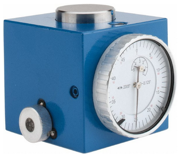
Creating a Manual Tool Setter
Mapping the input to a software signal
Pull down Configure -> Control and select the Input Signals tab.
Some signals are pre-configured when MachPro is installed.
Tool Setter Limit (Over Travel) maybe be mapped to Input #6
Tool Setter Input may be mapped to Probe1.
|
|
|
|


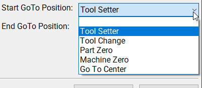
GoTo Position
-
If the tool setter is permanently mounted, then define a GoTo Position so the spindle can safely move to the tool setter before touch-off.
-
This ensures a consistent and safe approach, reducing the risk of collisions.
1. Add or Edit a tool setter
-
In the Tool Setter tab, click Add New to create a new tool setter.
-
Enter a unique name for the tool setter.
-
Select the new tool setter from the list to display its settings on the right side.
2. Setter Type
-
Under Setter Type, select Manual.
3. Tool Setter Height
- This is used with randomly placed tool setters to determine the Z fixture offset. If you have a fixed position tool setter, leave this value at 0.0
-
Measure the physical height of the tool setter.
-
Enter the measured value in the Tool Setter Height field.
4. Z Position
-
For a fixed positionsetter:
-
Use the Z Position Wizard to determine the machine coordinate for the top surface of the setter.
-
Once set correctly, this value should not be changed.
-
-
If the setter is mounted outside the soft limits, enable Disable Softlimits.
- Once the Z position and height are calibrated, the system will automatically use these values for all tool length offset calculations.
Randomly placed tool setter
-
Set Initial Parameters
-
Set the Z Position to 0.0.
-
Leave all GoTo fields blank.
-
This indicates that the setter position may change between uses.
-
-
Prepare the Spindle
-
Remove all tools from the spindle.
-
If the spindle uses tool holders or collets, insert an empty holder while setting the Z position.
-
-
Position the Tool Setter
-
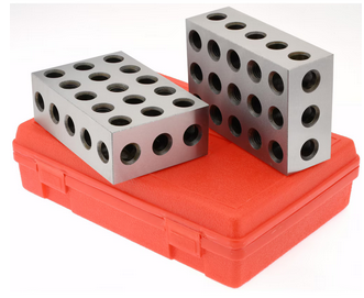
Place the manual tool setter or gauge blocks on the table at the desired location.
-
-
Set the Z Position
-
Carefully jog the spindle down until the tool tip touches the surface of the setter.
-
Click Set Position.
-
This records the Z position using the current spindle location and the entered Tool Setter Height value.
-
-
Measure Tools
-
Insert each tool required for the job.
-
Perform a tool measurement cycle for each tool to record its length offset.
-

Creating an Auto Tool Setter
Click on the Tools tab at the bottom of the MachPro screen, then on the Tool Setters button in the middle of the left side of the screen.
If you are setting up a RapidChangeATC changer and setter, also refer to RapidChangeATB Tool Changer and Tool Setter
|
|
|

- Define GoTo Positions for the tool setter.
-
-
Selecting a GoTo position allows the spindle to move automatically to the setter before touching off.
-
This is recommended for permanently mounted setters.
-
If the setter is located outside the soft limits, enable Disable Softlimits.
-
-
-
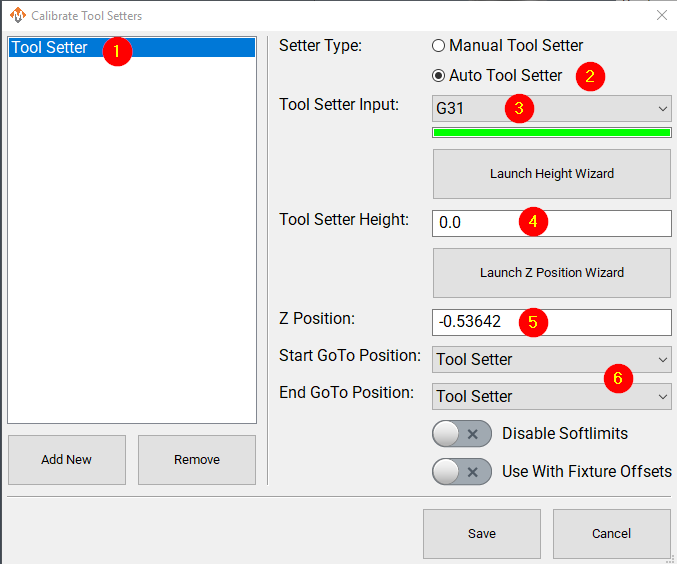
Click Add New to create a new tool setter.
-
Enter an appropriate name for the tool setter.
-
-
Set the Setter Type to Auto.
-
Select the Probe Input that the tool setter is wired to. The 4 input signals available are:
- Probe (G31)
- Probe1 (G31.1)
- Probe2 (G31.2)
- Probe3 (G31.3)
-
If the correct input probe signal has been selected, then indicator bar below the input selector will turn green when the tool setter is triggered. Manually trigger the setter (or have a helper do so) to confirm the correct input is selected.
-
If the tool setter height is known, enter the value in the Tool Setter Height field.
-
If the height is unknown, click Launch Height Wizard and follow the on-screen instructions to measure it.
-
The tool setter must be wired to the control for this process.
-
-
Set the Z Position to the machine coordinate of the surface where the tool setter rests.
-
If the position is unknown, use the Z Position Wizard to determine it.
-
For a randomly placed setter, set the Z Position to 0.0. This value will be defined each time before measuring tools.
-
See also: Using a Randomly Placed Tool Setter.
-
-
For randomly placed setters, leave all GoTo Position fields blank.
-
Manually jog the spindle to the setter or place the setter beneath the spindle as needed.
-
The machine will not perform automatic jogging during this process.
-
Align Tool Edge to Center of Tool Setter
This feature positions the edge of the tool precisely at the center of the tool setter, ensuring accurate alignment and consistent measurement results.
Pull down Configure -> Control and select the Settings Tab. Scroll down to the Measurements and Offsets section.

-
Set Tool Setter Align Tool Edge To Setter to Yes.
-
Configure the Tool Setter Align Tool Edge Offset parameter.
-
Choose between Tool Radius or Tool Setter Offset as the source for the offset used to align the tool edge to the center of the setter.
-
-
Select whether to Align (X or Y) Axis to Setter to define which way the tool moves when aligning the edge to the center of the setter.
- Close the Settings menu
- If you selected Tool Setter Offset, then open the Tool Table and click the Edit option
- Select the User Fields tab
- Select the Tool Setter Offset field, and use the movement buttons to place the field where you want within the User Fields
- Close the Tool Table Editor
- Select View and select User Fields
|
|
|


Additional Settings
The measuring and offsets settings in MachPro Control may provide helpful access to these settings. Pull down Configure -> Control and select the Settings Tab and scroll down to the Measuring and Offsets portion.

Modifying GoTo Positions
If you are setting up the GoTo position for a tool setter, jog the tool to the correct position over the tool setter.

Position Setup Instructions
-
Use the Add or Remove buttons at the bottom to manage positions.
-
When adding a new position, choose Machine Coordinates or Part Coordinates at the top.
-
To change an existing position, select it and edit as needed.
-
Each position builds a movement list in the Data Box. Use Delete to remove a movement.
- To add a custom G-code line, write it and click Add to include it in the Goto list.
⚠️ Do not use M Codes here.
This helps move the tool safely before other operations.

Add Movement Instructions
-
Click Include for each axis you want to move.
-
Click Get Current Position to copy the current coordinates, or type the coordinates manually.
-
Click Add/Update to save the movement in the Data Section.
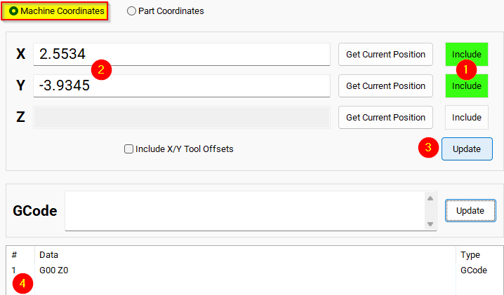
Example: Z-Axis Movement
-
Define the Z-axis movement to run first.
-
Click Add/Update to insert this movement into the Data Box.
-
Add more actions in the next rows.
-
Optionally, add a final Z Rapid Move to bring the tool close to the setter.


I modified the Tool Setter position. Coordinate lines in the Data box will be in Machine Coordinates. This will be used as the Tool Setter position and can be called using the P2 variable.
Additional Information
For information about MachPro Software Operation please see the MachPro Mill/Router Operating Manual
| http://www.mach-labs.com | MachLabs Documentation | support@mach-labs.com |
The MachLabs Team
14518 County Road 7240, Newburg, MO 65550
support@mach-labs.com