MachMotion Probing Wizard
Overview
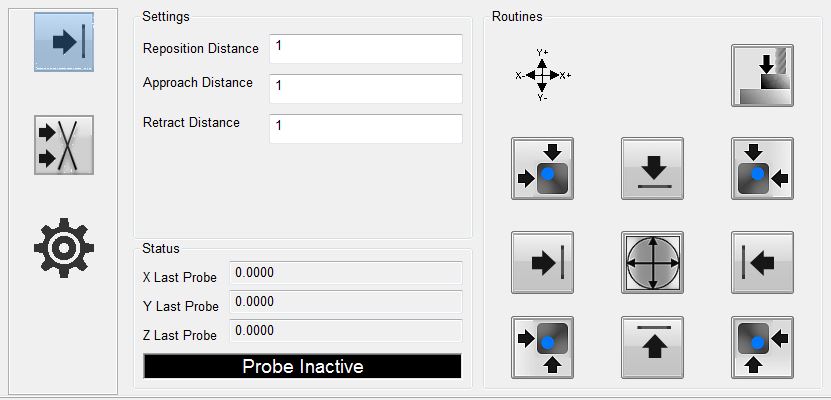
The wizard is embedded in the MachMotion Mill 1150M – Probing screen, but it can be accessed through any screen, by selecting it from the available wizards. The full wizard is shown below. On the left side is a set of parameters that are used to define the distances and feedrates for the probing operations. In the middle section is feedback about current positions and the probe signal. On the right- hand side are the buttons to activate a probing cycle.
General Settings
There are six generic parameters and two parameters specific to setting an angle through G68. All probing operations will use a two-touch system. The probe will approach the part quickly at first, then back up, then touch the part again slowly for a more accurate reading, then back up a final time. After the last retract, it will set the appropriate fixture offset (unless probing for an angle). Nearly all movements are done as probe commands, so that if the probe moves in an unexpected direction it will stop if encounters anything in its path.
Probe Feed Rate: This is the feed rate that the probe will use for the second, accurate touch. It is required to be positive.
Retract Distance: This is the distance that the probe will retract from the part after the second touch.
Approach Feed Rate: This is the feed rate that the probe will use for the first, rapid touch. It is required to be positive.
Approach Distance: This is the distance that the probe will travel to find the part edge. If the probe is not activated by the end of the travel distance, it means that the probe was too far away from the part for the specified distance. You should either start closer to the part or tell it a longer approach distance.
Probe Diameter: This is the diameter of the probe stylus being used. This must be an accurate number in order to get an accurate fixture offset. Further, this diameter is used to determine how far to back up from the part between the first and second touch of the probe.
Probe Code Options: The user can specify which probe signal to watch for while running a probe operation. In Mach, G31 corresponds to the “Probe” input signal, G31.1 is the “Probe 1” input signal, G31.2 is the “Probe 2” input signal, and G31.3 is the “Probe 3” input signal. The probe must be wired and mapped correctly to the selected signal for these operations to work.
Angle Settings
Angles have two methods of being measured. For small pieces with no movement interference, there are four canned functionalities. These options will probe the side of the part (with two touches), then move a specified distance down, and probe the side again. If the part is large or the user wants more control over measuring the angle, they can enter Jog Mode. Once they activate this mode, they can probe a side (which will do two touches), then jog the machine to a new position, and probe the side again. This is useful to expedite travel from one end of a part to another.
Angle Measure Options: There are five options for the user to choose from here. This selection will determine how the machine operates during an angle probing operation.
X--: The probe will move in the negative X direction. This means it will be touching the east side of the part.
X++: The probe will move in the positive X direction. This means that it will be touching the west side of the part.
Y--: The probe will move in the negative Y direction. This means it will be touching the north side of the part.
Y++: The probe will move in the positive Y direction. This means it will be touching the south side of the part.
Jog Mode: The probe will move in the direction that the user chooses later.
Travel Distance: This is the distance that the probe will move between the two probing operations of an angle probe. It can be positive or negative. It is only used when not in Jog Mode.
Status
There are three sections to the Status column. The first section shows the current position of the X, Y, and Z axes. This will be machine or part position, depending on their selection on the main screen.
Obviously, this is more useful when the wizard is not embedded in the screen. The section below that holds the values from the last probe operation of the X, Y, and Z axes. The last section is an LED that indicates if the currently selected probe is active or not. If in the settings, the user has G31 selected,
then the LED will correspond to the input signal “Probe”. If they have selected G31.1, then the LED will
indicated that status of the input signal “Probe 1”. The LED will mark the state of the input signal “Probe
2” if the user has selected G31.2 in the settings, and the LED will correlate with the “Probe 3” input signal if the user selected G31.3.
Functions
There are eleven functions that the probing wizard can do. There are four operations that find a single edge of the part, there are four operations that find a corner of the part, there is one operation to find the center of a circle, there is one operation to find the top (Z axis), and there is one operation to find the angle of a part.
When commanding any probe motions, be sure that your ‘Probe Code Options’ field is set to the correct probe.
Edge Finder
the ‘Retract Distance’ field, and then zero the part.
Corner Finder
Next, it will move in the positive Y axis the distance specified in your ‘Approach Distance’ field. It is important that the distance is correct in order to properly be clear of the part.
After this move, Z will descend the same approach distance. Once the Z has been lowered, the probe will move in the negative Y direction and probe the top edge of the part. This is the same routine as the corresponding edge finder. After probing Y, the Y axis will be zeroed and the Z will raise up. The Y axis will return back to its starting position, over the part. Then X axis will move in the negative X direction the approach distance so that it will be clear of the part. The Z will again descend the same approach distance. At this point, the X axis will perform a full probe routine in the positive X direction. After probing the X edge and setting the zero, the Z axis will raise up, the both X and Y will move to zero. At the end of the routine, X and Y will be at zero and the Z axis will be at the retract distance away from its zero point.
After this move, Z will descend the same approach distance. Once the Z has been lowered, the probe will move in the negative Y direction and probe the top edge of the part. This is the same routine as the corresponding edge finder. After probing Y, the Y axis will be zeroed and the Z will raise up. The Y axis will return back to its starting position, over the part. Then X axis will move in the positive X direction the approach distance so that it will be clear of the part. The Z will again descend the same approach distance. At this point, the X axis will perform a full probe routine in the negative X direction. After probing the X edge and setting the zero, the Z axis will raise up, the both X and Y will move to zero. At the end of the routine, X and Y will be at zero and the Z axis will be at the retract distance away from its zero point.
‘Approach Distance’ field. It is important that the distance is correct in order to properly be clear of the part. After this move, Z will descend the same approach distance. Once the Z has been lowered, the probe will move in the positive Y direction and probe the bottom edge of the part. This is the same routine as the corresponding edge finder. After probing Y, the Y axis will be zeroed and the Z will raise up. The Y axis will return back to its starting position, over the part. Then X axis will move in the negative X direction the approach distance so that it will be clear of the part. The Z will again descend the same approach distance. At this point, the X axis will perform a full probe routine in the positive X direction. After probing the X edge and setting the zero, the Z axis will raise up, the both X and Y will move to zero. At the end of the routine, X and Y will be at zero and the Z axis will be at the retract distance away from its zero point.
‘Approach Distance’ field. It is important that the distance is correct in order to properly be clear of the part. After this move, Z will descend the same approach distance. Once the Z has been lowered, the probe will move in the positive Y direction and probe the bottom edge of the part. This is the same routine as the corresponding edge finder. After probing Y, the Y axis will be zeroed and the Z will raise up. The Y axis will return back to its starting position, over the part. Then X axis will move in the
positive X direction the approach distance so that it will be clear of the part. The Z will again descend the same approach distance. At this point, the X axis will perform a full probe routine in the negative X direction. After probing the X edge and setting the zero, the Z axis will raise up, the both X and Y will move to zero. At the end of the routine, X and Y will be at zero and the Z axis will be at the retract distance away from its zero point.
Circle Center
This function will find the center of a circle and zero there. It will only work with holes, not posts. The probe must start already lowered into the hole. The probe will first move in the negative X direction and probe the side of the circle, and then return to its starting position. All probe operations will do two full touches of the part. After the first edge, the
probe will then probe in the positive X direction, then return to the starting position. You should be sure the approach distance will reach both sides of the circle. After the second X axis probe, the operation will be repeated in the Y axis. The probe will first move in the positive Y direction and probe an edge of the circle and return to start. Then the probe will move in the negative Y direction and find the edge there. At this point, the machine will calculate the center of the circle, and move to position. Upon arrival, it will zero both the X and Y axes.
Zero Z Axis
This function will probe the part in the negative Z direction. The Z axis will move up to the approach distance while trying to find the part top. After the first touch, at the approach speed, the probe will retract a distance based on the probe diameter. Then it will touch the part top again, this time at the slower probe speed. After finding the top of the part, the
probe will zero its position and retract the specified retract distance.
Measure Angle
There are five methods to measure the angle that a part sits at. You can probe using one of the four canned probing functions or you can manually probe the angle using Jog Mode. Each function requires two probe routines to complete. The probe will touch the side once, move a certain distance, and then touch the side again. The canned functions also use the ‘Travel Distance’ parameter. This parameter specifies both direction and distance between the two probe operations. If it is positive, then the probe will move in a positive direction up the side of the part before doing the next probing operation. If it is negative, then the probe will move in a negative direction down the side of the part before doing the next probing operation.
The first function will move the probe in the positive X direction, thereby probing the left edge of the part. The probe will do one full two-touch probe operation against the side of the part. Then it will retract. After retracting, it will move the Y axis the distance specified
in the ‘Travel Distance’ field. For instance, it ‘Travel Distance’ is set to 1, then the Y axis will move positive 1 unit (inches or millimeters). If ‘Travel Distance’ is set to -1, then the Y axis will move 1
unit in the negative direction. After this move, there will be a second probe operation in the positive X direction. When it is complete, the probe will retract from the part and set the appropriate angle.
The second function will move the probe in the negative X direction, thereby probing the right edge of the part. The probe will do one full two-touch probe operation against the side of the part. Then it will retract. After retracting, it will move the Y axis the distance specified in the ‘Travel Distance’ field. For instance, it ‘Travel Distance’ is set to 1, then the
Y axis will move positive 1 unit (inches or millimeters). If ‘Travel Distance’ is set to -1, then the Y axis will move 1 unit in the negative direction. After this move, there will be a second probe operation in the negative X direction. When it is complete, the probe will retract from the part and set the appropriate angle.
The third function will move the probe in the positive Y direction, thereby probing the bottom edge of the part. The probe will do one full two-touch probe operation against the side of the part. Then it will retract. After retracting, it will move the X axis the distance specified in the ‘Travel Distance’ field. For instance, it ‘Travel Distance’ is set to 1, then the
X axis will move positive 1 unit (inches or millimeters). If ‘Travel Distance’ is set to -1, then the X axis will move 1 unit in the negative direction. After this move, there will be a second probe operation in the positive Y direction. When it is complete, the probe will retract from the part and set the appropriate angle.
The fourth function will move the probe in the negative Y direction, thereby probing the top edge of the part. The probe will do one full two-touch probe operation against the side of the part. Then it will retract. After retracting, it will move the X axis the distance
specified in the ‘Travel Distance’ field. For instance, it ‘Travel Distance’ is set to 1, then the X axis will move positive 1 unit (inches or millimeters). If ‘Travel Distance’ is set to -1, then the X axis will move 1 unit in the negative direction. After this move, there will be a second probe operation in the negative Y direction. When it is complete, the probe will retract from the part and set the appropriate angle.
Using Jog Mode allows the user to fully select where to probe the part for both positions. To activate it, select ‘Jog Mode’ from the Measure Angle Options, the press the angle button. It will be green while Jog Mode is active. To cancel Jog Mode, which will discard any points it has probed, press the button again to return it to its normal state. While Jog Mode is active, the
user can jog to any position around the part and probe it using one of the four standard edge finding probe operations. The selected function will perform the same routine that it would under normal conditions, completing a full
two-touch probe routine. After the routine is completed, the user is free to jog the machine wherever they desire in order to probe again. The only restriction is that both probe operations must be of the same type (i.e. probing positive X and then negative Y is not allowed). After two probe positions have been collected, the angle will be set appropriately and Jog Mode will turn itself off.