Alexsys V4 Turn Operator Manual
{{@672}}
Overview
ALEXSYS is a programming system for CNC machining centers. That combines features of CAD / CAM systems with typical features of conversational programming.
It is not necessary to be experienced with CAD/CAM systems to use this software.

Alexsys
The Featureslathe
Thismodule featuressupport belowall arethe inmost everycommon Alexsysturning package.operations.
ImportFacefrom DXF/DWGTurningGenerateExternalGCode/ Internal Turning- External / Internal / Face Grooving
- Central Drilling
CADExternalEditor/ Internal Threading , also tapered threadsToolpath SimulationG-Code CustomizationThread Tables3D Stock PreviewIntegrated calculatorAdvanced profile selectionTimelineManual G-Code InputStock MaterialsCut-Off
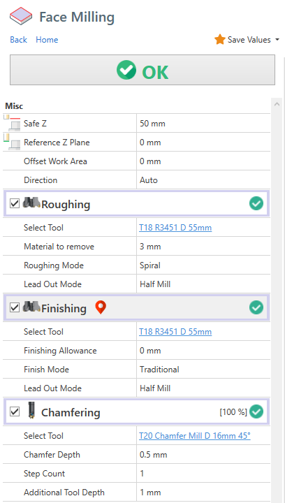
Face Milling
Turning
Safe
Diameter Mode - Auto : Start and end diameter value are defined by stock dimension
Diameter Mode - Manual Values : Start and end diameter value are defined manually
Start Z : It'sReference the z coordinate where the tool is safeZ , whereusually itit's can'talways collide0
Corner anythingMode (: fixtureChoose ,between stockchamfer ,or ..)fillet
ReferenceInit Z PlaneChamfer : IsIt the referencechamfer/fillet z coordinate. Usually it's the zero part Z0
Parallel strategy ( traditional ) :
Direction Auto : The direction is calculated automatically
Direction Horizontal : The direction is parallel to X axis
Direction Vertical : The direction is parallel to Y axis
Child operations availableoperations:
1) Roughing Operation
It process multiple passes in z direction to remove all the material to remove.
The passes depth is determined by the tool cutting data parameter. ( Max Cut Height )
Material to remove : MeasuredIs the material width to remove , measure from ReferenceStart Z Plane to Z+ direction
RoughingFinishing Modeallowance : It'sIs the selectedmaterial strategywidth left to finishing operation by the roughing operation
2) Finishing Operation
ItNo performoptions for this operation.
Generic Turning
External Cycle : The tool moves from the lastoutside finishthe passinner part of the component.

Internal cycle : The tool moves from the inner part of the component to outside.
Before proceed with internal cycle is necessary create a central hole in the component.
In important also use a tool with dimension compatible with this hole diameter.
You can find this information in tool catalog.

To add this operation, from [MENU] -> Lathe -> External or Internal Turning , depending on your needs.

Here the partscreen face.related to external / internal turning machining.

Geometry Selection
Generic turning accept as geometry both open profiles and closed profiles.
It's suggested to link just a single profile in geometry list.
Open Profile:

Closed Profile:

Turning Parameters
Turning direction - Traditional : Tool direction it's from Z+ to Z-
FinishingTurning allowancedirection - Reverse : Tool direction it's from Z- to Z+ , you need to select a compatible tool when you change this property.
Profile Start/End Extension : A tangent extension will be added to start/end of selected geometries
Apply Fillet on sharp corner : Where applicable, a fillet will be created in sharp corner.
Toolpath Limit : With this you can define the limits of working area.
Without Limit :

With Limit :

Operation 1 of 2 : Roughing
Finish Allowance X / Z : It's the material thickness left by the roughing operationtool for the finishing operation.
3)
Roughing ChamferingMacro
Where applicable , it will print G71 macro code in output code instead of simple movementsContour:
Finish with same tool : Finishing allowance material will be removed by the roughing tool
Operation 2 of 2 : Finishing
Reverse direction on vertical wall : When enable , the turning direction will be inverted in 90° profile element. In some context , this may reduce tool vibration.
Vertical wall threshold : Will be considered only elements with length bigger than this value.
Multiple finishing passes : It create multiple finishing passes. The distance between passes is determined by finishing allowance thickness.
example : If you have a 0.3mm of finish allowance and 3 finish passes. Toolpath will generate 3 passes with a 0.1mm distance between them.
Lathe Central Drilling
To add a drilling machining , from Menu -> Lathe -> Central Drilling
This is the machining property screen.

Here you can find Contour and Pocket operations.enable these sub-operations :
- Center Drill
- Drill
- Chamfer
- Tap
- Reamer
You can change the sub operation order manually from treeview. See related link at the bottom of this article.
When a drilling operation is selected, is possible see also "ghost tool model" at the minimum reached z.
This 2is machininguseful operationsto are identical exceptcheck the facttool ,path bycorrectness defaultat , contour will work the outer area of selected profiles, and pocket will work the inner area of selected profiles.glance.

Switch profile side
Is possible switch the side of selected geometry.
You can both click on the double sided arrow in geometry list box or click the yellow arrow in viewpoint . When you hover the yellow arrow with mouse cursor , the arrow will turn red. Click on it to change working side.
The highlighted area in viewpoint , will be the area machined away by the operation.


Open Profiles
Contour and Pocket operations need a closed profile to work with.
If you select an open profile instead, Alexsys will try to close it with the outer stock profile.
See image.
Also in this case you can switch working side .
Z Levels
Safe Z : isIt's the Z PlaneLevel whereof theapproach . The tool approacharrives at this level in rapid movementrapid.
Start Z : IsThis is the z plane where the tooleffective start removeworking materiallevel. Usually it's 0
Depth[Drill Operation] Add Drill Tip Length : It Iscalculate the thicknessdrill oftool materialtip length and add it to beinserted removed , measured from Start Z
By default these values are applied to all associated geometries.
But if you enable the "depth. DEFINE Z LEVELS FOR GEOMETRY" , these value are applied only to current geometry. The current geometry is highlighted with red strokes in viewpoint and active in geometry list box

Groove Width
With a 0 value in WIDTH property , the region area is filled .Like this

But if i set a value in WIDTH the working area is created by offseting the source profile , like this.

This property is set just to the selected profile in geometry list box.
Overhang
Overhang feature is useful to create the side slots with this tool.

You need to enable [Is Overhang Active] and set the [Slot Height]
The bottomdrill parttip of the slotlength is determinedcalculated by the [Starttool Z] and [Depth] values.diameter Theand Slottool height is measured from the bottom part to Z+ direction.

By default , the outer overhang area is defined by the stock outer contour.
Roughing plunge points
To force plunge point position for roughing operation, enable "Select Plunge Point" to pick to position with mouse.
Use [Clear Points Selection] to remove all defined plunge points.
Finishing Start Points
Is also possible define finishing start points. Use [Define starting points] under finishing operation.below.

Use [Clear Points Selection] to remove all defined plunge points.
Keep Tool Down
By default, after every pass in Z direction, the tool move to [SafeChamfer] Z]Define Chamfer Diameter : level . The reason is to keep the maximum safety in toolpath creation.
But if you see there is no issue with stock collision, you can enable [Keep Tool Down] . In this way the tool goes directly to next z level , without moving to [Safe Z] after every pass.
You have 2 different [Keep Tool Down] options, one under roughing operation and one under finishing operation. So you can have active in one operation and disabled in the other.

Finishing Offset
Is possible apply a negative or positive offset value to profile. With this you can remove more or less material from stock with finishing tool.

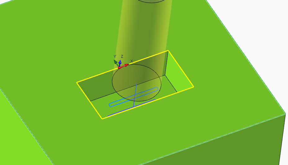
Override Geometries
In this image, only a square is defined in geometry selection box. The stock profile is defined by the stock setup. The toolpath is calculated in order to remove all the material from stock until it reach the defined profile.

Is possible override stock profile by :
Adding a new entity to geometry selection, in this case a circleSetting it as [Stock Profile] from the dropdown menu.


With the new stock profile defined , the toolpath in calculated in order to remove just the material from custom stock profile.

Trim By Stock
Let's say this is your current stock model.

Then you need to machine a squared shape . By default this is the generated toolpath. You clearly notice the tool is working on already machined area. The toolpath is not optimal.
 You can enable
 [Trim toolpath by current stock] .

The toolpath engine will calculate the stock model resulting from previous operations, and will use that model to skip the already machined area.

This will be the optimized toolpath. Now the tool works only where there are material to remove.

The [Trim By Current Stock] feature is computationally expensive.
Where applicable, use the override geometries method, which is more light to process.
Engraving
With ENGRAVING machiningchamfer operation is possible define the plain tool depth to engraveexecute textor anddesired geometries.chamfer outer diameter.
ForIf textyou isselect availableto :define the outer chamfer diameter, the effective tool depth will calculated automatically based on selected chamfer tool geometry.
SingleThreadingLineTo
fontadd TrueanTypethreadingfontmachiningtypeoperation ,withfromanyMENUfont->familyLATHEinstalled->onselectPC.EXTERNAL
Lathe

In the screen below you can see requested parameter.

You can define text on circular or linear pattern, mirrored around X or Y axis and you can apply many alignment options.
And of course all the selected geometry can be engraved.

Cut Operation
This is the machining you need to use when you want cut 2D Profile from material sheet.
Just select the geometries of the profile you want to cut.
Select the relative position of the tool :
InternalCentralExternal


Holding tabs
Holding tabs are needed in order to keep your cut part stable after the machining.
In this way the machine or tool are not damaged.
You need to manually remove the cut part from sheet
.
Check the property ADD HOLDING TABS.
To create this holding tabs, the tool need to raise in some points.
You have to define the thickness and length of this holding tabs.
To define the position you can proceed manually or use the automatic method.
Automatic Mode
With automatic method, you need to define how many holding tabs you want to add.
The positions are calculated automatically.
Manual Mode

If you want to set the holding tabs in precise point, you need to select [Manual Mode].
Then click on [Pick Point], and click with mouse in desired points.


Thread Milling

Common parameters
Select Tool : You need to choose apick thread mill tool. In case of internal thread , is necessary a tool diameter a bit smaller than predrill diameter.
Select Thread Category : Choose the thread family from dropdown field
Threading : Select the thread dimension you need. If you need to add a new row or edit some default data ,by openselecting a thread category and then selecting desired thread table and edit related property. To open the thread table you can click on the button at side of this field. Or from menu -> edit -> thread table.
Pitch : It's one of the field that will be defined automatically after choosing thread row. You can edit it manually
External Threading : Check this if you need to create an external threading.
Depth : Thread depth measured from [Start Z] level.
Thread Mode : You can choose between :
Right Handed - ClimbRight Handed - ConventionalLeft Handed - ClimbLeft Handed - Conventional
The suggested working method is Climb
Compensation Mode : See related page for more info.
Step Count : For larger thread , it's better create the thread with multiple axial pass.
First Step % : Available when you select for the one pass to create the thread. It indicated the % of material removedrow from the firstdrop pass.down property.
Internal Thread
After selectionselecting ofdesired threadthread, dimension. All the threadall related propertyfield are filled with default data from thread table.
To open thread table window , you can click on button indicated in following image, or from MENU->EDIT-> THREAD TABLE

Lathe cut-off operation
When is necessary cut away turned part from bar, you need the Cut operation .


Pick Point : Let you select outer diameter and Length with mouse cursor.
Outer Diameter : It's the start diameter of threadcut helix. In case of [Computer] or [Tool Wear] compensation . it will be reduced by tool diameter.cycle
PredrillEnd Diameter : It's used as start approach diameter. The tool will reach touch this diameter and then will approach the helix diameter with a arc tangent movement.
External Thread
After selection of thread dimension. All the thread related property are filled with data from thread table.
External Diameter : It's used as start approach diameter. The tool will reach touch this diameter and then will approach the helix diameter with a arc tangent movement.
Inner Diameter: It's the end diameter of threadcut helix.cycle. InThis casediameter is compensated with tool nose radius in gcode.
Length: It's the desired length of [Computer] or [Tool Wear] compensation . it will be increased by tool diameter.part.

Multi Teeth Tool
From tool geometry screen , is possible define multiple teeth .

The generated toolpath will be compensated in order to use all the teeth, resulting in shorter toolpath.:
Toolpath created with single tooth tool.

Toolpath created with multiple teeth tool.

Adaptive Toolpath Strategy
It's considered a high efficiency because it can easily extend your tool life using a different path compared to the traditional OFFSET strategy.
The tool never work on full load.Tool wear distributed uniformly along the fluteLess power needed from machineIt never exceed tool engagement angle, in this way on the tool is never "overloaded" with material to removeIt's not necessary have particular machines to get benefits of this

This is the common default OFFSET toolpath. In indicated point the tool work almost at full cut and there is a big engagement angle.

This one is the toolpath generated with ADAPTIVE strategy . You can see the tool works with constant load and never exceed a high engagement angle. In this way you can use deeper passes in order to distribute the force all along the flute.

https://www.harveyperformance.com/in-the-loupe/8-ways-youre-killing-your-end-mill/, in particular to section "Using Traditional Roughing"https://www.cnccookbook.com/thinking-about-high-speed-machining-corners-stepover/https://www.cnccookbook.com/high-speed-machining-trochoidal-milling-hsm-speeds-and-feeds
How to change feed value to link moves ?
From version 4.1.0.111
You can edit the default feed in link moves from post processor dialog.
1) Select the Machine Properties tab
2) Search "adaptive"
3) Insert your custom value. Leave 0 to use the fabric default value.

Chamfering Operation
You can find the chamfering operation in almost all the milling machining.
It's used to create a chamfer onor thefillet materialin withcut a tapered tool.corner.
ChamferChip DepthBreaking : It's the dimension of the desired chamfer
Step CountMovement : SometimesWhen it'senabled, preferableit create thea chamferchip withbreaking multiplemovement passes,instead withof thisa propertyplain youwork decidemovement howto passes you need. The tool depths are calculated keeping constantcut the volumepart. of removed material .
Additional tool depth : This property allowhelp to move the tool down in Z- direction , but keeping the same chamfer depth .
Useful if you want to move the contact point away from tool tip.

Tool Diameter Compensation
In Alexsys there are 3 compensation mode available :
Within CNC Mode and Tool Wear Mode , a linear approach movement is automatically added at start and at the end of toolpath.
This is necessary to enable machine tool compensation.
In the output code are visible codes for enabling / disabling cutter compensation (usually G41/G42/G40).
The linear approach movement is 5% larger than the tool diameter.
Computer Mode
This is the most compatible mode, since the final path is calculated automatically. The output code don't contains any command related to compensation ( usually G41 - G42 )
It's not possible adjust the toolpath from the machine tool table. You don't have to worry about setting tool diameter in Tool Diameter register.
It's not indicate if you have to keep tight tolerances in your workpiece.
See info about output code .
Computer Compensation Mode:

CNC Mode
This the least compatible mode. The output path reflect exactly the geometry profile. All the offset distance and effective toolpath are calculated by cnc machine.
With this mode is necessary define tool diameter in cnc machine tool table. Is possible adjust tool wear value in order to compensate possible tool deflection.
The toolpath preview and simulation always show the uncompensated path. This issue can be visually misleading to the user.
The toolpath will be compensated in cnc machine, so there you'll get desired toolpath.
CNC Compensation Mode:

Tool Wear Mode
The offset diameter is calculated by the computer, but you can also adjust the toolpath editing the machine tool wear table .
This permits to have less incompatibility issues with cnc.
Tool Wear Compensation Mode:

Both in CNC Compensation and Tool Wear compensation, if toolpath engine can't create propersmaller lead in / lead out movement, an error is raised.

If this happen, try to reduce the approach radius value , under the finishing operation

Output Code
To help the machinist have clear what compensation is enabled and what values has to insert in cnc tool registry, in the output code are visible all this information.
Both in tool summary and when the tool is actually called.
Computer Compensation Example :
In Tool Summary :
(#7 - END MILL D 8MM COMP COMPUTER - RADIUS COR VALUE 0)
On Tool Called :
N5 (POCKET - FINISHING) (COMP COMPUTER - RADIUS CORRECTOR VALUE 0) (END MILL D 8MM)
CNC Compensation Example :
In Tool Summary :
(#7 - END MILL D 8MM COMP NCCONTROL - RADIUS COR VALUE 4)
On Tool Called :
N5 (POCKET - FINISHING) (COMP NCCONTROL - RADIUS CORRECTOR VALUE 4) (END MILL D 8MM)
Tool Wear Example :
In Tool Summary :
(#7 - END MILL D 8MM COMP TOOLWEAR - RADIUS COR VALUE 0)
On Tool Called :
N5 (POCKET - FINISHING) (COMP TOOLWEAR - RADIUS CORRECTOR VALUE 0) (END MILL D 8MM)
In this way , directly from gcode , you can see what compensation mode is going to be activated , and what value have the machinist have to insert in the machine tool table.
From this comments ,you have to set the tool diameter only with CNC Compensation, with the other two modes you have to set to 0 the tool diameter.
Operations Logical Sort
In home treeview toolbar, is visible the Logical operation sort button.

When enabled , all the operation are keep sorted by logical flow of the machining logic.
So , for example, the centering operation comes before the drilling operation, the drilling operation comes before the tapping operation, the roughing operation comes before the finishing operation and so on.
Advanced Profile Selection
With [Chain Selection] is possible select contiguous entities. Entities be defined contiguous when they have a common endpoint.
But sometimes we need to extract profiles from intersection geometries. See case below.
In this case , it comes useful another kind of profile selection. To add entities to selection you can :
Keep pressed[CTRL]and keep pressed [Mouse Left Button] and hover with cursor toADDto selection group .Keep pressed[CTRL]and single Click on entity with [Mouse Left Button] toADDto selection group .Keep pressed[SHIFT]and keep pressed [Mouse Left Button] and hover with cursor toREMOVEfrom selection group .Keep pressed[SHIFT]and Single Click on entity with [Mouse Left Button] toREMOVEfrom selection group.Press[ESC]to reset current selection


Appendix
Import 2D CAD File
Import DXF/DWG
- You can't import 3D shape
- It's better clean the cad file , leaving only the needed geometry before importing the file.
With Alexsys you can import 2D geometries from DXF / DWG files.
-
First select the plane you want to import the geometries you can select the XY or the XZ planes.
The XZ is the lathe plane.

-
From menu [FILE] -> [OPEN FILE]
Choose the file you want to import.
How to generate G-Code
To Generate G-Code , press this button from main Menu or press F8 from keyboard.

-
This window dialog is the next step , here you can define gcode output filepath.
Press G-Code or keyboard [ENTER] to generate GCode.
After generation the generated machine code will be opened into select text editor.

If may receive this error message :

This means that some operations toolpath are not valid.
Look at tree view you have some operation with error icon.
 Hover with mouse cursor the error icon to read message error.You need to solve all the issue before call g-code generation.
Cad Editor
Alexsys is not indented to be a full CAD system, but with the available tools is possible draw basic profiles or do some little edits to imported geometries.

Toolpath Simulation
Is possible get the simulation of generated toolpath with the command "Simulation"

Here the simulation side screen.
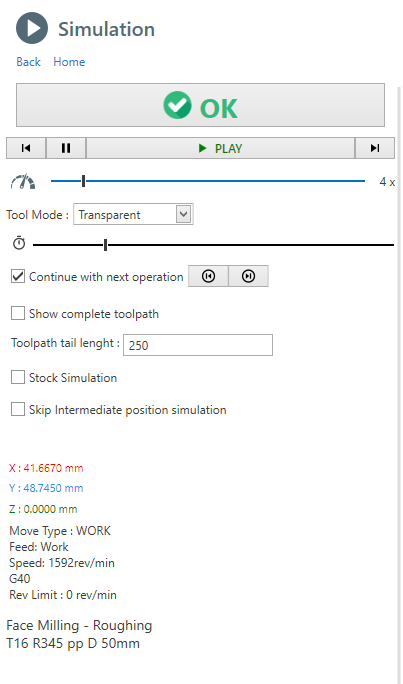
With simulation control you can single-step forward or backward.
Pause and continue simulation

With this control you can increment simulation speed. Drag the cursor with mouse

This slider stand for the current operation timeline, you can drag the cursor forward or backward.

Tool Mode : is possible show the tool with transparency or hide it completely
Continue with next operation : If checked, at the end of an operation simulation, the next operation is played. Otherwise the animation is stopped. Use the 2 button to go to next or previous operation manually.
Show complete toolpath : If checked, all the movements of current operation are shown .By default , just a the last part of the toolpath is visualized . The length of this visualized toolpath is determined by the property "Toolpath length".
Stock Simulation : If checked, the material removal simulation is shown. This option might impact on performance.
Stop on Collision : When a rapid collision is detected, the animation is paused on collision event. This option , is enabled only when the stock simulation is active.
Information : Current tool position and cut data parameter are visible in the lower part of the screen.
To get better performance on a PC with limited hardware you can :
- Disable [Stock Simulation] . Only movements are showed
- Enable [Skip Intermediate Position] . Only movements endpoints are visualized
It's not detected any collision between tool and fixture or tailstock.
Also very high feed work movements into stock are not detected.
Only rapid movements into stock are detected as collision.Basic Concepts
Here a brief explanation to understand the workflow to convert toolpath into gcode.
NC Program stages
You can consider the nc-program as a sequence of stages , each stage has it's own template :
- G-Code Header
- For each operation
- Tool Change
- Tool Approach
- List of movements that make up the toolpath, or in some cases macros (drilling, tapping, etc ..)
- Tool disengagement
- Operation Finalization
- G-Code Footer
For each of these phases it's called a template and a tags dictionary, from the union of these two elements you get the output g-code.
Templates
Here an example of a template , which is nothing more of plain text .
Inside this text , you can see some word between curly brackets. These are the TAGS.
{EMPTY_LINE}
{LINE_N}
({OP_DESC})
{RADIUS_COMP_INFO}
({TOOL_LABEL})
T{TOOL_POS}M6
{NEXT_TOOL_POS}
{FEED_MODE}
S{SPEED_VALUE}{SPINDLE_ORIENTATION}
{ORIGIN}
{COOLANT_CODE}
Tags Dictionary
The tags are the variable values, here an example of a tags dictionary.
LINE_N = N5
TOOL_POS = 15
NEXT_TOOL_POS = 10
FEED_MODE = G98
SPEED_VALUE = 2387
SPEED_ORIENTATION = M3
ORIGIN = G54
COOLANT_CODE= M8
Output Final Code
From the combination of the single template and the tag dictionary, the output g-code will be created.
N5
(CONTOUR - ROUGHING)
(COMP COMPUTER - RADIUS COR VALUE 10)
(R390 D 20MM)
T15M6
T10
G98
S2387M3
G54
M8
...
The tag value will replace the {TAG_WORD} in the template.
Dictionary Convention
To facilitate understanding of the parameters available in the dictionary , it's been used a convention for naming tags.
Suffix _CODE :
These tags values are complete with both the char ( F, G, M) and numeric part ( 100, 0.3)
example :
{FEED_CODE} => F.3
{SPEED_CODE} => S100
Suffix _VALUE :
These tags values contain only the numeric part ( 100, 0.3) .
example:
{FEED_VALUE} => .3
{SPEED_VALUE} => 100
Thread Table
In Alexsys is available also a thread database for the most used thread tables.
This mean you don't need to search diameter or pitch values to create machining operation.
Just select the desired thread item from a list to compile all the necessary data.
To open thread table dialog , from menu click EDIT and then THREAD TABLE


Add custom data
This database can be expanded with custom data.
Open the thread table dialog.
- Select the desired thread family ( category)
- Insert the new values in the last row of the table.
To find reliable thread information , search directly from tool builder website. There you can find more information about everything . Suggested pass count,thread depth and angle , predrill and some useful tips about thread machining.
Edit Pitch
To edit pitch value , simply click on [Pitch Details]
Is possible to edit :
- External Thread Height
- External Passes Count
- Internal Thread Height
- Internal Passes Count
Edit Category
Also the thread category are editable.
Is possible to edit :
- Description
- Unique Id
- Select between TPI and Pitch values
- If is tapered or not
- Taper Angle
This information will be used in code generation.
If you want to hide the a category, check the "HIDE THIS CATEGORY FROM DROPDOWN THREAD LIST" field.
3D Stock Model
In Alexsys the 3D stock is modeled with defined machining operations.
From preference dialog you can choose how the model is created . From Menu -> Edit -> Preferences -> 3D Model Creation Mode
1 ) By Toolpath
The generated 3D model, is the effective result of the toolpath movements.
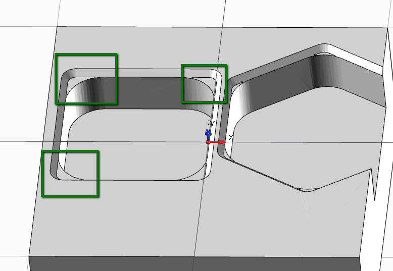
In this way you can see if there something wrong with generated toolpath.
For example, in the case below you can see the material left in the corner from the end mill machining. This is what you get on real machining.
[Simulation Stock Quality] is related to the stock in simulation context.
[Static Stock Quality] is related to the stock modeled in viewpoint context.
2 ) By Work Properties
This generation mode is usually faster , especially for simple 3D model, but it doesn't reflect the effective toolpath.
Some work machining like threading and engraving are not elaborated .
In the example below you can see the model is not considered the corner radius of the pocket. It's just used the profile and work parameter to model the stock.
Textbox integrated calculator
Every numeric textbox has an integrated expression solver.
This mean you can insert expression like " ( 6+6 ) * 2 ", and when you leave the textbox field, in the text box will convert it to 24 as result.

Unit Conversion
Is also possible unit conversion , from [mm] to [inch] and from [inch] o [mm] units.
Just insert [mm] or [in] suffix at te end of inserted value.
Example:
In a [mm] unit file instance, set as text " 1 in " or 1 inch in any numeric textbox .
The value will be converted in 25.4 mm .
Timeline
In the window application bottom , is visible the timeline control.

1) It's the time of current selected operations.
If you hover this label, you can see the timing grouped by setup, if you have multiple setup in your project.

2) Here it's a graphical representation of machining time of each operation.
The purpose of this graphic is too see at glance what operations are taking most of the machining time.
Every operation has a different color, if you hover it with mouse cursor you can see the related operation in the viewpoint.
Click on color bar to select related operation.
Manual Code
With [Manual Code] operation , is possible add manual text in output g-code program.

Load Template : Load existing gcode.
Description : It's the name of current template . It's used as identifier when you need to save , load or delete a template.
Insertion Mode :: Write only g-code : In output gcode related to this operation, you get the imputed text without any other command.
Insertion Mode :: Call Tool + Manual Code : In output g-code related to this operation , you get also the tool change and tool disengagement logic.
Save Template : Save the current text as template. You can find it in template list after this.
Delete Template : It will delete the related template from list.
G-Code Text : It's the manual g.code text you are going to add in output code.
Note : The "manual g.code" operation is just to add plain gcode to output text.
Simulation of this operation is not meant to be good , it will read only linear movements.
Macro , M-Codes , CRC compensation or other commands are not elaborated.
Stock Materials
In Alexsys is possible define several stock materials.
The purpose of having several stock material is to give the possibility to save different tool cut-data for the same tool.
Example :
With the same End-Mill :
-> if you are going to work mild steel , the software will select related cut data parameter for mild steel
otherwise
-> if you are going to work aluminium , the software will select related cut data parameter for aluminium
Default Material List
By default you have 3 material available:
- Mild Steel
- Stainless steel
- Aluminium
To open the material dialog, first you need to open tool table :
From Menu -> Edit -> Tools

then click [EDIT STOCK MATERIALS] from tool table.

The button is available only when you open tool window from menu.
When you open tool window in "Tool Selection Mode" this action it's not enabled
Below the MATERIAL LIST window.

Create New : Add a new material to the list. See below the properties you need to edit.
Delete : It delete permanently selected material. It not suggested delete materials after using it in some project.
Save And Close : Save user edits and close the window
Material Properties
Unique Id : This is an auto-calculated property. It's the combination of [Material Group] and [Material Grade] properties.
1) Is important have a different unique id for each material. This property is used to retrieve the cutting data parameters related to the material.
2) Don't change this id from existing material , since you are going to lose all the referenced cutting data .
Description : This is the description you are going to see in home treeview or in combobox in the tool store dialog.
Material Group : You can consider this as the material main category . The common group are P - M - K - N - S - H
Material Grade : For the same material group you can have different material grades. Insert the value in this field.
Material Group and Grades are used from tool builder to classification the various material of component part.
Here and here , some tools website with more information about this classification.
Specific Weight : Right now this property it's not used from the software. It's planned a method to give to the user the weight of the stock. So it will come in handy in the future.