Turn the "Servo ON"
Select "Start Tuning"
Softwareand will run a series of moves that are preprogramed into the drive. (similar to the inertia test)
2: Position Reference Input This allows you to jog the machine from Mach while autotuning, only attempt this if Option 1 fails repeatedly. (In general system tuning has proved to be a better option.)
Click the Autotuning button.

1: inertia
"0" Will run an inertia calculation again as part of the autotune.
"1" Will skip the inertia calculation: choose this option because we already did it earlier
2: Mode selection
"1" Use this one by default
"2" Use if 1 doesn't yield good results, in the past it's been seen to perform very closely to standard
"3" Use like Option 2
3: Mechanism Selection
Set to match the mechanics of the axis.
"1" Belt mechanism refers to a long flimsy belt running the length of the axis with a pully on either end. (think of a light waterjet)
"2" Ballscrew mechanism should usually be used by us, this will also apply to rack and pinion axis
"3" Rigid Model refers to a weight directly coupled to the motor, (think rotory tool changer without any gearing)
4: Distance
This is how far the motor throughwill go during the tune, usually default is fine. just be on the lookout for astronomical numbers.
5: Defaults?
Always check this on the first tune, only uncheck it if you are trying to stack tunes by picking up were the last one left off. (usually only done in a very high inertia situation)
Click "Next"
Click "Yes"

Click "Servo On"

Click "Start Tuning"
THIS STEP WILL CAUSE MOTION ON THE AXIS! Click "Yes"

Wait for the axis to finish it's pre-programmedpreprogramed moves
- (It might sound like death but that's ok)

Click "Finish"
TheGo driveahead isand tuned
Clickthe "Finish"software againreset toif exityou're only doing one axis, if you're tuning mode
axis If tuning fails it could be caused from one of the following reasons:
The position tolerance is too small. Increase Pn522 to allow for more position error.
Inertia could be too high.
Final Parameter Setup
- Turn off model following by setting Pn140 digit 0 to 0.
- Set feed forward gain Pn109 to 0%. unless you are trying to work around very High inertia, then try 75%
CheckWrite the followinginertia parametersratio into the install binder (Installer only)
If you have a Sigma 5 drive this is your only good option 
If you have sigma 7 drives don't use this section, skip down to "System Tuning".
First, autotune all single motor axis using the methods above.
Then check position error on all axis that driveat the toolsame usually X, Y and Z,IPM. (Exclude things like tool changers).
Pn100 (Speed Loop Gain)
Pn101 (Speed loop integral time constant
Pn102 (Position Loop Gain)
Pickusually the Highestmax value for Pn101 and the lowest for Pn100 and 102 from all axes values.
Then make all included drives match each parameter.
Pn100- Lowest
Pn101- Highest
Pn102- Lowest
System Tuning
Manually Setting Inertia Parameters
On a gantry machine or other arrangement where multiple motors are physically connected together, you can't use a standard inertia tune to calculate moment of inertia.
See the attached date sheets for motor information. SGM7A motors start at Page 75speed of the Sigma-7slowest document.axis) this SGMXAreading motorsshould startbe attaken Pagewith 78the machine performing a sustained feedrate move (not during the accel or decel sections of the Sigma-X document that can be found at this link, it was too large to attach to this document. With some digging, these sheets will give you the "Rotor Moment of Inertia" and "Rated Torque". In the example below we're working with a SGMXA-25A... motor.motion)
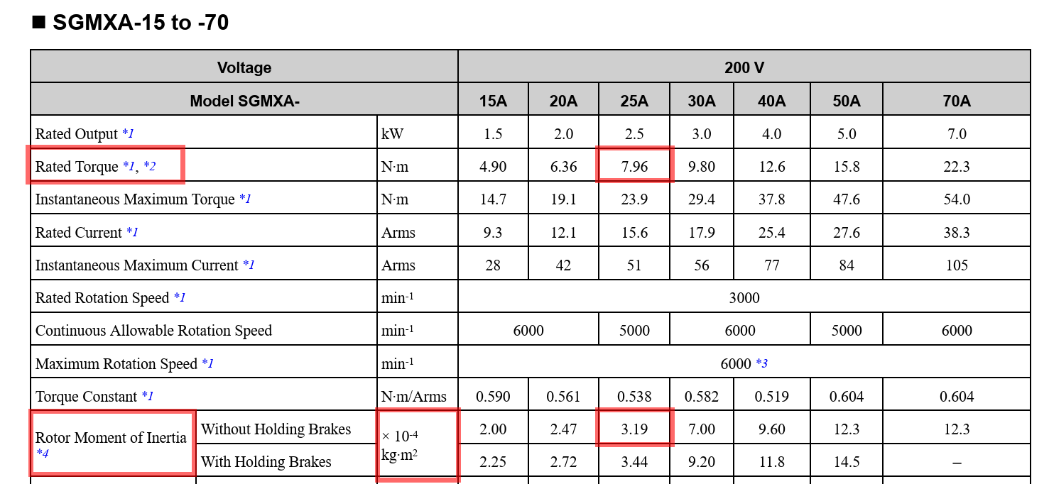

PayConvert attentionfollowing error from counts to theinches exponents. Onusing this motor the inertia is listed in the sheet as units of ×10^4 kg∙m2 so you would enter in =3.19*10^-4
Search the internet for "Sigma II Parameter Calculator"formula or use the calculator in the link (also attached sheet.to the manual)
(Counts Per Unit)/1000 = X
(Position Error) / X = Position error in thou
https://docs.google.com/spreadsheets/d/19xXUOK75FnIN3B1aj_EDSktX5nj8XN5OVXC3Y_g2d-E/edit#gid=0

1:
Input "Counts Per Unit" from "Configure/Control/Motors" (you must do "Machine Calibration" for this axis first )
2:
Input the max position error you observe during a sustained move, (not during the accel or decel sections of motion)
3:
Write this down and compare all the axis
Since you don't have system tuning available on sigma 5 you have to adjust Pn109 to match the position errors however Pn109 tells the drive to add a buffer to it's commanded positions shrinking the following error.
therefore you have to pick the drive with the lowest position error as the standard and then increase Pn109 on the other drives to match. hoping that they don't become too tight and start running poor motion and/or overshoots on corners. (try to stay below 75% )
Position Error in thou is the gold standard, all axis must match at the same IPM to have a well tuned machine
System Tuning (Sigma 7 Drive feature ONLY!)
First, autotune all single motor axis using the methods above.
Then check position error on all axis at the same IPM. (usually the max speed of the slowest axis) this reading should be taken with the machine performing a sustained feedrate move (not during the accel or decel sections of motion)
Convert following error from counts to inches using this formula or use the calculator in the link (also attached to the manual)
(Counts Per Unit)/1000 = X
(Position Error) / X = Position error in thou
https://docs.google.com/spreadsheets/d/19xXUOK75FnIN3B1aj_EDSktX5nj8XN5OVXC3Y_g2d-E/edit#gid=0
1:
Input "Counts Per Unit" from "Configure/Control/Motors" (you must do "Machine Calibration" for this axis first )
2:
Input the max position error you observe during a sustained move, (not during the accel or decel sections of motion)
3:
Write this down and compare all the axis
Position Error in Thou is the gold standard, all axis must match at the same IPM to have a well tuned machine
Pick the Axis with the best result (usually the loosest tune and highest position error) as the standard and adjust all other axis to match.
If you downloadhave enough USB cables and ports connect all your drives at once, If you are tuning a gantry you must at least connect a USB cable to both gantry drives.
They should show up like this with the sheetnames fromyou already gave them

Connect to all of them
Yaskawa recommends setting Pn408.3 to 1 on the internetslave drive of a gantry (needs a bit more testing)
Make sure an inertia ratio is already set
Select "system tuning"

Click "OK"

Navigate
to
theIt Inertiashould Tablook andlike enterthis

Next bring in the inertiaother anddrives ratedby torque fromrepeating the data sheet.
The cells with fill color are expected to be filled by you. Tp, Tf, Δt, ΔV, Motor Rated Torque and Motor's Rotor Inertia. Don't use the Motor model number drop down since it's for Sigma-2.process.
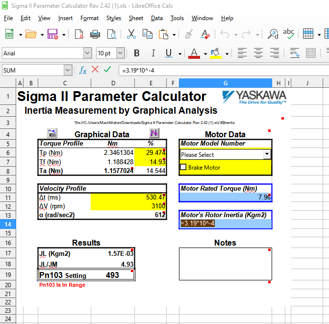

Torque
If tuning a gantry click "Adjust Equally" if no gantry Click "adjust individually"

If you picked "adjust equally" you must select the master Axis as "Base" with the first click and VelocitySlave Profilesaxis willas be"Applicable" gottenwith fromthe asecond
trace
inIt SigmaWin.should look Connectlike this with both axis adjusting equally

If you are adjusting individually it should look like this

Now click "ChangeModifiy" to the drive and setup a trace similar toset the settingstuning below. Note that you'll trace and record both axes to get inertia values for each. They could be different
For better results, center up the Y axis on the gantry and match pinion engagementsparameters on each side.drive (On Thisa gantry the slave drive will getmirror the 2 motors in as close to the same setup physically as possible. master)
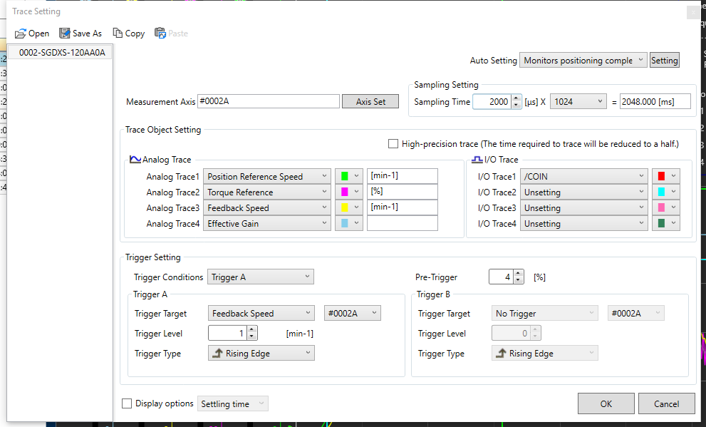

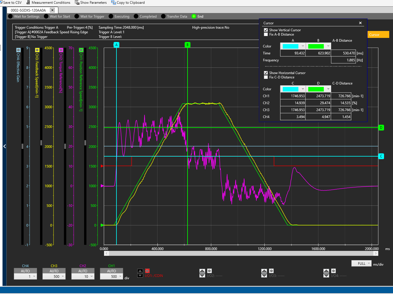
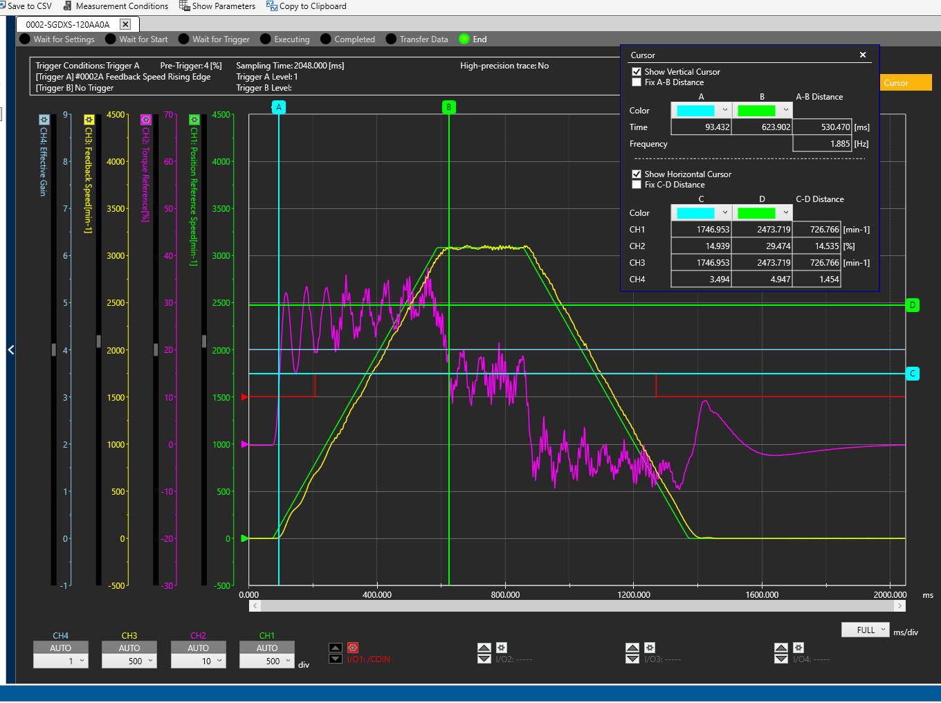
Trace with Speed(yellow) and Torque(purple)
Measure horizontally along the approximate centerline of torque during acceleration.
Enter into Tp (Torque Peak) % of torque during acceleration (Ch:2 - D)
Measure horizontally along the approximate centerline of torque showing the friction during the move at speed.
Enter into Tf (Torque Friction) % of torque at end of acceleration during move (Ch:2 - C)
Enter into ΔV RPM, the RPM during the move at speed. I don't have a horizontal line here on the trace above, I just approximated the motor stabilized at 3100 RPM during the move looking at the scaling on the left.
Measure speed vertically from start of movement to end of acceleration
Enter into ΔT time (ms) spent in acceleration (A-B Distance)
Enter in the calculated Pn103 for each motor and program those in the drives.
System Tuning for Gantry
Manually calculate the inertia (Pn103)
Do a system tune. Ramp up till it gets noisy.
Example values: FF 170, FB 48.
Pull back the tune till it sounds good.
Try to minimize following error.
Graph following error.
Check the following error both axes.
Increase the FF gain by 10s on the non gantry axis to make the following errors match.
Custom Tuning
Enable Tuning Mode
Run Auto Inertia test (Pn103)
Custom Tuning
Make following errors match
Advanced Tuning
If additional tuning is required, you can run through the same procedure above but modify selections on Mode Selection and Mechanical Selection.
You may have to play with Pn100-Pn102. But MachMotion strongly recommends keeping the parameters matching in both drives.
Pn100 (Speed Loop Gain)
Increase to help make the machine more smooth.
Pn101 (Speed loop integral time constant
Increase to reduce rigidity and noise.
Pn102 (Position Loop Gain)
Increase till following error stops decreasing.
You can also go through Chapter 8 (Tuning) of the attached manual ("Sigma-7 Manual Analog-Pulse.pdf").
If auto tuning does not work, you may have to try manual tuning.
Manual/Automatic Gain Switching (Sigma X)
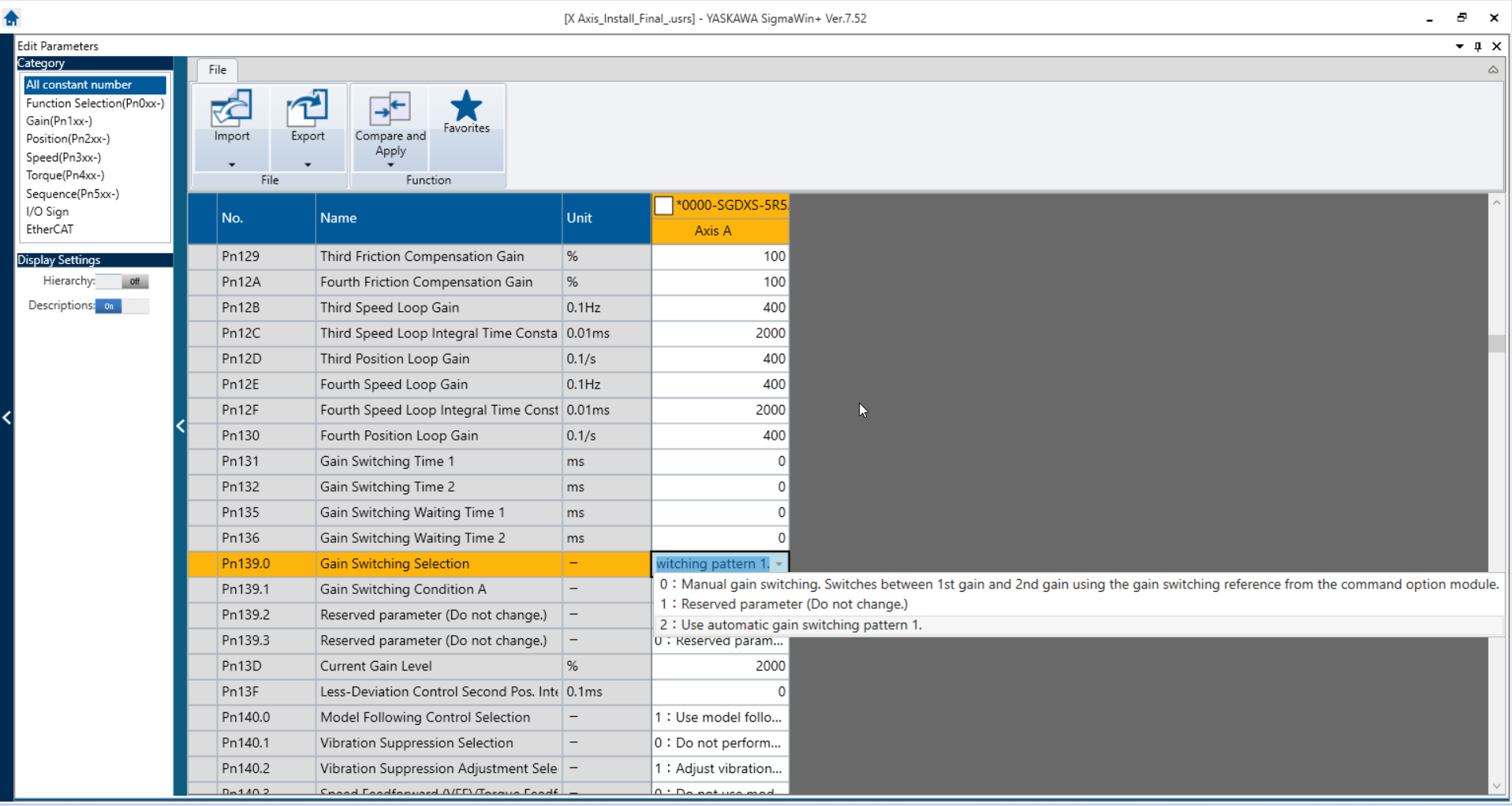

Manual
Use GainTuning SwitchingMode 2 or 3 for CNC applications (Mode 3 is better, less overshoot, turns on Modal Following Control)
Pn139.0When dictatesusing mode 2 or 3 leave Friction compensation enabled
Use whichever Mechanism Selection matches your machine
feed forward level (FF) is the same as Pn141 (which uses an assumed decimal 500 = 50)
Next write some G-code that will bring the all the axis up to full speed for the same distance and then stop, wait a couple seconds and then repeat, going the other way. An M99 at the end will allow the program to keep looping until you stop it. Make sure you use G90 for the safest results!
Make sure all axis are traveling the same distance!! otherwise Mach will interpolate the move and slow the axis traveling the shorter distance and your tune will be inaccurate!!!
Example G-Code using block deletes to select which typeaxis of,will move or be ignored.
___________________________________________________________________________________________________________________________________________
M1
/1 G01 G90 X20 F500
/2 G01 G90 Y5 F500
/3 G01 G90 Z2 F500
G04 P3.
/1 G01 G90 X35 F500
/2 G01 G90 Y-10 F500
/3 G01 G90 Z-13 F500
G04 P3.
M99
___________________________________________________________________________________________________________________________________________
Ensure every axis is in fact reaching the commanded feedrate before matching the position error!!
Push cycle start in Mach and let the machine start cycling
click "start tuning" on each axis and the DROs should turn green

Make your adjustments during the g-code pause, if any,you Gainadjust Switchingwhile ismoving, active.sometimes the drive will throw an error
Option
Use this calculator to determine the proper position error target for each axis.
https://docs.google.com/spreadsheets/d/19xXUOK75FnIN3B1aj_EDSktX5nj8XN5OVXC3Y_g2d-E/edit#gid=0

1:
Input the max position error In inches! you observed earlier during a sustained move, (not during the accel or decel sections of motion)
2:
Input "0:Counts ManualPer GainUnit" Switching"from allows"Configure/Control/Motors" (you must do "Machine Calibration" for this axis first)
Watch "Position Error" in Diagnostics>RapidPath>Motors and start adjusting "Feed Forward Level" until Position Error reaches the target produced by for that axis
Next bring up "Feedback Level" until the axis get's noisy and then back off till it quiets again (usually 10 units or so)

Next bring up feedback load until the axis get's noisy and then back off till it quiets again (usually 10 units or so)
Press feed hold to stop motion.
Click Finish on each axis

Cycle drive power or software reset to finalize the new parameters
CV Feedrate and theory
The theory's applied in the creation of this manual are simply trying to match the lag of each axis in inches! so that in theory one could cut a circle at high speeds and while it might be smaller than programed it would still be a circle and not an egg. The job of the drives to provide smooth motion at the required speeds with equal lag in inches.
We are therefore depending on Mach to sendprovide anthe EtherCAT signalprecision to the drive that can swap between the 4 Gain parameter sets:
Gain Set 1: Pn100, Pn101, Pn102
Gain Set 2: Pn104, Pn105, Pn106
Gain Set 3: Pn12B, Pn12C, Pn12D
Gain Set 4: Pn12E, Pn12F, Pn130
This allows Machsaid to swap to different Gain values on the fly to get different response and performance behaviors for different operations. (EX. Rigid Tapping, Laser Etching, Smooth Shape-Cutting, etc.). Mach will be able to do this with M-Codes (TBD by Andy).
Automatic Gain Switching
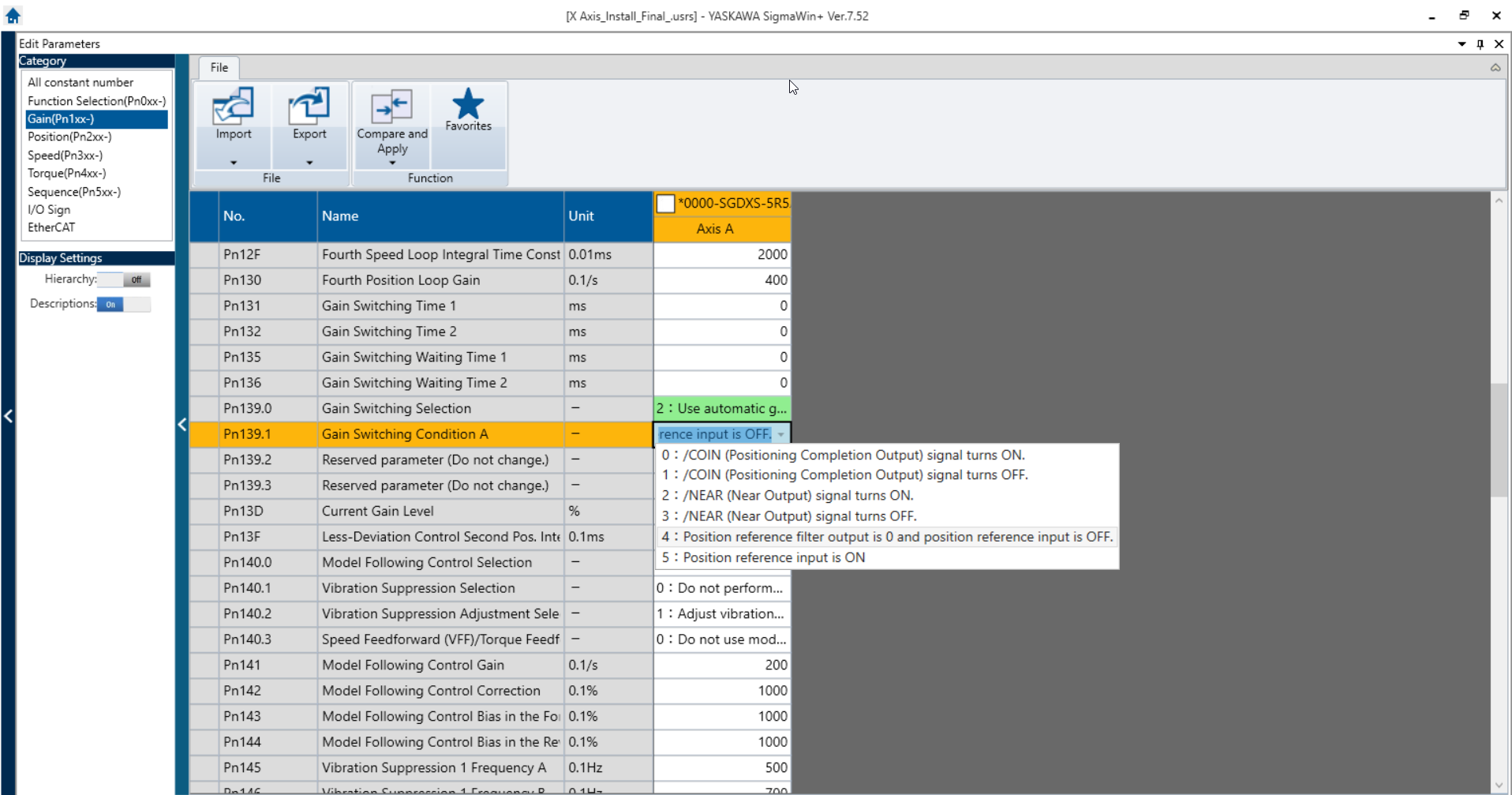
Option "2: Use automatic Gain Switching pattern 1" will automatically cycle the active Gain Set between 1 and 2 when the condition set in Pn139.1 is true.
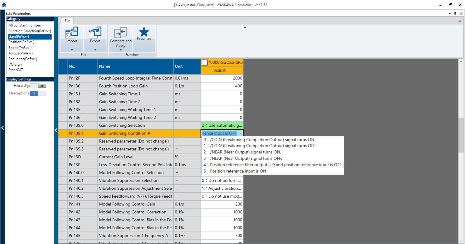
Pn139.1 dictates the condition that needs to be true in order for Automatic Gain Switching to take effect. We currently plan to use "4: Position Reference output is 0 and position reference input is off". This will allow us to swap to a softer set of gains when the motors are not in motion and eliminate the harmonic hum.
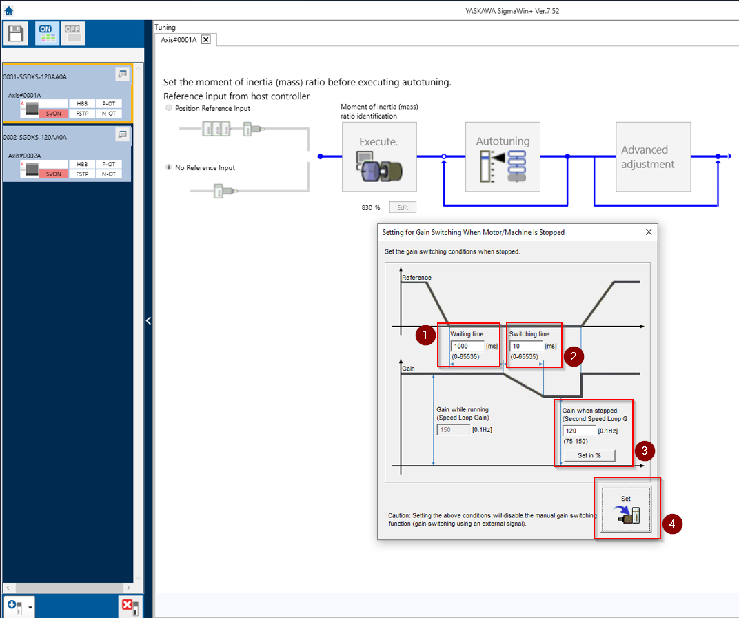
There are settings for the specific conditions of Automatic Gain Switching that can be accessed through Tuning>Advanced Adjustment>Gain Switching. This will bring you to the dialog below. There are 4 fields to input data into:
"Waiting Time" dictates how long the condition of Pn139.1 must be true before the gain switching activates.
"Switching Time" dictates how gradually the changes in between Gain Sets 1 and 2 ramp down. (This may need adjust if the process of switching gains causes a clunk or a hum)
"Gain When Stopped" dictates a percentage of Gain Set 1 that will be applied to Gain set 2 when the switch happens. (Usually this is will be obsolete because Gain Set 2 will be manually changed to desirable values).
"Set" will modify the Pn139.0 to value "2: Use Automatic Gain Switching" and adjust the value of Pn106circle to be the percentageproper size, that youis selectednot the drives job.
Mach has two tools for this, acceleration and CV feedrate. on a fast rigid machine (like a good router) acceleration should be pretty high, probably over 60 and ideally match across all coordinated axes, though this doesn't appear to be completely necessary.
CV feedrate is needed to obtain part precision by overriding the commanded feedrate during angle changes since most post processors don't slow feedrates for angle changes.
It is turned on and scaled the MachMotion plugin and can be viewed in fieldthe 3.
tab
advanced CV (G64.2) is necessary once you start cutting above about a couple hundred IPM since corners start rounding.
Without advanced CV motion is smooth, just not accurate at high speeds. We also see a pronounced entry mark from the Z, the tool appears to be finishing the ramping leadin while cutting
G5.1 R0 is full CV mode, activates G64 (full gas, does not slow for angle changes, use on files trying to program arcs with only G01 moves)
G5.1 R1 slows some for corners, activates G64.2 (Uses the full "path error tolerance" amount in the MM plugin, is full gas within G64.2)
G5.1 R10 slows completely for corners, activates G64.2 (Slows down much more than than an R1 will, is full brakes within G64.2, this is a nice middle ground between R1 and G61)
G5.1 R5 is halfway between R1 and R10
sometimes it's nice to use a pound variable and let the operator adjust it as needed on the dashboard. G5.1 R#501

9103