
CTB Servo Drives

1. Introduction
MachMotion offers two series the GH single axis and MAS multi axis drives. The GH can be used as a single axis servo drive and can be connected to a range of PM motors or can be used to drive a AC induction spindle motor. The MAS come in to versions 3 and 4 axis.
The drives all use EtherCAT for communication from the drive and controller.
Configuring a CTB Spindle:
The CTB drives can be configured to use the encoder on that is built into the motor or a external load encoder for position feedback. The encoder on the motor should always be connected to the drive with connector T5. Every spindle drive is expected to have the correct braking resistor installed.
External Load Encoder
The external encoder must be a 5V TTL quadrature encoder with A,B and marker pulse to be used for orientation of the spindle. It is very important that the external encoder is mounted 1:1 ratio to the spindle load.
- Encoder wiring:
Function Cannon Plug DB15 Pin Number 0V K 4 5V H 3 A A 2 /A N 1 B C 7 /B R 6 Z B 12 /Z P 11 Shield Shell - Encoder parameters:
Parameter Name Descriptions Factory Setting C1-03 Position Feedback Source 0: Motor Encoder (T5)
1: External Encoder (T4)
0 C1-04 Position Operation Source 0: Invalid
1: Motor Encoder (T5)
2: External Encoder (T4)
1 E1-15 External Encoder Type (T4) 0: Invalid
1: Quadrature
1 E1-16 External Encoder Pules Count (T4) 0~16348 1024 E1-17 External Encoder Direction (T4) 0: Clockwise
1: Counterclockwise
0
Brake Resistor
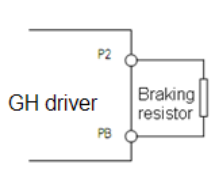
- Connection of braking resistor
The P, PB terminals on main circuit block of AC servo driver are for connection with braking resistor.
Please do not connect braking resistor to other terminals, otherwise, the braking resistor will heat up and
burn out, or cause damage to the driver.
Specification of braking resistor
BKSC-XXXX GHX 43
P745
P547
P540
1140
1540
1840
2240
3040
3740
4540
5540
7540
9041
1041
3241
6042
0042
50
43
15
Power
W60
080
010
0060
080
010
0010
0015
0020
0020
0025
0025
0025
0025
0020
0020
0025
0025
00
25
00
Resist
ance
Ω50 40 32 50 40 32 32 32 20 20 20 20 20 20 20 20 20 20 20 Qty. 1 1 1 2 2 2 2 2 2 2 2 3 3 3 4 4 6 6 8
- Parameters setting
Set the following parametersParameter Name Descriptions Factory Setting P1-01 Buss Over Voltage Alarm 0~10000
800