M31 Motion Control Setup Manual
![]()
The M31 is a compact, industrial motion controller designed specifically for MachPro CNC systems. It links your MachPro control PC to your drives and motors over Ethernet and supports both EtherCAT and traditional step-and-direction control, giving you flexibility in how you build or retrofit your machine. With support for up to 12 axes, the M31 scales from small routers and mills to large, multi-axis specialty machines, while maintaining synchronized, precise motion across all channels. It’s engineered as the motion “engine” of the MachPro platform, providing a stable, factory-certified hardware layer between your Windows control PC and the field hardware on the machine.
WARNING!
Improper installation of this motion controller can cause DEATH, INJURY or serious PROPERTY DAMAGE. Do not attempt to install this controller until thoroughly reading and understanding this manual.
1 Introduction
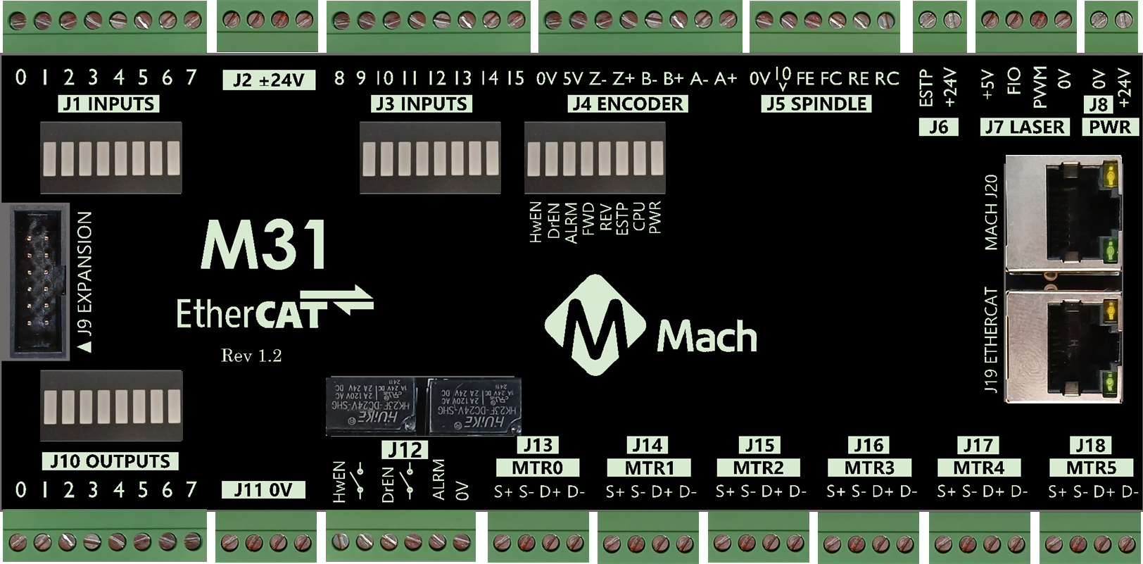
Reference Diagram
Use the diagram below as a reference throughout the manual.
Specifications
Below are the specifications for the M31 motion controller.
Please observe the max voltage on each pin. Some pins are 24v compatible, some are 5v, some are 3.3v, and some are 0v. Exceeding their max voltage will cause serious damage to the M31 Motion controller.
|
Item |
Specification |
|
Input Power |
24VDC |
|
Max Power Consumption |
48W |
|
|
|
|
Motors |
|
|
Stepper Channels |
6 motors |
|
Step and Direction Axis Control |
5V Single Ended and Differential |
|
Connection |
Terminal Blocks |
|
Max Pulse Speed |
1.6 MHz |
|
|
|
|
Ethercat Network |
|
|
Device Types |
Servo Motors, Stepper Motors, VFDs, I/O Modules, etc |
|
Max Devices |
30 |
|
Max Motors |
6 motors by default (8 and 12 motor options available) |
|
|
|
|
Quadrature Encoder Channel |
1 |
|
Connection |
Terminal Blocks, 5V Differential |
|
Max Frequency |
1.6 MHz |
|
|
|
|
Spindle |
1 |
|
Opto-Isolator Outputs |
Forward and Reverse Open Drain / Open Collector outputs |
|
Analog Speed Signal |
0-10VDC |
|
Encoder Feedback |
Yes |
|
|
|
|
Digital Outputs |
8 (PNP Sourcing) |
|
Voltage |
16 - 24VDC |
|
Max Current |
250mA |
|
Pulse Wave Modulation (PWM) |
Not yet available |
|
|
|
|
Inputs |
16 (PNP Sourcing) |
|
Voltage |
16-24VDC |
|
Input Current Range |
3 - 6mA |
|
Isolated |
Yes |
|
|
|
|
Enable Circuit |
2 |
|
Hardware Enable |
Relay Dry Contacts, 5V Enable or 24V Enable |
|
Drive Enable |
Relay Dry Contacts |
|
|
|
|
Emergency Stop Circuit |
Normally Closed Connection |
|
|
|
|
Ethernet Port |
10/100 MHz |
|
|
|
|
Dimensions |
7.125"(L) X 3.75"(W) X 1.875"(H) |
|
Optimal Temperature Range |
32° to 100°F (0° to 38°C) |
|
Humidity |
30% - 60% RH |
Status LEDs
Each LED has a single color.
| LED | ON | OFF |
| Power | Green - M31 is powered | No Power |
| CPU |
Blue blinking - M31 CPU is active
|
CPU is not enabled |
| E-Etop | Red - E-Stop pressed, or the E-Stop circuit is incomplete | E-Stop is not active |
| Hardware enable | Orange - hardware enable is on | No hardware enable signal |
| Drive enable | Orange - drive enable is on | No drive enable signal |
| Spindle fwd | Green when spinning forward | |
| Spindle rev | Green when spinning in reverse | |
| Drive alarm | Red - one or more drives are in alarm state | All drives report good |
Tools Required
A small, flat head screwdriver is needed for the I/O terminals.
Recommendations
If your system is running 480 VAC we recommend using line filters before the servo drives and VFDs. At higher voltages they generate a lot of electrical noise which can affect the logic circuits in your system.
The M31 Motion Controller and the drives can supply 24VDC, but they do not have a lot of output capacity. We recommend adding separate 24 VDC power supplies. Specific suggestions for success:
-
Use separate 24 V supplies for I/O and field loads if current is high.
-
Tie all 0 V terminals to a single 0 V / ground bar in the main cabinet.
-
Bond this bar to PE at one place.
-
Keep motion controller and drive I/O referenced to this same 0 V bar.
-
Use isolated I/O for external panels and long cables.
This approach prevents large ground potential differences while still offloading the 24 V outputs on drives and motion controllers.
Firmware Update
On your first start of the MachPro software, it will check to ensure that you have the latest firmware for the M31 motion controller. If not, you will see an update screen.

Follow the prompts to update the M31 firmware. When it has completed the process, it needs to reboot the M31, and it will prompt for your approval to do that. Once the M31 is running again, and both the Firmware and FPGA are current, close the M31 Upgrade window.

Restart the MachPro software to ensure smooth operation.
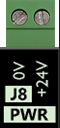
Hardware Startup
To power the M31, you must supply 24VDC to the power connection located at the top right of the board as shown below. The LED labeled PWR will be green when 24VDC is supplied.
Emergency Stop (E-stop Circuit)
The emergency stop connector is located in the upper right corner of the M31. When the emergency stop terminals are connected together, the red E-Stop LED turns on and the controller can then enable. This is a safety circuit that immediately stops motion when activated.
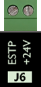
Important: The M31 motion controller will not operate unless the Emergency Stop (E-Stop) circuit is complete.
Multiple E-Stop Devices
-
Connect all E-Stop devices in series in the same E-Stop circuit.
-
In a series circuit, any open contact will open the entire E-Stop circuit.
Adding an E-Stop Button to the M31 Board
-
Wire the E-Stop button to a relay input.
-
Use the relay output contacts in the E-Stop circuit.
-
Ask a qualified electrician to design and verify this wiring.
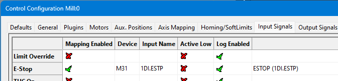
M31 Emergency Stop Input Mapping
-
The Emergency Stop input is mapped to M31 1DI.ESTP.
-
When configured correctly, opening the E-Stop terminals will disable the system.
-
The system will only operate when the E-Stop circuit is closed and healthy.
Hardware and drive enable overview
Before you use hardware enable or drive enable, configure the emergency stop circuit.
The M31 includes two control circuits: hardware enable and drive enable.
These circuits remain inactive until you configure the emergency stop (E-stop) circuit.
Use the default settings unless your application requires changes.
Accessing the enable settings
-
Open Configure > Control.
-
Select the Settings tab.
Available options
In the Settings tab, you can:
-
Set the delay between hardware enable and drive enable.
-
Choose which outputs turn off when the system disables.

Configure the Dedicated Network Interface
The M31 motion controller connects to the control computer through a static IP Ethernet connection.
Follow the Microsoft guide below to manually set your network adapter to communicate with the M31:
Microsoft Instructions: Manually Configure IPv4 Settings Scroll to the bottom and expand the section titled “To specify IPv4 settings manually.”
Then perform the following steps:
-
Set IP address to:
192.168.208.10 -
Set Subnet mask to:
255.255.255.0 -
Save the settings and close the window.
-
Connect the Mach J20 port to the dedicated network port on the control computer.
The M31 IP address (192.168.208.35) and the computer adapter IP (192.168.208.10) are pre-configured and should never be changed.
Verify MachPro Compatibility with the M31 Controller
For the M31 to function correctly with MachPro, the M31 must have the latest firmware and FPGA version.
Verify Installed Versions
To check, follow these steps below:
-
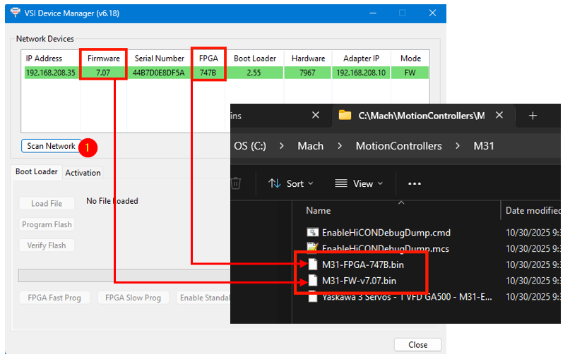
Open VSI Device Manager located at:
"C:\Program Files (x86)\Vital System Inc\VSI Device Manager\" -
Click Scan Network.
-
Compare the Firmware and FPGA versions shown with the files in
C:\Mach\MotionControllers\M31.
If they match, the system is ready. You may close all windows and continue.
Note: If you cannot find the M31 when you scan network, the M31 IP address may not yet be configured to the current default IP. On the bottom right side of the VSI Device Manager, type in 192.168.208.35 and press Set New IP Addr. Cycle power on the M31 and you should be able to see it in the VSI Device Manager. 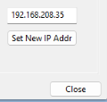
If they do not match, follow the next steps to update the M31.
Update Firmware and FPGA on the M31
-
After scanning the network, locate your M31 in the device list.
Click it once — the row will turn blue. -
Click Switch to Loader.
The row will change to tan, indicating Loader mode.
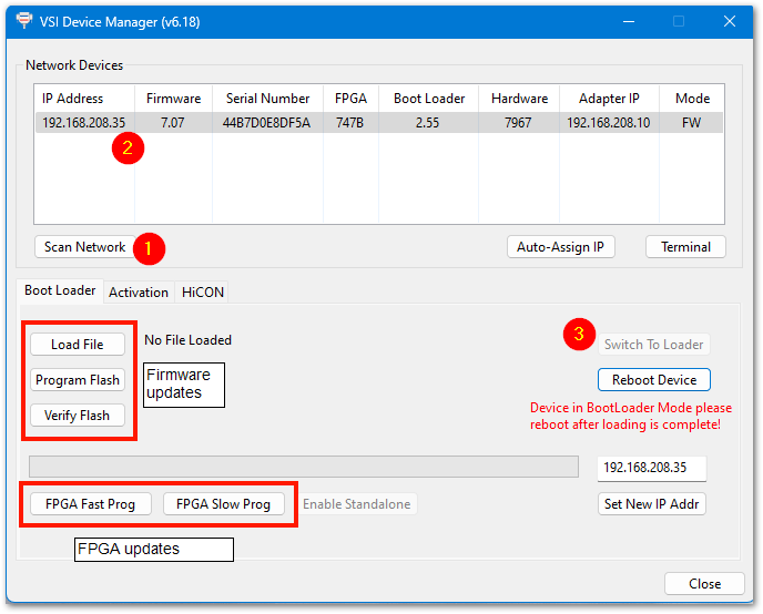
Updating the FPGA:
-
Click FPGA Fast Prog.
-
When prompted, navigate to
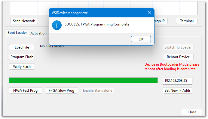
C:\Mach\MotionControllers\M31and select the FPGA file. - Follow the prompts to complete the update.
-
Click Reboot Device and wait for the confirmation that the operation is complete.
Updating the Firmware:
-
Click Switch to Loader again.
-
Click Load File, and select the firmware (
.FW) file fromC:\Mach\MotionControllers\M31. -
Click Program Flash to install it.
- Click Reboot Device and wait for the confirmation that the operation is complete.

When both updates finish, click Scan Network again and verify that the Firmware and FPGA versions now match the MachPro package files.
MachPro Startup
On the desktop of your control, there is a MachPro shortcut for your machine type. Below is an example of the MachPro shortcut.
![]()
After double clicking on your MachPro shortcut, a window will come up asking to Press Cycle Start to Enable Mach and Home All Axes . By default on a new installation, MachPro will just home in place. Press [Cycle Start] and the control will enable and home all axes.

This prompt can be turned off in the MachPro settings if desired.
The configuration menus are locked if the system is enabled, and all the menu options will be grayed out. You need to disable the system in order to make configuration changes.
2 Axis Setup
M31 Motion Controller
All of the drives and external I/O will be wired into the M31. The M31 motion controller uses either EtherCat or step and direction to control the axes.
The axis drives and motors need to be wired, configured, and calibrated for accurate motion in section 2. Once that is completed, machine zero, limits, homing, and fixtures can be configured in section 3.
Step and Direction Connection and Configuration
The M31 supports differential or single-ended outputs. For differential outputs there are two signals for step (step + and step -) and two signals for direction (direction + and direction -). For single-ended there is only one signal for both step and direction.
|
Motors |
|
|
Stepper Channels |
6 Motors |
|
Step and Direction Axis Control |
5V Single Ended and Differential |
|
Connection |
Terminal Blocks |
|
Max Pulse Speed |
1.6 MHz |
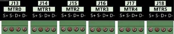
If using step and direction, wire up your drives to J13-J18.
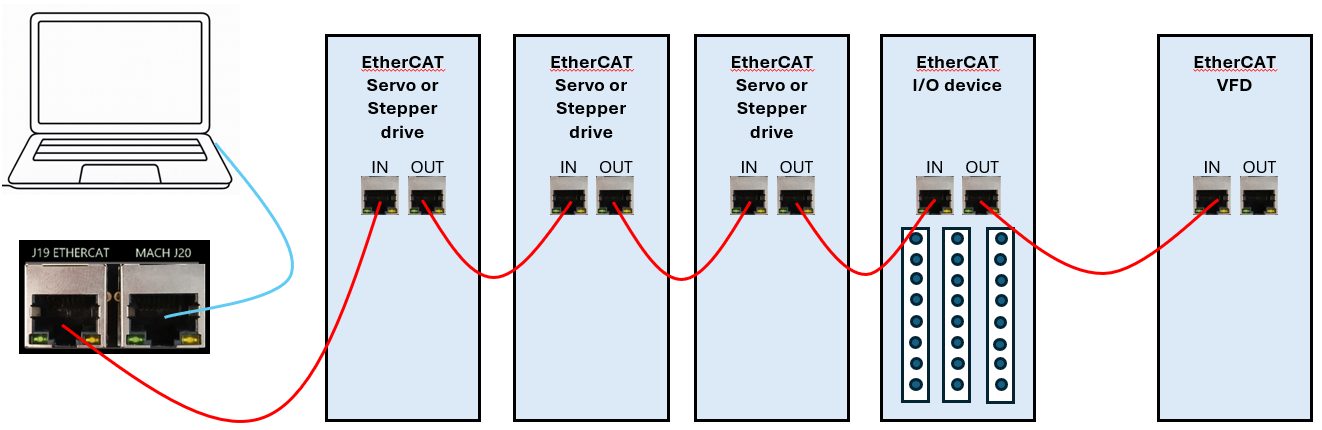
EtherCat Connection and Configuration
The M31 uses a standard EtherCat physical connection plan. The computer connects via Ethernet to J20 on the M31 motion controller. J19 on the M31 is then used to connect to each of the EtherCat devices.
-
Put servo & stepper drives first in the EtherCAT chain (closest to the controller).
-
Put I/O devices and safety relays in the middle.
-
Put VFDs last (at the end of the chain). VFDs make electrical noise — keeping them last lowers interference.
-
Use shielded network cable for all EtherCAT devices.
-
Cable length: keep each cable between 1 foot and 100 meters (about 0.3 m – 100 m).
-
Good cable management: keep cables neat, do not bend them sharply, and separate network cables from high-power lines when possible.
Load the EtherCat configurations
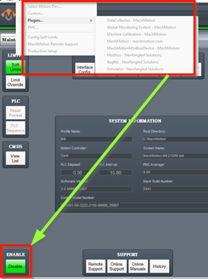
Pull down Configure -> Plugins -> M31 and select the EtherCAT tab


After downloading the configuration you will need to close the open window and restart MachPro for all configurations to be loaded.
If the list of online devices in right column does not populate with valid devices, please contact MachLabs support.
Configure individual EtherCAT motors
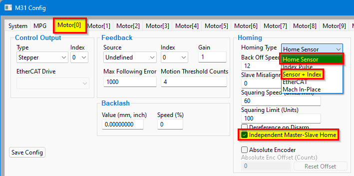
After restarting MachPro pull down Configure -> Plugins -> M31 and select the Motor[0] tab
The example below shows Motor[0] configured as an EtherCAT drive and connected to a Leadshine drive [1]L7N(COE)
- Select EtherCAT Drive as the Control Output Type
- Select the first EtherCAT Drive for Motor[0]
- Select ECAT Feedback as the Feedback Source
- Select the type of Homing configuration you are using for this motor.

Notes:
- Each motor has a Control Output SubID, and Feedback Index. The default is to leave those fields set to 0 for all motors.

- The maximum following error is usually set to one or two rotations of the motor shaft. You may need to adjust for your system. Following error occurs when an axis is physically blocked from moving, or when part of the axis mechanics are slipping and commanded motion does not result in feedback motion.
- Under the homing section are the adjustments for gantry squaring, and for enabling Absolute Encoder.
- All unused motor tabs need to be set to Undefined


Enabling Axes
After the drives are connected to the M31, open up MachPro, and enable the axes as follows:
Note: This may already be setup depending on your system.
- Enable all the motors that are to be controlled by setting the respective boxes in the right pane to checks. In the example below, motors 0, 1, and 2 are enabled.
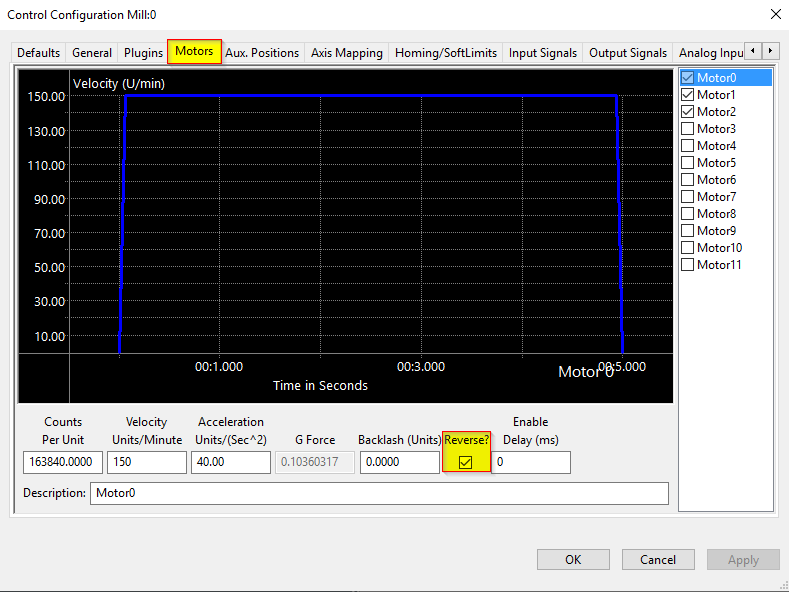
- If a motor moves the wrong direction, it can be reversed in the MachPro. Check the Reverse? box if the motor direction needs to be reversed. The motor will now move the opposite direction than it did before. If the homing direction was already set, it will need to be reversed as well. (see the homing section ). NOTE: If you are needing to reverse direction on an axis with a slave motor, you may need to change the direction for both the master and slave axis.
- Press [ Apply ] to save any changes.

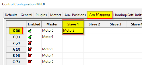
- Next, select the Axis Mapping tab as pictured below. Associate the enabled motors to the applicable axis. In this example, Motor0 is the X master, Motor1 is the Y master, and Motor2 is not mapped to an axis. In this EtherCat system the VFD and spindle are motor 2, but will not be used for axis movement. No slave axes are configured on this system.
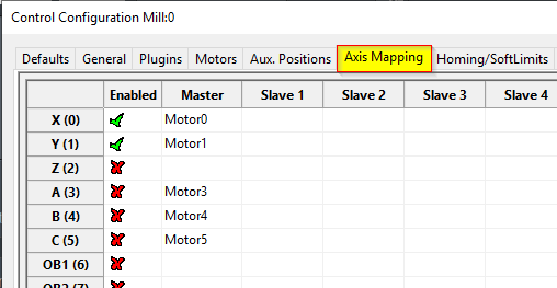
- If you have an axis with two motors - such as a gantry - one motor will be the master and the second will be the slave. In the slave column, select the motor that will be running in slave mode. In this example X axis has Motor0 as the master and Motor2 as the slave.

- Press [ Apply ] and [ OK ] to save and close.
- Carefully test jogging. If you have a gantry with two motors, you may need to reverse one motor for correct motion. See step 2 above.

The system should now be able to jog, however,....
WARNING
The machine can be crashed very easily at this point. The axes need to be calibrated and the limits set up now.
EtherCAT Drive Configuration
Before calibrating EtherCAT servos, you must know your motor resolution and cap it to 17 bits or 131072 per motor revolution.
17 Bit Resolution
Motion based on 17 bit encoders is accurate enough for the majority of CNC systems, and it also allows you to select from a range of servo drives and motors. However, the drives will need to be configured to provide 17 bit encoder output even if they support a higher encoder count. This is a configuration change that is often made on servo drives, and it may be listed as Drive Ratio, User Parameter, Encoder Output Resolution, or Edge/Pitch.
Yaskawa Sigma5 and Sigma7 drives use parameter PnB02 set to 8 to change their output to 17 bit.
Each drive manufacturer has its own way to adjust the number of pulses that it will report for each rotation of the motor shaft. You need to ensure that you can configure any drives you plan to use with the M31 for 17 bit output.
| Count | Bits | Conversion | Result |
|
less than 131,072 (stepper drives) |
less than 17 | none | use the maximum resolution of the drive |
| 131,072 | 2^17 | none needed | 131,072 |
| 1,048,576 | 2^20 | 8 | 131,072 |
| 8,388,608 | 2^23 | 64 | 131,072 |
| 16,777,216 | 2^24 | 128 | 131,072 |
Example of how the math works: The last row is a 24 bit drive.
2^24 = 16,777,216 pulses for each rotation of the motor shaft. Try dividing that by these numbers: 8, 16, 32, 64, 128
In this case 16,777,216 / 128 = 131,072 which is the number of pulses we are looking for. So, if you have a 24 bit drive, you need the drive parameter where you can plug in 128, and have the drive send 131,072 pulses per rotation to the M31.
Checking Resolution
How many bits is your drive sending to the M31? This process is easiest if the motor is not mounted on the machine.
- Power up the system and MachPro, but leave MachPro disabled
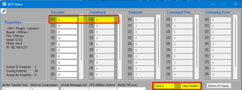
- Pull down Diagnostic | M31
- Determine which axis you are checking and clear its position data. In the example above, Axis 0 has been selected. When the Clear Position button is pressed, the feedback value will be zeroed.
- Now rotate the motor shaft one full rotation and note the feedback value. If it is a stepper motor, you may see approximately 10,000. If it is a servo motor you should see a number close to one of the numbers in the first column of the table above.
- If it is more than 131,072, your goal is to reconfigure the drive so that 1 rotation of the motor shaft produces approximately 131,072 pulses.
Axis Calibration
Before calibrating the axes, set the backlash units to 0 for each axis. See the Backlash Repair and Compensation section below for details.
Go to Configure-> Plugins -> Machine Calibration.
Select the type of configuration you would like to perform from the window:
- Manual - Calculate the axes by comparing distance traveled vs. distance commanded. See Manual Calibration below for instructions.
- Automatic - Calibrate axes using the specifications of your system. Continue for instructions.
Automatic Units Calibration
Automatic calibration requires you to provide all of the details of your motor and axis hardware. If you are unable to find this information, proceed to the Manual Calibration section.
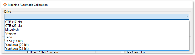
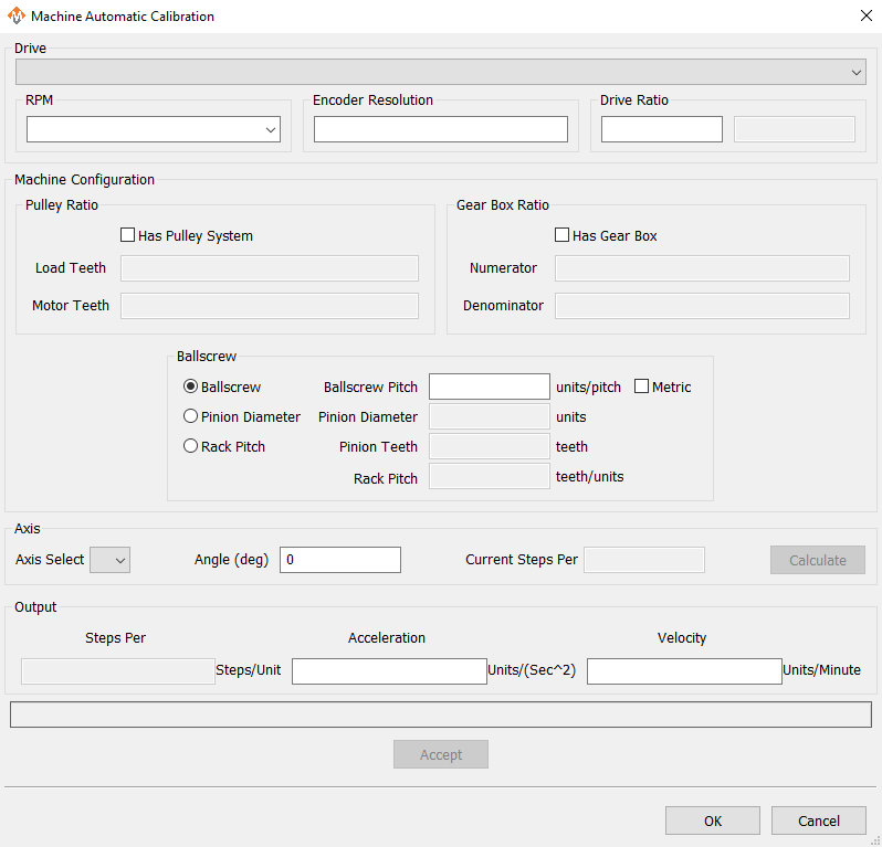
- Select the Drive that most closely matches yours. If there is not an exact match, select based on the number of encoder resolution bits.
- Select the max motor RPM
- Enter 131,072 for the Encoder Resolution. If you have a stepper drive, or the drive is less than 17 bit, then enter the actual resolution per rotation for your motor. To verify the actual encoder resolution of your drive, please use the steps above in Checking Resolution.
- Enter 1 for the drive ratio.
- If this axis uses a pulley, select that box and enter the number of teeth from the load side and the motor side.
- If there is a gearbox, select that box and enter the ratio.
- This axis will have either a ballscrew or rack and pinion system. Select the type it has and complete the open fields.
- Select the axis to calibrate.
- Leave Angle at 0 degrees
- Press the [Calculate] button.
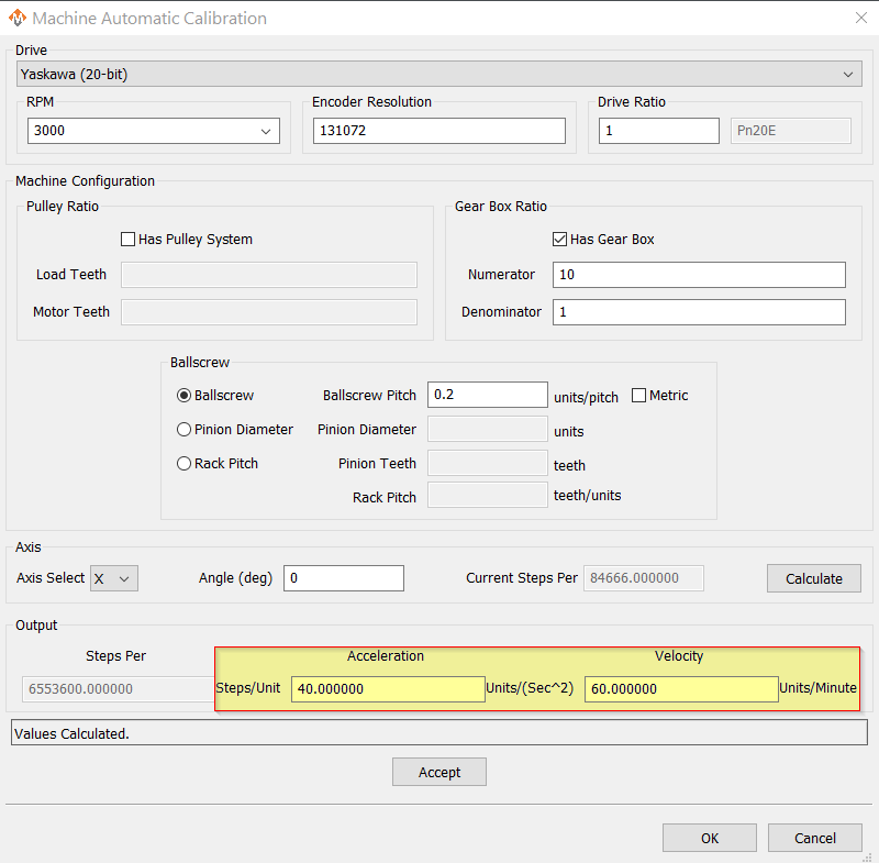
- Evaluate the current steps value against the proposed values. You may change values and re-calculate.
- When you are ready to Accept the new steps per value, enter in the maximum Acceleration and Velocity values that you want for this axis.
Repeat for each axis.
Press [OK] and restart MachPro to save the calibration settings.
This is an example of a simple X axis that has been calculated and is ready to be accepted. You may need to change the Acceleration and Velocity values to be appropriate for your machine.
Verify that each axis is moving the distance that you command.
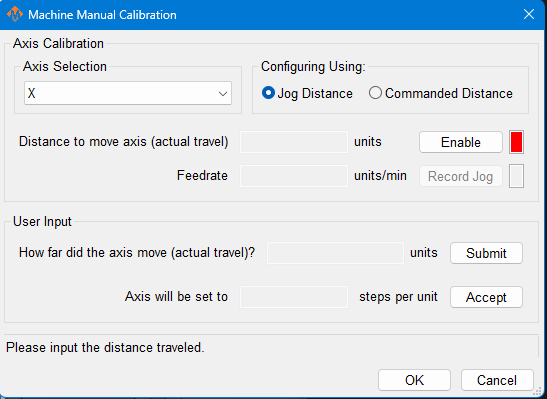
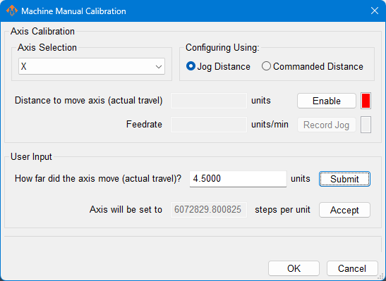
Manual Calibration
This tool will enable you to calibrate your axes based on measuring actual distances moved and updating the MachPro parameters. Use the longest distance that you can accurately measure to calibrate each axis.
You will be commanding motion on each axis. Carefully jog each axis to the middle of travel before starting calibration.
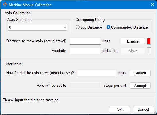
- Select the axis to calibrate.
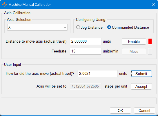
- Select either Jog Distance or Commanded Distance. Jogging allows you to directly control the speed and distance the axis moves.
|
Manual Calibration Using Jogged Distance |
Manual Calibration Using Commanded Distance |
|---|---|
|
|
|
|
|
|
Pressing [ Accept ] at this point will update the steps per unit on this axis
|
Pressing [ Accept ] at this point will update the steps per unit on this axis |
Axis calibration is a core function of a CNC control. Ensure that it now meets your accuracy requirements before moving on in the configuration. All of the following configuration steps depend on calibration, and if you later change the calibration, you will need to reconfigure many of the items below.
Configure Velocity and Acceleration
If you want to adjust your velocity, select Configure on the top menu bar, then Control . Select the Motors tab as shown below.
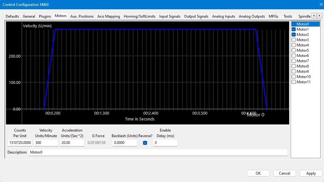 In the right pane, click on the motor you want to set up.
Click the word to highlight and select the axis. The checkbox is for enabling/disabling the motor
The selected motor’s parameters will be loaded and the velocity or acceleration settings can be adjusted.
- The max velocity is limited by several factors, including the motor. If you want an axis rapid speed to be limited or lowered, adjust the velocity for that motor to the max speed you want the rapid to be. The rigidity of the machine hardware will limit practical maximum velocity of an axis. The cut quality and accuracy will degrade as it reaches that point.
- For stepper motors, max acceleration is typically 15-20 if in standard units. For servo motors, start with value of 30-40. This parameter also sets the deceleration rate, which interacts with a regeneration resistor - if one is installed on this axis.
Press [ Apply ] before clicking on another motor or closing out the Mach Configuration window. NOTE: If you change the counts per unit, the velocity and acceleration values will adjust accordingly. If you do not want them to change, type in the current values shown. Verify by clicking another motor and then coming back to the adjusted motor.
WARNING
No limits have been set up. DEATH, INJURY or serious PROPERTY DAMAGE can occur if the system is not operated carefully. Limits and homing setup will be completed in section 3
Backlash Repair and Compensation
Backlash is caused by the gaps between moving parts such as gears and ballscrews. It is the amount of movement one component can make in one direction without causing motion in the next connected part. Most mechanical systems have some backlash - even when new. If the mechanics are too tight, binding and excessive wear will result. As the gears and ballscrews wear, the backlash will increase, and accuracy will decrease. Ongoing testing and maintenance of your mechanical system is required to minimize backlash.
The M31 provides software backlash compensation as a short-term solution for small, stable amounts of backlash. To calculate the backlash of an axis use How To Test For Backlash
Backlash Value – (Enter in Configure | Plugins -> M31). This field sets the backlash amount in inches or millimeters, depending on the setup units. For best performance, backlash should be less than .0015 inches. Start by entering half of the backlash value, test and adjust.
Backlash Speed % – (Enter in Configure | Plugins -> M31) This is a factor of the axis acceleration value. The M31 takes the max acceleration of the motor and multiplies it by this percentage. Valid values are 10-400 (0.1 to 4 times max acceleration). A common value is 20%.

Do not leave the backlash speed value at zero if you enter a backlash value. The M31 will not function.
All of the axes are now calibrated, but MachPro does not know where the limits of travel are on each axis. That will be configured next. Until that setup is completed, be very careful if you are moving axes.
3 Inputs and Homing Setup
You will first need to wire the inputs and outputs to the M31. Then you will map the appropriate software signals to those hardware connections.
|
Inputs |
16 (PNP Sourcing) |
|
Voltage |
16-24VDC |
|
Input Current Range |
3 - 6mA |
|
Isolated |
Yes |
Wiring Inputs
The M31 motion controller has 16 PNP inputs that can be used for the limit and home switches, probes, and other sensors.
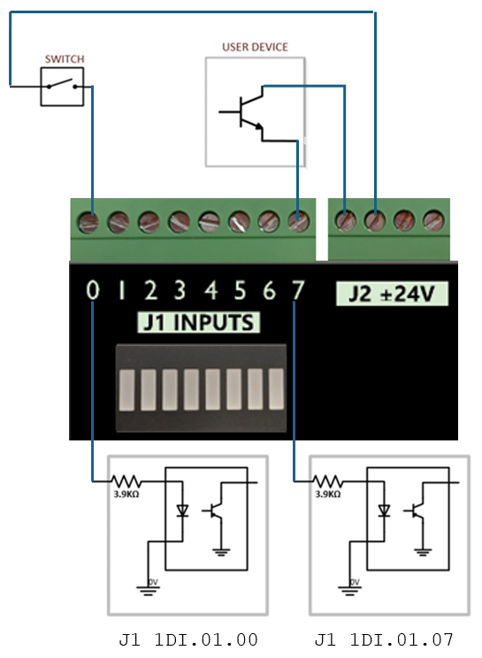
Note: For the highest level of safety, wire the limit switches Normally Closed. If a limit is tripped, or a wire or limit is damaged, the system will stop motion.
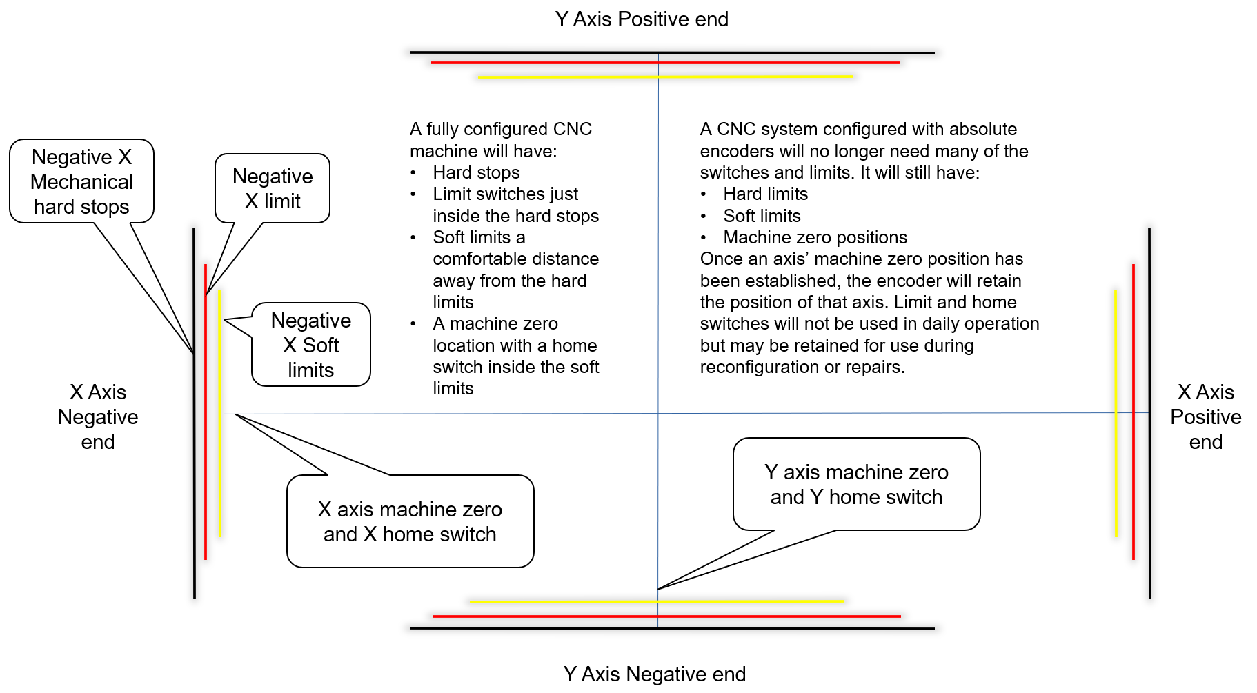
To wire 24V limit switches, follow the steps outlined below.
-
- Select, or install, two limit switches at the end of each axis' hard limits.
- Wire the two switches in series, normally closed. If either limit is tripped, the circuit will open and motion will stop.
- I/O ports are limited, and wiring the limits for a given axis in series conserves those limited ports while maintaining function.
-
Note that safety circuits often require each limit to have its own input.
- Wire one side of the first switch to +24V from the M31 motion controller.
- Wire the other side of the limit switch into an input on the M31. Label the wires and document the I/O.
Wire a home switch on each axis to a separate input.
Tip for success: Once you understand how to wire and map inputs and outputs, complete the charts in the appendix at the end of this document.
Mapping Signals
Short example
-
Motor 0: Home, ++, and -- are enabled (green check).
-
All limits are wired normally closed.
-
We use M31 1DI.01.09 for both ++ and --.
-
We use M31 1DI.01.08 for the Home switch. Using a separate input for Home is more reliable.
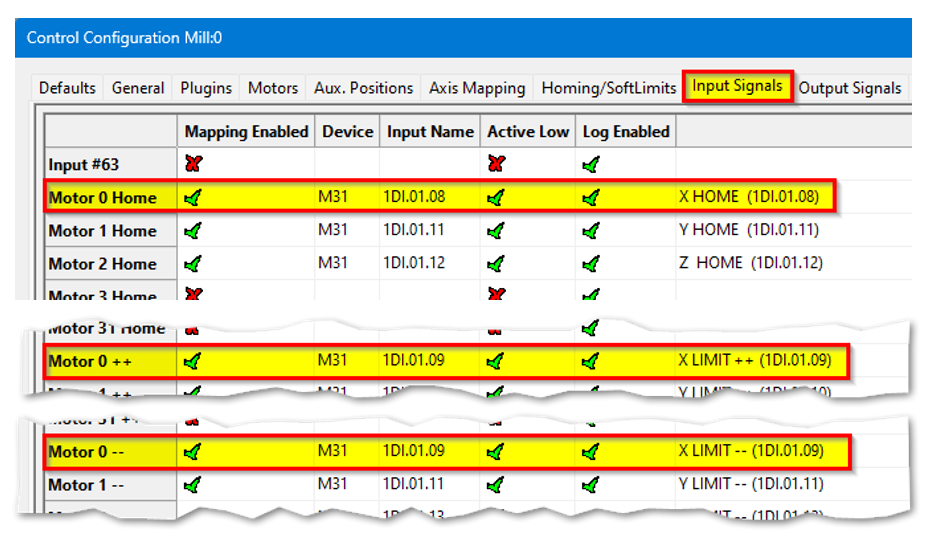
Manually trigger each limit switch and make sure they disable Mach before continuing. This verifies both the wiring and signal mapping.
Homing Setup
-
Danger: If limit switches are wrong or an axis moves the wrong way, the machine can crash.
-
Do this first: Keep your hand on the Emergency Stop button the first time you run homing.
-
Open the settings: From the menu bar click Configure → Control. Then click the Homing/SoftLimits tab.

-
Home Dir: Pick the direction the axis will move to find home — positive or negative.
-
Home Order: Set the order of homing using numbers (1 = first, 2 = second, etc.).
-
Tip: Z is often set to 1 so it moves up first and stays out of the way.
-
-
Home Speed%: Set how fast the axis homes by choosing a percent.
-
20% is the usual maximum for best results.
-
Slower speeds help stop over-travel.
-
You can jog (move) the axis quickly close to the home position before homing to save time.
-
-
Home In Place: Set this based on your hardware in the M31 config:
-
If you use home switches wired through M31 → make sure Home In Place shows a red X.
-
If you use absolute encoders in M31 → make sure Home In Place shows a green ✓.
-
-
Save: Press OK to save your changes.
-
Test: Home each axis one by one to check the settings. Then press Home All to verify everything works.
Homing Slave Axis
There are 2 configuration options:
1. Homing with the home switch only on the Master
|
Open Configure → Control → Axis Mapping.
|
 |
|
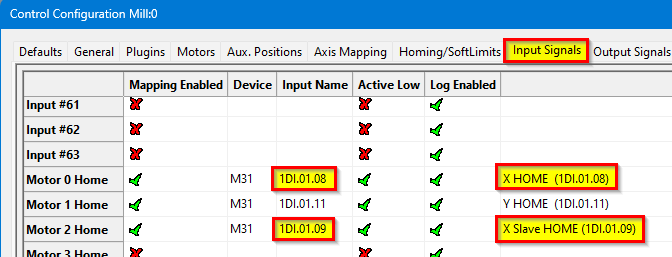
Open Configure → Control → Input Signals.
|
|
|
Open Configure → Plugins → M31. The configuration for the master and slave motors are the same.
|
|
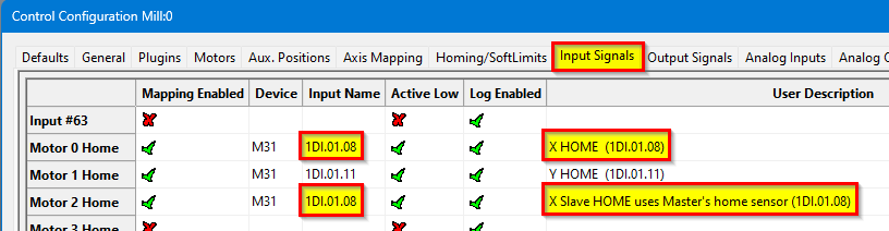
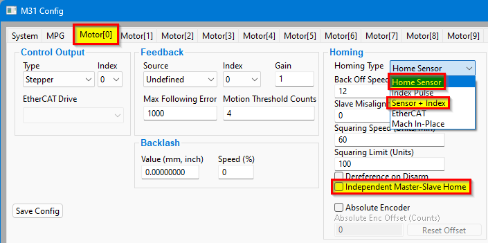
2. Homing with both Master and Slave having their own home sensors
|
Open Configure → Control → Axis Mapping.
|
|
|
Open Configure → Control → Input Signals.
|
|
|
Open Configure → Plugins → M31. The configuration for the master and slave motors are the same.
|
|
Set Slave Misalignment value if needed to "square" the gantry
https://support.machmotion.com/books/knowledge-base/page/aligning-slave-axis-gantry---mach4
Troubleshooting
-
What it means: The home switch used for the master may actually be wired to the slave (they are swapped).
-
What happens: When you touch off switches and home, one side keeps moving and drags the other side. This is a sign the switch assignments are swapped.
-
How to check:
-
Touch each home switch by hand (one side at a time).
-
Home the machine and watch each side while you touch the switches.
-
If one side still travels and pulls the other side, the switch mapping is likely wrong.
-
-
What to check in software: Look at Input Signals and Axis Mapping to make sure each switch is assigned to the correct axis.
-
Safety: Keep your hand on E-Stop the first time you test after changes.
Soft Limits Setup
With machine homed correctly and soft limits set, the machine will not hit a physical limit switch. If at any time a command is made for the machine to move outside of the soft limits (while they are enabled), an error will appear in the status line and motion will stop. To set up the soft limits, follow the procedure outlined below.
- Home the machine.
- Select to view Machine Coordinates on the Locked screen view so that the DRO’s are orange.
-
- Jog the machine to the maximum safe distance from the homing switches.
- Note: Make sure to stay inside the physical limit switches. If the machine is jogged outside of the limit switches, it completely defeats the purpose of soft limits.
- Record the machine coordinates at the end of the travel for each axis.
- Jog the machine to the maximum safe distance beyond the homing switches, and record the machine coordinates for each axis.
- Open the menu bar and click Configure->Control and select the Homing/SoftLimits tab as previously shown.
- Enable soft limits on each desired axis by setting the Soft Enable column to a green check mark, and enter in the recorded values.
- For each axis, enter the largest, most positive value in the Soft Max field, and the smallest, most negative value in the Soft Min field.
- Press [ OK ] to save changes. Test the soft limits by jogging the axes to maximum amounts in all directions.

Note: When loading a G-code file, the tool path display will show the soft limits as dashed lines. If any part of the tool path renders outside the soft limits, check your file.
4 Output Setup
Wiring Outputs
The M31 has 8 logic outputs that can be used for any low current application.
|
Digital Outputs |
8 (PNP Sourcing) |
|
Voltage |
16 - 24VDC |
|
Max Current |
250mA |
|
Pulse Wave Modulation (PWM) |
Not available on this release |
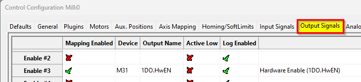
Mapping Signals to Outputs
To configure an output, follow the procedure below.
Using Outputs
Outputs 0-5 can be controlled with M-Codes. One M-Code turns an output on, and the other M-Code turns the output off. Use the table below for a reference.
|
Custom M-Codes |
Functions |
Default Output |
|
M200 |
Output 0 on |
DO-2 |
|
M201 |
Output 0 off |
|
|
M202 |
Output 1 on |
DO-3 |
|
M203 |
Output 1 off |
|
|
M204 |
Output 2 on |
DO-4 |
|
M205 |
Output 2 off |
|
|
M206 |
Output 3 on |
DO-5 |
|
M207 |
Output 3 off |
|
|
M208 |
Output 4 on |
DO-6 |
|
M209 |
Output 4 off |
|
|
M210 |
Output 5 on |
DO-7 |
|
M211 |
Output 5 off |
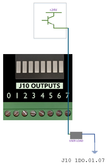
Mist and Flood Control
Mist is preconfigured in the MachPro software to be wired into Y0 and flood into Y1 output terminals.
|
Feature |
ON M-Code |
OFF M-Code |
Preconfigured Output |
|
Mist |
M7 |
M9 |
Mist On – 1DO.01.07 |
|
Flood |
M8 |
Coolant On – 1DO.01.06 |
5 Spindle Setup
Configure the VFD for the spindle motor
A VFD (Variable Frequency Drive) controls the speed of the spindle motor.
Set the VFD to match the motor’s electrical ratings:
-
Rated voltage
-
Rated current
-
Rated speed (RPM range)
You must use the values from:
-
The VFD manual
-
The spindle motor manual
Do not guess these values.
Spindle control options on the M31
The M31 controller can send the following signals to the VFD:
-
Forward rotation signal
-
Reverse rotation signal
-
0–10 V analog speed signal
If your VFD supports EtherCAT (Ethernet for Control Automation Technology):
-
The M31 can control the VFD over EtherCAT.
-
EtherCAT gives more control and access to advanced VFD functions.
Check your VFD manual to confirm EtherCAT support.
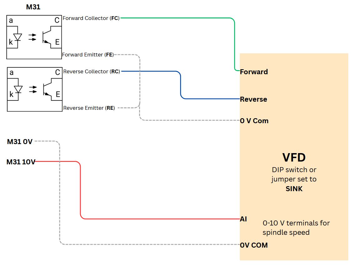
Using 0-10VDC to control the speed, and sinking outputs to control the rotation direction of the spindle
|
M31 Spindle features |
|
|
Opto-Isolator Outputs |
Forward and Reverse Open Drain / Open Collector outputs |
|
Analog Speed Signal |
0-10VDC |
|
Encoder Feedback |
Yes |
M31 to VFD Direction Control – Field Wiring Guide
This section explains how to wire the M31 motion controller to a VFD (Variable Frequency Drive) for Forward and Reverse control.
The language here uses standard sinking and sourcing terms used by field technicians.
Key facts about the M31 outputs
-
The M31 always uses sinking outputs.
-
The Forward and Reverse outputs are optocoupled.
-
Each output has an NPN sinking optocoupler to 0 V COM.
-
When an output turns ON, it connects the VFD input to 0 V COM and sinks current.
-
When an output turns OFF, the circuit is open and no current flows.
Sinking vs sourcing – basic idea
-
A sourcing device provides +24 VDC to the circuit.
-
A sinking device connects the circuit to 0 V COM to let current flow.
-
The M31 is a sinking device.
-
The VFD digital inputs usually act as sourcing inputs when configured for sinking-mode wiring.
What the VFD actually senses
-
The VFD digital inputs sense current, not the 24 VDC level.
-
The 24 VDC from the VFD is only a power source for the input circuit.
-
The VFD decides ON or OFF by checking whether current flows into the digital input.
-
If current flows, the input is active (Forward or Reverse commanded).
-
If no current flows, the input is inactive (no command).
How VFD digital inputs should be configured
Most VFDs allow different wiring modes for digital inputs.
For use with the M31:
-
Configure the VFD digital inputs for sinking-type wiring.
-
In manuals, look for terms like:
-
“Sink input”
-
“NPN input”
-
“Sinking (NPN) logic”
-
“0 V common for digital inputs”
-
“Digital inputs referenced to 0 V”
-
Avoid modes described as:
-
“Source input”
-
“PNP input”
-
“24 V common for digital inputs” (where inputs switch to +24 V)
These modes are intended for sourcing outputs, not the M31.
Role of the VFD’s 24 VDC control supply
-
The VFD normally provides a 24 VDC control supply terminal.
-
The VFD routes this 24 VDC to each digital input circuit.
-
The 24 VDC exists only to allow current to flow through the input and the M31 output.
-
The VFD’s decision is based on current presence, not on “seeing 24 VDC”.
Forward and Reverse OFF (no command)
When both M31 Forward and M31 Reverse outputs are OFF:
-
Both optocoupled outputs are open circuits.
-
No current flows from the VFD’s 24 VDC supply through the Forward input.
-
No current flows through the Reverse input.
-
The VFD reads:
-
Forward input = OFF
-
Reverse input = OFF
-
-
The VFD sees no direction command.
Forward ON – sinking current
When the M31 Forward output turns ON:
-
The VFD supplies 24 VDC to the Forward digital input circuit.
-
The VFD Forward digital input connects to the M31’s Forward Collector (FC).
-
The M31 closes the path between collector and emitter in the Forward output.
-
The emitter connects to 0 V COM.
-
Current flows:
VFD 24 VDC → M31 Forward Collector (FC)→ M31 Forward emitter (FE) → 0 V COM -
The M31 is sinking this current.
-
The VFD senses this current flow and interprets it as Forward = ON.
Reverse ON – sinking current
When the M31 Reverse output turns ON:
-
The VFD supplies 24 VDC to the Reverse digital input circuit.
-
The VFD Reverse digital input connects to the M31’s Reverse collector (RC).
-
The M31 closes the path between collector and emitter in the Reverse output.
-
The emitter connects to 0 V COM.
-
Current flows:
VFD 24 VDC → M31 Reverse Collecter (RC)→ M31 Reverse emitter (RE) → 0 V COM -
The M31 is sinking this current.
-
The VFD senses this current flow and interprets it as Reverse = ON.
Wiring checklist for field technicians
When wiring a VFD to the M31:
-
Find in the VFD manual:
-
24 VDC control supply terminal.
-
0 V COM (or “DC-”, “CM”, “COM”) terminal.
-
Digital input terminals for Forward / Run and Reverse.
-
Digital input mode settings related to sink / source / NPN / PNP.
-
-
Configure the VFD digital inputs for:
-
Sink / NPN / sinking logic mode.
-
Inputs referenced to 0 V COM.
-
-
Wire the control supply and commons:
-
Connect VFD 0 V COM to M31 FE and RE.
-
Use the VFD’s 24 VDC as the field control supply for its inputs.
-
-
Wire the direction signals:
-
Connect the VFD Forward input to the M31 Forward collector (FC) terminal.
-
Connect the VFD Reverse input to the M31 Reverse collector (RC) terminal.
-
-
Verify operation:
-
Command Forward from the M31 and confirm the VFD sees Forward ON.
-
Command Reverse from the M31 and confirm the VFD sees Reverse ON.
-
Summary
-
The M31 always uses sinking outputs for Forward and Reverse.
-
The VFD senses current, not 24 VDC level.
-
Set VFD digital inputs to sink / NPN / sinking logic mode.
-
The VFD sources 24 VDC, and the M31 sinks current to 0 V COM to signal direction.
For 0-10VDC speed control, look for Analog Inputs (AI) and 0VDC connections on the VFD.
| Analog Inputs: AI1, V1, AVI | 0 volt: AC, 0V, ACM, GND |
For direction control look for, or configure the Forward and Reverse digital control inputs on the VFD. This will also need a 0VDC connection.
| Digital Inputs: S1, FWD, S2, REV, | 0 volt: SN, SC, DCM |
This is an example connecting the M31 to a Yaskawa GA500 VFD. Please refer to the documentation for your VFD.
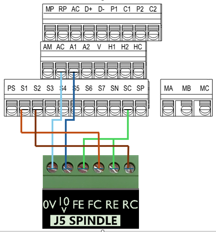
| M31 Motion Control | Yaskawa GA500 VFD |
| 0-10VDC speed control | A1 |
| 0VDC | AC |
| Forward Collector (sinking) | S1 (forward by default) |
| Reverse Collector (sinking) | S2 (reverse by default) |
| Forward Emitter | SC (common) |
| Reverse Emitter | SC (common) |
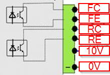
Here is a diagram showing the electronic circuit of the M31 on the Emitter and Collector signals:
Analog Spindle Voltage Adjustment
On the Systems tab of the M31 plugin, the spindle voltage can be adjusted by changing the percentage (10-200%). Most systems will not require this value to be changed. However, if the voltage is not close enough, the percentage adjustment can be calculated with the following formula:
Analog Spindle Scale % = Commanded Voltage/Actual Voltage * 100
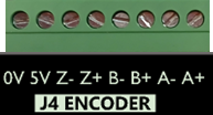
Encoder Feedback
|
Quadrature Encoder Channel |
1 |
|
Connection |
Terminal Blocks, 5V Differential |
|
Max Frequency |
1.6 MHz |
Please refer to the documentation for your VFD and spindle motor for spindle encoder connections.
EtherCat M31 Configuration
To access this configuration pull down Configuration | Plugins -> M31.

The feedback index will be the same as the motor number - in this case 3.
Set the Max Following Error very high as this is not meaningful for a spindle
Turning on the Spindle
In addition to the screen controls the spindle can also be controlled using M-codes. Use the table below as a reference.
|
M-Code |
Function |
|
M3 |
Clockwise |
|
M4 |
Counter/Clockwise |
|
M5 |
Stop |
Spindle Calibration
These instructions apply to all VFDs where the spindle is controlled through the MachPro Control Spindle tab
Why calibrate your spindle?
Does your CNC control need it? Mills and Lathes need to be calibrated while routers typically do not. The spindle speed needs to be accurate enough to meet your tooling specifications.
- The rated speeds and feeds for your tools and materials should perform as expected.
- You should have comparable performance across all your machines when running the same spindle speed.
- Accurate spindle calibration enables you to make cleaner and more accurate cuts – improving the quality of your final product.
- Scheduled preventative maintenance should include verification of the accuracy of the system, including the spindle speeds.
This documentation focuses on knee mills as a common example and is adaptable to other machines.
Prerequisites
- Your spindle needs to be configured according to your motion controller's capabilities for spindles.
- The axes need to be calibrated
- Machine zero and soft limits need to configured
- The I/O, particularly limits, need to be connected and working
Definitions
Machines often have both gears and speed controls.
The control needs to know which physical gear is engaged to control the spindle motor for the correct speed. If you use multiple gears on your machine, there will be gear change buttons on the screen, and you can also
The speed control is a set of variable diameter pulleys that provide a variable speed within each gear. We often set this to the maximum RPM. Then we use the VFD to provide the full speed range within each gear.
Set MaxRPM values for each gear
If you do not have a tachometer
Pull down Configure | Control | Spindle tab
If your machine only has one range (no pulleys or gears), then enter the minimum and maximum RPM for the spindle in the Range 1 row.
If you have multiple gears, enter the rated maximum RPM for each gear into the MaxRPM column for each gear.

If you have a tachometer
Use the steps below to set the MaxRPM:
- Set the spindle override knob on the operator control panel to 100%
- Temporarily set all MaxRPM values to twice the labeled RPM on the speed control. This is not to destroy your machine. For calibration purposes this forces the VFD to the maximum hertz output - therefore the maximum tool RPM. We use that to calibrate accurate tool RPM for normal production.
- Verify that the VFD is sending the maximum Hz to the spindle (see next section)
- Run your machine in each gear range with the temporary MaxRPM values you used above. Verify that the VFD is putting out maximum Hz. Record the actual MaxRPM values from the tachometer for each gear range.
- Enter the actual MaxRPM values that the tachometer reported in the spindle tab.

If it is not safe to run this spindle at its maximum RPM, please contact MachLabs for assistance with calibration.
Verify that the VFD is sending maximum speed commands to the spindle
You need to know that the VFD is telling the spindle motor to run at full speed. Assuming the motor is configured to run at 60 Hz, then if the VFD is sending 60 Hz, the motor is running at full speed. You just entered the MaxRPM values into the spindle config. Set your machine for one of the gears and run the spindle at the MaxRPM. You can check the VFD output two ways, and both are equally accurate:
|
|
|
|
With the enclosure door open, check the LED on the VFD. This VFD is running at P44.59% of 60 Hz = 26.754 Hz. The "P" prefix on the number indicates the number is a percentage.
|
Open a web browser and enter this IP address in the search bar 192.168.208.90. It will open a welcome page for the VFD with two buttons at the bottom. Click the Monitor button and look for the Output Frequency line. This is the same machine running at the same time, and it also reports 44.59% = 26.754 Hz. |


Adjust feedback ratios for TSpeed
The formula is MaxRPM / Maximum Motor RPM = feedback ratio
Pull down Configure | Control | Spindle tab

Check the ID plate on the spindle motor for RPM values. In this image we are running at 60 hertz; so we use the second value: 1735

MaxRPM from tachometer / Maximum Motor RPM = feedback ratio
4485 / 1735 = 2.5850144092219020172910662824207
You can paste the the full value into the spindle FeedBack Ratio field for this range, or just 2.58501
Note: the feedback ratio only adjusts the value in the TSpeed field. It does not have any effect on the actual RPM of the spindle. If the spindle speed reported by a tach does not match commanded speed, then go here: Set MaxRPM values for each gear
Operating the spindle
Use M-Codes to operate your spindle during production: M3, M4, and M5 (relevant portion of the G-Code and M-Code Reference)
You can manually control the spindle with the buttons on your operator panel.
Changing Gears
The gear ranges can be changed from the control by using M40-M45 in your G-Code file. These macros can be used to just change ranges or they can be used to automatically change gears on the machine if it has an automatic gear changer. To shift the machine range 0, run M40. M41 is range 1, M42 is range 2, and so on. You will be prompted to change the gear manually. M40 P# can also be used where # is the gear range to use.
Special situations
Overspeed a spindle motor
If you want to command your spindle motor or grinding wheel to go faster than the base frequency, command the spindle to go max RPM and use a tachometer to measure the speed. Then use the following formula to calculate your new Max Output Frequency (Hb105):
Desired Max RPM * Current Max Frequency / Current Max RPM = New Max Frequency
For example, if your Current Max Frequency is 60 and you measure the spindle runs 1030 RPM but you actually want it to go 1515 RPM, calculate your new Max Frequency as follows:
1515 * 60 / 1030=88 Hz.
Make sure to recalibrate your RPM feedback and your spindle speed as shown below.
Set a spindle to always run at maximum RPM
In some cases, a machine was originally configured to run the spindle motor at full speed, and the gears and speed controls are used to bring the RPM down to the required value. A motor running this way will always generate its maximum torque, which is very helpful when using large tools.
Pull down Configure | Control | Spindle tab

Set your MinRPM and MaxRPM for each gear to the same value.
Set your Max Spindle Motor RPM to the rated value listed on the spindle motor plate.
Leave the FeedBack Ratio values alone as they are no longer meaningful.
The spindle section of you screen can now be ignored. You will adjust your spindle speed entirely through the gears and speed control.

The rest of the spindle configuration above is not needed when it is configured to run maximum RPM.
Auxiliary Spindle MaxRPM
If your VFD is enabled as an Auxiliary spindle (under MachPro settings), set the Auxiliary Control Max RPM to the max RPM of the tool or table. Use this value both in the VFD configuration, and in the sub spindle configuration. Also see this section on sub spindle configuration

6 Advanced Options and Information
MachPro Settings
A number of advanced features can be configured in the Mach Settings such as periodic oiler control. Begin by going to Configure->Control and got to the Settings tab. Settings contains custom options for the control, including dialogue options, lube system, tool measurement/offsets, and tool changer options.
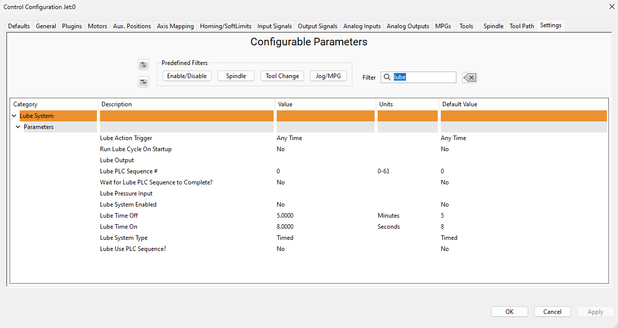
Lube System Setup
The system may require an oiler. Enable the lube system, choose an action trigger, set the lube output, set the time run time of the oiler, and the time between cycles. In the example below the lube output will turn on at 5 minute intervals for 8 seconds when it is enabled. In this system it is not enabled.
Tool Setter Setup
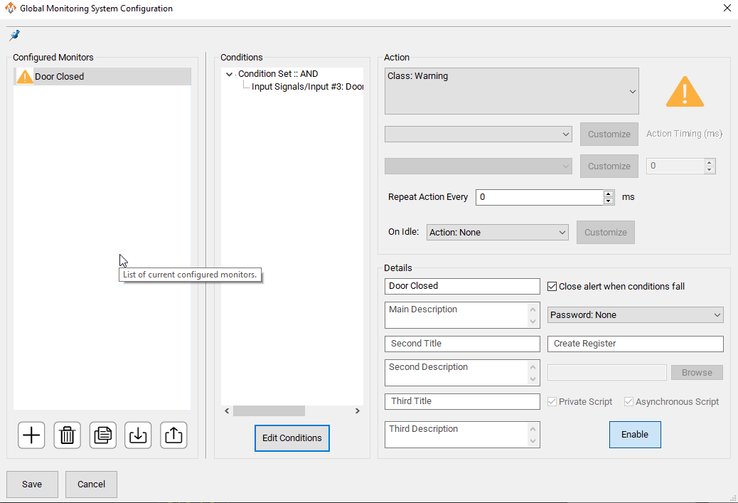
Global Monitoring System
Global Monitoring is used to setup user alerts or messages as well as to control I/O functionality based on certain conditions. To access the Global Monitoring System, go to Configure -> Plugins -> Global Monitoring System tab. The system allows the machine to watch for specified conditions, and take action when those conditions are met. For information on creating, editing, or deleting a message, visit our Global Monitoring System knowledge base online at: https://support.machmotion.com/books/knowledge-base/page/global-messaging .
7 Appendices
Signals and ports used
| Signal | M31 Junction | Input Name | Use |
J1 |
1DI.01.00 |
||
J1 |
1DI.01.01 |
||
J1 |
1DI.01.02 |
||
J1 |
1DI.01.03 |
||
J1 |
1DI.01.04 |
||
J1 |
1DI.01.05 |
||
J1 |
1DI.01.06 |
||
J1 |
1DI.01.07 |
||
J3 |
1DI.01.08 |
||
J3 |
1DI.01.09 |
||
J3 |
1DI.01.10 |
||
J3 |
1DI.01.11 |
||
J3 |
1DI.01.12 |
||
J3 |
1DI.01.13 |
||
J3 |
1DI.01.14 |
||
J3 |
1DI.01.15 |
||
J3 |
1DI.01.16 |
| Signal | M31 Junction | Output Name | Use |
J10 |
1DO.01.00 |
||
J10 |
1DO.01.01 |
||
J10 |
1DO.01.02 |
||
J10 |
1DO.01.03 |
||
J10 |
1DO.01.04 |
||
J10 |
1DO.01.05 |
||
J10 |
1DO.01.06 |
||
J10 |
1DO.01.07 |
| http://www.mach-labs.com | MachLabs Documentation | support@mach-labs.com |
The MachLabs Team
14518 County Road 7240, Newburg, MO 65550
support@mach-labs.com