
M31 Motion Control Setup Manual
{{@672}}
http://www.machmotion.com
14518 County Road 7240, Newburg, MO 65550
(573) 368-7399 • Fax (573) 341-2672
WARNING!
Improper installation of this motion controller can cause DEATH, INJURY or serious PROPERTY DAMAGE. Do not attempt to install this controller until thoroughly reading and understanding this manual.
1 Introduction
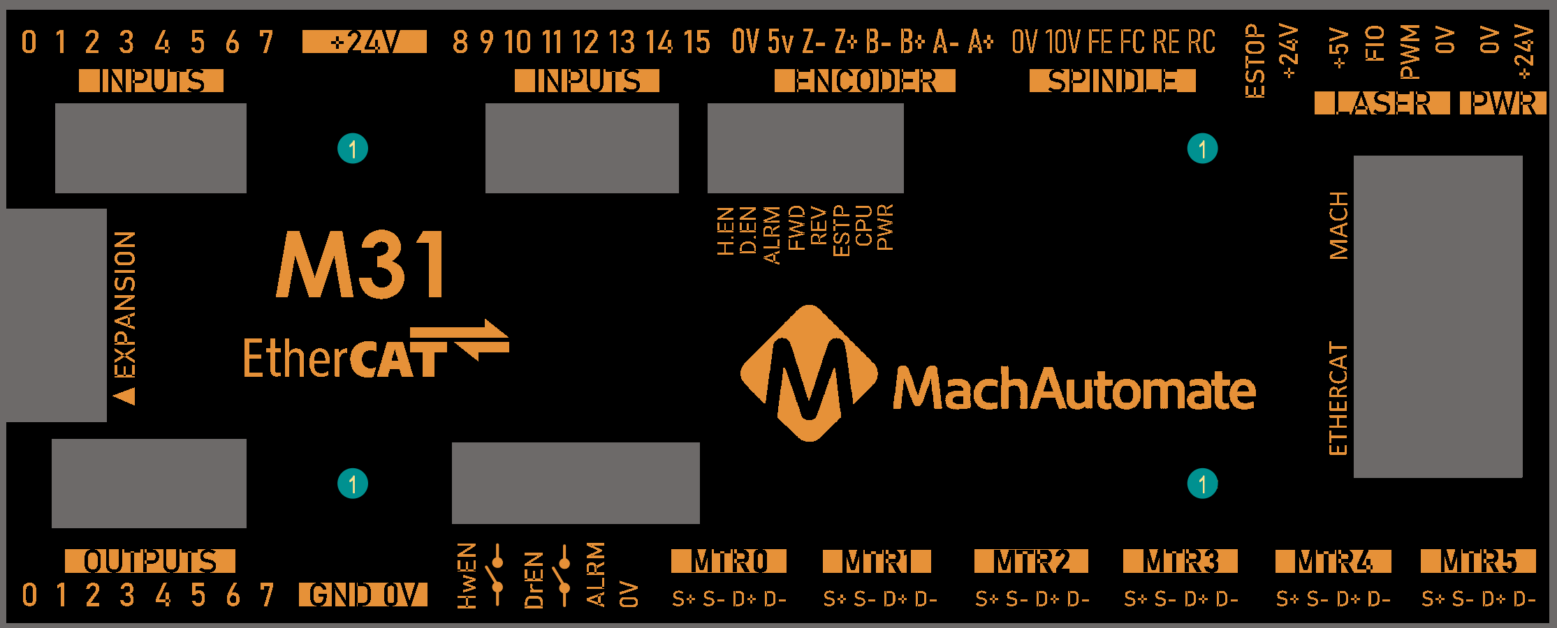
1.1 Reference Diagram
Use the diagram below as a reference throughout the manual.
1.2 Specifications
Below are the specifications for the M31 motion controller.
|
Item |
Specification |
|
Input Power |
24VDC |
|
|
Do NOT connect DC voltage greater than 48V, or any AC voltage to any part of the M31 motion controller. It could cause serious damage to the controller. |
|
Max Power Consumption |
48W |
|
|
|
|
Stepper Channels |
4 or 6 depending on the model |
|
Step and Direction Axis Control |
5V Single Ended and Differential |
|
Connection |
Terminal Blocks |
|
Max Pulse Speed |
1.6 MHz |
|
|
|
|
Ethercat Network |
|
|
Device Types |
Servo Motors, Stepper Motors, VFDs, I/O Modules, etc |
|
Max Devices |
10 |
|
Max Motors |
4 or 6 depending on model |
|
|
|
|
Quadrature Encoder Channel |
1 |
|
Connection |
Terminal Blocks, 5V Differential |
|
Max Frequency |
1.6 MHz |
|
|
|
|
Spindle |
1 |
|
Opto-Isolator Outputs |
Forward and Reverse Open Drain / Open Collector outputs |
|
Analog Speed Signal |
0-10VDC |
|
Encoder Feedback |
Yes |
|
|
|
|
Digital Outputs |
8 |
|
Voltage |
16 - 24VDC |
|
Max Current |
250mA |
|
|
|
|
Inputs |
16 (PNP Sourcing) |
|
Voltage |
16-24VDC |
|
Input Current Range |
3 - 6mA |
|
Isolated |
Yes |
|
|
|
|
Enable Circuit |
2 |
|
Hardware Enable |
Relay Dry Contacts, 5V Enable or 24V Enable |
|
Drive Enable |
Relay Dry Contacts |
|
|
|
|
Emergency Stop Circuit |
Normally Closed Connection |
|
|
|
|
Ethernet Port |
10/100 MHz |
|
|
|
|
Dimensions |
8.32"(L) X 5.75"(W) X _______________________________ (H) |
|
Optimal Temperature Range |
32° to 100°F (0° to 38°C) |
|
Humidity |
30% - 60% RH |
1.3 Status LEDs
All LEDs are single color and they are either on or off.
| LED | ON | OFF |
| Power | green - M31 is powered | No Power |
| CPU | blue - M31 CPU is active | CPU is not enabled |
| E-Etop | red - E-Stop pressed, or the E-Stop circuit is incomplete | E-Stop is not active |
| Hardware enable | orange | No hardware enable signal |
| Drive enable | orange | No drive enable signal |
| Spindle fwd | green when spinning forward | |
| Spindle rev | green when spinning in reverse | |
| Drive alarm | red - one or more drives are in alarm state | All drives report good |
1.4 Tools Required
A small, flat head screwdriver is needed for the I/O terminals.
The Phoenix connectors on the M31 should be torqued between 4.4 and 5.3 lb/in.
1.5 Hardware Startup
To power the M31, you must supply 24VDC to the power connection located at the top right of the board as shown below. The LED labeled PWR will be green when 24VDC is supplied.
1.8 Software Startup
On the desktop of your control, there is a MachV shortcut for your machine type. Below is an example of the MachV shortcut.
![]()
There is also a shortcut for MachV Loader. This allows any of the profiles to be loaded from one location. Double clicking on the MachV Loader shortcut opens the following window:

After double clicking on a profile or opening a profile from MachV Loader, a window will come up asking to Press Cycle Start to Enable Mach and Home All Axes. Select [Cancel] since motion is not yet possible.

On subsequent startups, once motion and limit switches are set, press [Cycle Start] and the control will enable and home all axes. This prompt can be turned off in the machmotion plugin if desired.
2 Axis Setup
2.1 M31
All of the drives and external I/O will be wired into the M31.
2.2 Enabling Axes
After the drives are connected to the M31, open up the motion software, and enable the axes as follows:
Note: This may already be setup depending on your system.
 Press [Apply] to save any changes.
- Next, select the Axis Mapping tab as pictured below. Associate the enabled motors to the applicable axis. In this example, Motor0 is the X master, Motor1 is the Y master, and Motor2 is the Z master. No slave axes are configured on this system.

- Press [Apply] and [OK] to save and close.
The system should now be able to jog, however,....
WARNING
The machine can be crashed very easily. The axes need to be calibrated and the limits set up.
2.3 Axis Calibration
For each axis to move the correct distance, the axes need to be calibrated. If all of the hardware is new, use the machine specifications and the automatic calibration wizard. This is the best calibration method. If your hardware is not new, and you are not getting the accuracy you need, then use the manual calibration wizard. This will provide very good accuracy - especially if you calibrate over greater distances of travel. Use the longest distance that you can accurately measure on each axis.
Go to Configure-> Plugins -> Machine Calibration.
Select the type of configuration you would like to perform from the window:
- Manual; Calculate the steps per by comparing distance traveled vs. distance commanded. See the next section for instructions.
- Automatic; Calibrate motors using specifications of your motor type. Continue for instructions.
2.3.1 Automatic Calibration
- Select the drive type of the axis being configured.
- Select the max motor RPM.
- Verify the correct drive ratio.
Drive Ratio M31 Drive Type 1 Teco 8 Mitsubishi 64 Yaskawa 1 Stepper EtherCat Table 3 - Default Drive Ratio Value
- Choose the machine configuration for the axis from the following three options.
- Enter the ball screw pitch
- Enter the ball screw pulley # teeth and motor pulley # teeth
Note: If the system has a pulley ratio and a gear box use this equation to get the total gear ratio: [Gear Box Ratio] x [Pulley Ratio] = [Total Gear Ratio] Ex: [10:1 Gear Box] x [30 Motor Pulley Teeth/15 Ball Screw Pulley Teeth] = [10] x [30/15] = [20 Total Gear Ratio](20 Motor Pulley Teeth, 1 Ball Screw Pulley Teeth)
- Enter pinion diameter
- Enter the gearing ratio between the shaft and the motor
- Enter number of teeth on pinion
- Enter the rack pitch
- Enter the gearing ratio between the shaft and the motor
- Ball Screw
- Rack and Pinion – Pinion Diameter
- Rack and Pinion – Rack Pitch
- Select the axis to calibrate.
- Press the [Calculate] button.
- Choose [Accept] or [Ignore] to save or discard the changes.
- Repeat starting at step 2 for each additional axis.
- Press [OK] and restart the software to save the calibration settings.

2.3.2 Manual Calibration

Select Manual Calibration from the Machine Calibration Selector menu.
- Select the axis to calibrate.
- Select either Jog Distance or Commanded Distance.
- Typically commanded distance is used. This is where you enter the distance you want it to move and then record how far it actually moved. Use the longest distance you can accurately measure.
- Enable the system and either press [Move] or [Record Jog].
- For Jog Distance mode, manually jog the axis a distance that can be accurately measured. Use the longest distance you can accurately measure.
- Measure how far the axis moved.
- Enter in the distance the axis moved and press [Submit].
- Choose [Accept] or [Ignore] to save or discard the changes.
- Repeat this procedure until the axis is within the required accuracy.
If you want to adjust your velocity, select Configure on the top menu bar, then Control. Select the Motors tab as shown below.
In the right pane, click on the motor you want to set up (Click the word to highlight and select the axis). The checkbox is for enabling/disabling the motor). The selected motor’s parameters will be loaded and the velocity or acceleration settings can be adjusted. For stepper motors, max acceleration is typically 15-20 if in standard units. For servo motors, a value of 30-40 is typically best. The max velocity is limited by several factors, including the motor. If you want an axis rapid speed to be limited or lowered, adjust the velocity for that motor to the max speed you want the rapid to be.
Press [Apply] before clicking on another motor or closing out the Mach Configuration window. NOTE: If you change the counts per unit, the velocity and acceleration values will adjust accordingly. If you do not want them to change, type in the current values shown. Verify by clicking another motor and then coming back to the adjusted motor.
WARNING
No limits have been set up. DEATH, INJURY or serious PROPERTY DAMAGE can occur if the system is not operated carefully.
Limits and homing setup will be completed in section 4
2.4 Backlash Software Compensation
If there is more than .003" of backlash there will likely be accuracy, motion, and surface finish issues. If your CNC system uses scales to provide direct position feedback, it will continue to move the axes to reach the commanded position. However, there may still be motion and surface finish problems. The best solution is to maintain the mechanics with a regular preventative maintenance plan, and to repair parts that are outside of acceptable specifications.
The M31 provides software backlash compensation. To calculate the machine’s backlash, follow the steps below.
- Use the MDI window to enter G-Code and move each axis.
- Move an axis in one direction farther than the maximum possible backlash.
- Mount a dial indicator and zero it.
- Move the axis again in the same direction for a specific distance (it doesn’t matter how far).
- Move the axis backwards the same distance.
- The distance your dial indicator is off from zero is that axis' backlash value.
- Backlash is configured in the HiCON plugin. On the menu bar, go to Configure->Plugins and select the HiCON plugin.
- Select the desired motor tab and enter the values (see explanation below). Select [OK] to save settings.
Backlash – This field sets the backlash amount in inches or millimeters, depending on the setup units. Start by entering half of the backlash value, test and adjust.
Backlash Speed % – This field adjusts the maximum acceleration that the backlash counts can be applied. The M31 takes the max acceleration of the motor and multiplies it by this percentage. Valid values are 10-400 (0.1 to 4 times max acceleration). A common value is 20%.

WARNING
Do not leave the backlash speed zero if you enter in a backlash distance. The M31 will not function.
For best performance, backlash should be less than .0015 inches.
2.5 Reversing Direction
If a motor moves the wrong direction, it can be reversed in the software.
- From the main menu bar, click Configure->Control and then select the Motors tab to display the following:

- Select the motor (not the checkbox) from the list on the Right.
- Check the Reverse? box if the motor direction needs to be reversed.
- After making all the changes, press [OK].

The motor will now move the opposite direction than it did before. If the homing direction was already set, it will need to be reversed as well. (see the homing section)section).
NOTE: If you are needing to reverse direction on an axis with a slave motor, you may need to change the direction for both the master and slave axis.
2.6 Slaving a Motor
To configure a motor as a slave:
- From the main menu bar, select Configure->Control and then select the Axis Mapping tab.
- Select the motor from the
dropdowndrop-down menu for the axis that the motor will be slaved to. Each enabled axis must have one master and up to 5 slave motors. For example, the configuration below is used to slave Motor3 to Motor0 on the X axis.
- Press [OK] to save changes.

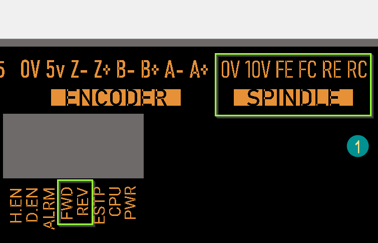
3 Spindle Setup
3.1 Configuration for 0-10V operation
The M31 spindle control consists of a 0-10V analog signal for spindle speed and two outputs for direction: Forward and Reverse Open Drain / Open Collector outputs. There are two LEDs on the M31 that indicate FWD or REV.
3.1 Wiring a Spindle
3.1.1 VFD from MachMotion
The process for setting up a VFD from MachMotion is extremely simple. Simply plug the control cable into the Spindle Control RJ45 jack located on the bottom row of the large RJ45 block.

3.1.2 VFD Other Than from MachMotion
Any VFD can be wired into the Spindle Control RJ45 jack by cutting the end off of a CAT5 cable and wiring the loose ends to the VFD according the following pin out.
|
Function |
Analog 0-10VDC |
CW Relay |
CW Relay |
Drive Enable |
GND |
N/C |
CCW Relay |
CCW Relay |
|
RJ45 Pins |
1 |
2 |
3 |
4 |
5 |
6 |
7 |
8 |
|
Colors |
White & Orange |
Orange |
White & Green |
Blue |
White & Blue |
Green |
White & Brown |
Brown |
3.1.3 No VFD
If the system does not use a VFD to control the spindle, a FWD/REV Contactor circuit can be used and is available from MachMotion. Wire the spindle according to the diagram below. Notice that 24V is wired to the CW and CCW relay contacts on the top row of the green terminals.

3.2 Spindle Calibration
4 Limits and Homing Setup
4.1 General Info
Note: See section 5 for more specifics on wiring inputs such as limit/home switches
4.2 Wiring Switches
The M31 motion controller has up to 16 inputs that can be used for the limit and home switches. To maximize the number of inputs available for other functions, wire multiple switches for the same axis in series as shown below.

Note: For the highest level of safety, wire the limit switches Normally Closed.
|
Motor |
M31 Input |
|
0 |
X1 |
|
1 |
X2 |
|
2 |
X3 |
|
3 |
X4 |
|
4 |
X5 |
|
5 |
X6 |
Table 6 Input Numbers
To set up and wire 24V limit/home switches, follow the steps outlined below.
PickSelect, or install, two limit switches closest to theendaxis'ofhard limits. Place them so that theaxis’limitsmaximumwillandtripminimumbeforetravel.the axis hits a hard limit.- Wire the two switches normally closed and in series. If either limit is tripped, the circuit will open and the motion will stop.
- Wire
the remainingone side of the first switch to C0+ from the M31 motion controller. - Wire the
remainingother side of the limit/home switch into the correct input(see Table 6)depending on which axis is being wired. - On the menu bar at the top of the screen select Configure->Control. Select the Input Signals tab.
- Scroll down through the list until you find the different motor sections (Home, -- , and ++). The example image below shows the inputs scrolled down to the motor home section. Further down is ++ and --.
- Enable the limit and home switches by clicking the red [X] by the signal to make it a green check.
- Note: Each motor has three signals, the max travel (motor ++), the min travel (motor --), and the home (motor home). All three must be enabled and set to the correct device and input name for everything to work correctly using the wiring description above.
- Set the device and input name to the desired input. All input signals use [P11] and the input name corresponds to the X number it is wired to (Ex. An input wired into X3 will be [P11] Input3).
- Set up the active low checkbox to a green check for a normally closed switch.
- Note: Under the active low column the active state can be changed by clicking on the [X] or check mark. If the limit switches are normally open the red X should be used. However, this is not recommended as it is not as safe.
- When the limit and home switches for each motor are completely configured, press [Apply] and then [OK].

In the example above, motor 0, 1, and 2 home switches are enabled. All of them are wired normally closed. The device and input name for motor 0 is HiCON [P11] Input1 (X1). Since the switches for each motor are wired in series, the motor ++ and motor -- signals lower down in the list would also have the same corresponding device and input names. Manually trigger each limit switch and make sure they disable Mach before continuing.
4.3 Homing Setup
WARNING
If the limit switches are not set up correctly or if an axis moves in the opposite direction of the home switch, the machine could crash. Make sure to keep a hand on the Emergency Stop button the first time the machine homes.

- Select the direction each axis should home toward (positive or negative).
- Configure the home order, with 1 being first, 2 being second, etc…
- Set the homing speed of the axis by changing the percentage under the Speed % (20% is maximum for most systems for optimal performance. Slower speeds can prevent over-travel. Jogging in rapid or faster speeds to move maching closer to home position prior to homing can save time).
- Ensure Home In Place column is a red X. If green check mark, click on it to change to red X. If it is a green checkmark it will not move to the home switches.
- Press [OK] to save changes.
Homing on the machine should now be completely set up. Home each axis individually to verify the configuration. Press the [Home All] button again to make sure that everything works correctly.
4.3.1 Homing Slave Axis
There are 2 configuration options:
Homing with Home/Limit switch on the Master:
- In the MachV software go to Configure=>Control=>Axis Mapping
- Select which motor is the slave under Slave 1
- Configure=>Plugins=>HiCON
- Select the motor that you want to be the master and uncheck the Independent Master-Slave Home and make sure that the index pulse is unchecked.
- Select the motor that you want to be the slave and uncheck the Independent Master-Slave Home and make sure that the index pulse is unchecked.
- Configure=>Control=>Input Signals
- Make sure that the slave axis home switch, Motor - and Motor + are disabled
Homing with Home/Limit switch on Master and Slave:
- In the MachV software go to Configure=>Control=>Axis Mapping
- Select which motor is the slave under Slave 1
- Configure=>Control=>Inputs Signals
- Make sure that the Slave axis home switch, Motor - and Motor + are Enabled.
- Configure=>Plugins=>HiCON
- Select the motor that you want to be the master and check the Independent Master-Slave Home and make sure that the index pulse is unchecked.
- Select the motor that you want to be the slave and check the Independent Master-Slave Home and make sure that the index pulse is unchecked.
- Set Slave Misalignment value if needed to "square" the gantry
Troubleshooting:
If there are motion issues with the homing, it is likely the axis designation does not match the homing switch designation. In other words, the homing switch assigned to the master axis is likely actually on the slave axis.
-
- After touching off the switches, if one of sides of the gantry continues to travel, "dragging" the other side along with it, would be an example of such motion issue caused by "swapped" configuration of switch assignments.
4.4 Soft Limits Setup
With machine homed correctly and soft limits set, the machine will not hit a physical limit switch. If at any time a command is made for the machine to move outside of the soft limits (while they are enabled), an error will appear in the status line and motion will stop. To set up the soft limits, follow the procedure outlined below.
- Home the machine.
- Select to view Machine Coordinates on the Locked screen view so that the DRO’s are orange.
-
- Jog the machine to the maximum distance from the homing switches.
- Note: Make sure to stay inside the physical limit switches. If the machine is jogged outside of the limit switches, it completely defeats the purpose of soft limits.
- Record the machine coordinates at the end of the travel.
- Open the menu bar and click Configure->Control and select the Homing/SoftLimits tab as previously shown.
- Enable soft limits on each desired axis by setting the Soft Enable column to a green check mark, and enter in the recorded values.
- Note: If the value is positive, place it into the Soft Max limit and set the Soft Min limit to zero. Otherwise, with a negative value, set the Soft Max to zero and the Soft Min to the recorded value.
- Press [OK] to save changes. Test the soft limits by jogging the axes to maximum amounts in all directions.

Note: When loading a G-code file, the tool path display will show the soft limits as dashed lines. If any part of the tool path renders outside the soft limits, check your file.
5 Input Setup
5.1 Generic Inputs
There are 16 inputs on the M31 (15 available for your use as X0 is reserved for the drive fault signal). These can be used for limit/home switches, tool changer signals, alarm conditions, or most anything else.
Note: To learn how to set up limit switches, go to Setting up Limits and Homing.

Each input has an LED that shows the current state of the input. Both the LED and input are labeled with the input name. The inputs run from X0, up to X15. If the LED is on, then the input is activated. Different configurations can be selected for each input by using the jumpers near the bottom right of M31. Each jumper corresponds to an input. For example, the jumper labeled X10 corresponds to the input terminal abeled X10 and the LED X10.

There are 3 jumper positions. Position 1 is the jumper in the lower position across the bottom 2 pins. Position 2 is the jumper in the upper position across the top 2 pins. Position 3 is the jumper removed (can be placed on just the top or bottom pin with the other side of jumper not connected to any pin so that you can easily use it again if needed).

The figure below shows the schematic of an input where S is the input number. The jumper only shows the three pins used for that input.

WARNING
Input X0 is configured as drive fault by default.
DO NOT connect anything to X0. It could damage your drives or M31 motion controller.
5.2 Wiring Inputs
There are helpful videos on our youtube channel:
https://www.youtube.com/watch?v=wVQ1OE3PQDE
https://www.youtube.com/watch?v=wgD4nAkKHLQ
5.2.1 Standard 24V Inputs
For a standard 24V input, place the jumper on the bottom two pins. Next, connect C0+ to 24V and C0- to GND on the input terminals (should already be jumper in place from factory for this). In the example below, all the inputs are set up as standard 24V inputs.

Then connect the input to the input terminal on the middle row (X1, X2, etc.). See the diagram below.

To activate the input, 24V must be supplied to the input. A floating signal or a ground will not turn on the input. The LED corresponding to the input will turn on brightly when the input is activated.
5.2.2 Sinking Inputs (NPN)
For most NPN proxies place the jumper on the top two pins. Then connect the signal into the corresponding input. See the example below.

If the proxy has an internal pull-up resistor, depending on its size, it could require the jumper to be completely removed. Use a 3.9k ohm resistor and connect it between XSL and C0+.
Below is an example of a 24V NPN proxy with an internal pull-up resistor. The jumper on the M31 must be completely removed for this to work.

5.2.3 Sourcing Inputs (PNP)
For PNP proxies place the jumper on the bottom two pins. Then connect the signal into the corresponding input.

5.3 Configuring Inputs

- Enable the desired input by clicking on the red “X”. If it is a green check mark, it is already enabled.
- Set the device and input name to the desired input.
Note: Device will be HiCON and Input Name will be [P11] Input X number (X4 would be Input 4) - To change when the input is active, click on the Active Low A green check mark means that the input is active low and a red X means that the input is active high.
- Press [OK] to save changes. The inputs are now set up.

5.4 Supplemental Information: Input Circuit
The image below shows the schematic of an input where S is the input number. The jumper pin 3 is on the top and the pin 1 is on the bottom.

6 Output Setup
6.1 Generic Outputs
The M31 has 8 logic outputs that can be used for any low current application. They are located on the terminal block of the board as shown below (note-the output terminals are likely black in color for your board).

The outputs and associated LEDs are labeled Y0 through Y7. If the LED is on, the output is activated.
6.2 Wiring Outputs
There are two separate commons for the outputs. The common C1+ is for outputs Y0-Y3 and C2+ is for Y4-Y7. Each common can take 7-48VDC. If the outputs being used are using the voltage supply from M31, each output can only supply 125mA. However, if they are supplied using a separate voltage source, each output can source up to 250mA. For standard operation the output commons are jumpered to 24V on the M31. At that point simply connect the load between the output and GND. See the figure below.
6.3 Configuring Outputs
To configure an output, follow the procedure below.

6.4 Using Outputs
Outputs 0-5 can be controlled with M-Codes. One M-Code turns an output on, and the other M-Code turns the output off. Use the table below for a reference.
|
Custom M-Codes |
Functions |
Default Output |
|
M200 |
Output 0 on |
Y2 |
|
M201 |
Output 0 off |
|
|
M202 |
Output 1 on |
Y3 |
|
M203 |
Output 1 off |
|
|
M204 |
Output 2 on |
Y4 |
|
M205 |
Output 2 off |
|
|
M206 |
Output 3 on |
Y5 |
|
M207 |
Output 3 off |
|
|
M208 |
Output 4 on |
Y6 |
|
M209 |
Output 4 off |
|
|
M210 |
Output 5 on |
Y7 |
|
M211 |
Output 5 off |
6.5 Mist and Flood Control
Mist is already preconfigured in the software to be wired into Y0 and flood into Y1 output terminals.
|
Feature |
ON M-Code |
OFF M-Code |
Preconfigured Output |
|
Mist |
M7 |
M9 |
Mist On – [P11 Output0] |
|
Flood |
M8 |
Coolant On – [P11 Output1] |
7 Advanced Options and Information
7.1 MachMotion Plugin
A number of advanced features can be accessed and configured in the MachMotion plugin such as periodic oiler control and custom user messages (Global Monitoring System). Begin by going to Configure->Plugins to open the MachMotion plugin.

The Machine Parameters tab contains custom options for the control, including dialogue options, lube system, tool measurement/offsets, and tool changer options.
7.1.1 Lube System Setup
The system may require an oiler. Enable the lube system, choose an action trigger, set the lube output, set the time run time of the oiler, and the time between cycles. In the example below the lube output will turn on when the spindle is running for 10 seconds every 15 minutes.

7.1.2 Tool Setter Setup
Auto tool setters use a "Probe input". G31, G31.1 ect. Configure this in the Input Signals section under Probe(G31), Probe 1(G31.1) ect.
To add a new setter, press "Add new" and then fill out the options and run through the Height and Z position Wizards.
On the Tools tab, click on the Tool Setters button. Then choose, "Add new".

You can have multiple tool setters, both manual and auto.

7.2 Global Monitoring System
Global Monitoring is used to setup user alerts or messages as well as to control I/O functionality based on certain conditions. To access the Global Monitoring System, go to Configure -> Plugins -> MachMotion and select the Global Monitoring System tab. The system allows the machine to watch for specified conditions, and take action when those conditions are met. For information on creating, editing, or deleting a message, visit our Global Monitoring System knowledge base online at: https://support.machmotion.com/books/knowledge-base/page/global-messaging.
7.3 Emergency Stop (E-stop Circuit)
The emergency stop connector is located right below the power connector on the M31. When the emergency stop terminals are connected together, the red E-Stop LED turns on and the controller can then enable.

Note: Nothing will work on the M31 motion controller unless the Emergency Stop terminals are connected together!
Our control has an E-Stop button wired into this terminal on the M31. If you would like to add additional E-Stop buttons you can wire them in series to the existing E-Stop circuit.
DANGER
If wiring an additional E-Stop button to the M31 board, make sure that there is NO voltage required for that button. However, if voltage is needed it will be required to wire the E-Stop button into a relay input and relay output with E-Stop circuit. An electrician should be consulted for further assistance.
Emergency stop input is set up inside the software by setting the E-Stop Input Signal to HiCON [P14] Input5 and should be pre-configured for you. When it is set up correctly, any time the emergency stop terminals are disconnected, the system will be disabled.

7.4 Motors
To set up the motors, the drives must be connected to the controller, the M31 controller must be configured, and the control software must be set up as defined below.
7.4.1 Connecting Drives
The M31 motion controller uses step and direction to control the axes. It can use differential or single-ended outputs. For differential outputs there are two signals for step (step + and step -) and two signals for direction (direction + and direction -). For single-ended there is only one signal for both step and direction. All MachMotion products use differential outputs.
7.4.2 Differential Control
Most systems use differential step and direction. The step and direction outputs are located on the bottom row of RJ1, the large RJ45 jack block. See the diagram below.

The pinout for the RJ45 jacks is shown below.
|
Function |
Reserved |
Drive Error |
Direction + |
Drive Enable |
GND |
Direction - |
Step + |
Step - |
|
RJ45 Pins |
1 |
2 |
3 |
4 |
5 |
6 |
7 |
8 |
|
Colors |
White & Orange |
Orange |
White & Green |
Blue |
White & Blue |
Green |
White & Brown |
Brown |
Any drive from MachMotion can be plugged directly into the motor control RJ45 jacks.
7.4.3 Single-Ended Control
To use single-ended control use the terminals on TB1 (the large green input terminal block). The top row is for the direction signals and the middle row is for the step signals. The first letter on each terminal is the axis name and the second letter is the function (D for direction and S for step). See the picture below.

With the drives connected it is time to connect the encoder feedback. Skip the next section if the system does not have encoder feedback or if it is not going to be set up at this time.
7.4.4 Encoder Feedback
The encoder feedback inputs are located on the top of RJ1. The encoder signal for each axis is directly above the control signal. See the diagram below.

The M31uses a 5V encoder signal. See the pinout below.
|
Function |
A+ |
A- |
B+ |
5V |
GND |
B- |
I+ |
I- |
|
RJ45 Pins |
1 |
2 |
3 |
4 |
5 |
6 |
7 |
8 |
|
Colors |
White & Orange |
Orange |
White & Green |
Blue |
White & Blue |
Green |
White & Brown |
Brown |
7.5 Axis Mapping and Slaving a Motor
To map motors to axes or to configure a motor as a slave, follow the steps outlined below.
- Click Configure->Control on the main menu bar and select the Axis Mapping
- Each enabled axis must have one master motor and up to five slave motors
- Press [OK] and then restart the software

7.6 Spindle
For most systems from MachMotion, the following is not needed. However, to adjust spindle the spindle voltage, use encoder feedback, or connect your devices not purchased from MachMotion, use the following section for additional information.
7.6.1 Spindle Voltage Adjustment
On the Systems tab of the HiCON plugin, the spindle voltage can be adjusted by changing the percentage (10-200%). Most systems will not require this value to be changed. However, if the voltage is not close enough, the percentage adjustment can be calculated with the following formula:
Analog Spindle Scale % = Commanded Voltage/Actual Voltage*100
7.6.2 RPM Feedback
If the spindle has encoder feedback, set up the Threading section of the HiCON Plugin. Set the RPM Sync Source to Encoder, the RPM Sync Index to 6, and the RPM Counts/Rev to the number of encoder pulses per revolution.

7.6.3 Turning on the Spindle
In addition to the screen controls the spindle can also be controlled using M-codes. Use the table below as a reference.
|
M-Code |
Function |
|
M3 |
Clockwise |
|
M4 |
Counter/Clockwise |
|
M5 |
Stop |
Table 11 Spindle M-Codes
8 Appendices
8.1 Default Factory Settings
These are default settings but are not required for the system to function correctly.
|
Signal |
Mapping Enabled |
Device |
Input Name |
Active Low |
|
Input #0 |
✔ |
HiCON |
[P11] Input0 |
X |
|
Motor 0 Home |
✔ |
HiCON |
[P11] Input1 |
✔ |
|
Motor 1 Home |
✔ |
HiCON |
[P11] Input2 |
✔ |
|
Motor 2 Home |
✔ |
HiCON |
[P11] Input3 |
✔ |
|
Motor 0 ++ |
✔ |
HiCON |
[P11] Input1 |
✔ |
|
Motor 1 ++ |
✔ |
HiCON |
[P11] Input2 |
✔ |
|
Motor 2 ++ |
✔ |
HiCON |
[P11] Input3 |
✔ |
|
Motor 0 – – |
✔ |
HiCON |
[P11] Input1 |
✔ |
|
Motor 1 – – |
✔ |
HiCON |
[P11] Input2 |
✔ |
|
Motor 2 – – |
✔ |
HiCON |
[P11] Input3 |
✔ |
|
E-Stop |
✔ |
HiCON |
[P14] Input5 |
✔ |
|
Signal |
Mapping Enabled |
Device |
Input Name |
Active Low |
|
Output #0 |
✔ |
HiCON |
[P11] Output2 |
X |
|
Output #1 |
✔ |
HiCON |
[P11] Output3 |
X |
|
Output #2 |
✔ |
HiCON |
[P11] Output4 |
X |
|
Output #3 |
✔ |
HiCON |
[P11] Output5 |
X |
|
Output #4 |
✔ |
HiCON |
[P11] Output6 |
X |
|
Output #5 |
✔ |
HiCON |
[P11] Output7 |
X |
|
Spindle FWD |
✔ |
HiCON |
[P14] Output6 |
X |
|
Spindle REV |
✔ |
HiCON |
[P14] Output7 |
X |
|
Coolant On |
✔ |
HiCON |
[P11] Output0 |
X |
|
Mist On |
✔ |
HiCON |
[P11] Output1 |
X |
8.2 Enable Circuit
The M31 has a hardware enable and a drive enable circuit. However, before they will work, the emergency stop circuit must be set up. Use the table below as a quick reference for the different signals.
|
MachV Name |
Signal Name |
Device |
Name |
Active |
Input / Output |
|
Hardware Enable |
--- |
HiCON |
[P14]Output0 |
--- |
Output |
|
Drive Enable |
--- |
HiCON |
[P14]Output1 |
--- |
Output |
|
E-Stop |
E-Stop |
HiCON |
[P14]Input5 |
Low (Green Check) |
Input |
8.3 M31 Drawing
There is a PDF of the following drawing attached to this document (online) so you can print and use as a template if needed.

8.4 M31 Case Mount Drawing
There is a PDF of the following drawing attached to this document (online) so you can print and use as a template if needed.

{{@687# This section covers warranty!}}{{@677}}