MachPro Waterjet Setup Manual
{{@2007#bkmrk--1}}
Connect and map the inputs and outputs
The M31 manual has two sections that need to be completed before setting up the jets and abrasive
Every waterjet will need most of following signals for each jet. Map each of the ones you need to the correct output.
| Name | Function |
| Jet Abrasive Output(s) | Turns on and off abrasive for the corresponding jet. |
| Jet Pump Output | This turns on the actual intensifier pump. If using a PLC this should trigger the PLC to start the intensifier. Often called Intensifier on. |
| Jet High Pressure Output(s) | Turns on and off high pressure for the corresponding jet. Also called things like UHP On, high pressure on. |
| Jet Pressure Output(s) | Turns on and off the actual jet. Often called Water On or Jet On. |
pump 01.03 = intensifier on
jets on turns on jet pressure ?= jet on? and abrasive on
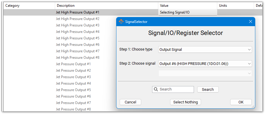
Where is high pressure? 01.06
Setup the first jet
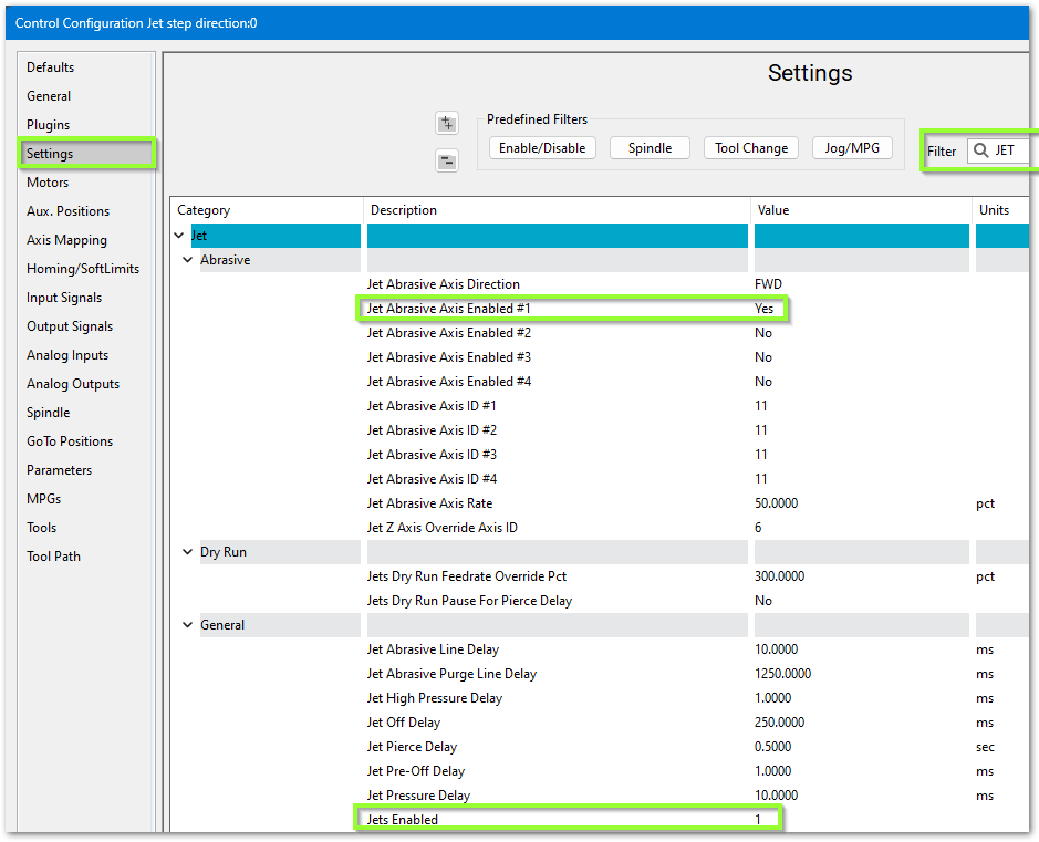
- Pull down Configure -> Control -> Settings tab
- In the upper right corner, filter the settings for jet
- Set Jets Enabled to 1
- If you are using abrasive then set Jet Abrasive Axis Enabled #1 to Yes

- [match the needed settings to the software signal outputs]
 You may try setting the Jet Abrasive Purge Line Delay at 1250 ms which allows the abrasive to stop flowing just before the water turns off. Also set the Jet Off Delay to 250 ms which gives us a slight pause after the water turns off and before it starts moving to the next cut.
IO Setup
[O setup logical I/O in sim for one complete jet, O map software signals to I/O, O use settings connect to mapped signals. ? extra level of meta signals/settings?
Virtually every waterjet will need some of following signals. Map each of the ones you need to the correct output.
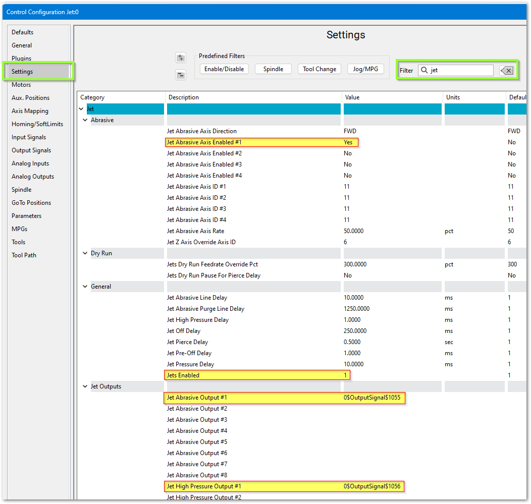
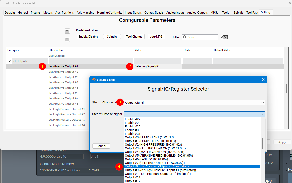
For example, Jet Pressure Output #1 here is set to Output #6, which is an EtherCAT digital output.
Some waterjets may have some of these more advanced IO. This is more for when the intensifier is controlled inside the MachPro PLC.
The main sequence to power on the intensifier is as follows:
- Turn on water (Filtered water shutoff valve). This allows water to go to the intensifier.
- Turn on the Bleeddown Valve to prepare the intensifier to run.
- Turn on Boost / Water Inlet Motor. This brings the incoming water up to a low PSI (like 50PSI)
- Wait until INLET WATER PRESSURE SHUTDOWN is active so we know the water pressure is above the base PSI. Often 3-5 seconds to build pressure.
- Turn on the intensifier. Turn on Cooling Water Shutoff valve to keep the water cold.
To turn off the intensifier, the following sequence is used:
- Turn off Intensifier and Cooling Water Shutoff.
- Turn on Bleeddown Valve to let the pressure out of the lines.
- Turn off the boost motor and the water.
You may have inputs for HYDRAULIC OIL OVERTEMP. Configure a GMS to monitor this signal as follows:

Some waterjets have a servo controlled Abrasive. For that use these settings:

------------------------ start imported from advanced features --------------------
WaterJet Setup
Configure the number of jets you need and your default delays. Pull down Configure -> Control - Settings.
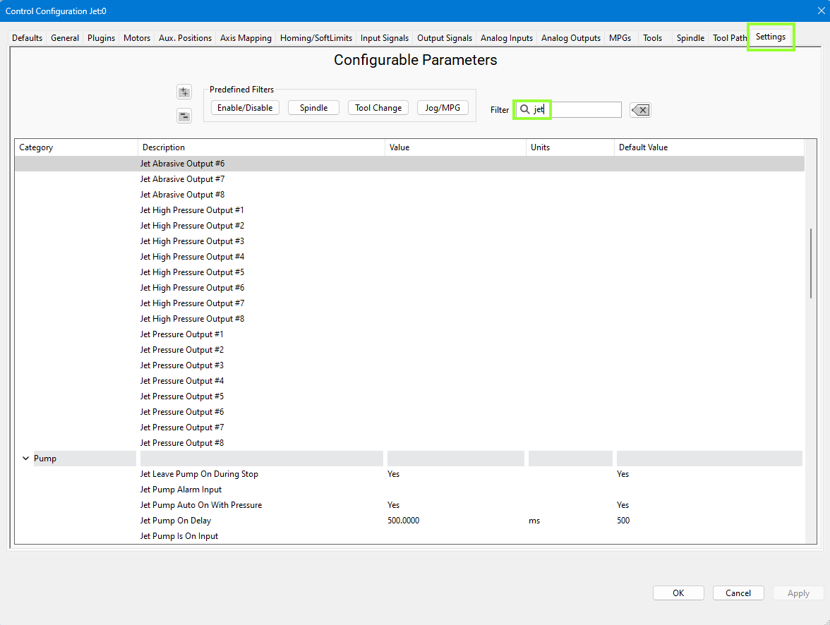
We set the Jet Abrasive Purge Line Delay at 1250 ms which allows the abrasive to stop flowing just before the water turns off. The Jet Off Delay is set to 250 ms which gives us a slight pause after the water turns off and before it starts moving to the next cut. You may adjust these values to appropriate values for you machine.
IO Setup
Virtually every waterjet will need some of following signals. Map each of the ones you need to the correct output. That is done in the Control screen. Configure -> Control - Output Signals. This example is using the simulator. In operation, the device will be the M31, and the Output Names will be EtherCat device names. (1DO.01.0n). Here we have mapped 3 output signals to specific electrical outputs. From this point forward in the configuration, we will use the signals.
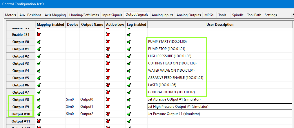
Note that MachPro has a set of pre-defined outputs for your convenience. During configuration of the system, these pre-defined signals need to be mapped to the electrical outputs.
This jet abrasive output is now mapped to a software signal (Output #8). As a software signal, it is now fully accessible to the MachPro software.
| Name | Function | Configuration |
| Jet Abrasive Output(s) | Turns on and off abrasive for the corresponding jet. | Map it to the correct output signal in Mach. |
| Jet High Pressure Output(s) | Turns on and off high pressure for the corresponding jet. Also called things like UHP On/On valve. | Map it to the correct output signal in Mach. |
| Jet Pressure Output(s) | Turns on and off the actual jet. Often called Water On or Jet On. | Map it to the correct output signal in Mach. |
| Jet Pump Output | This turns on the actual intensifier pump. If using a PLC this should trigger the PLC to start the intensifier. Often called Intensifier. | Map it to the correct output signal in Mach. |
For example, Jet Pressure Output #1 here is set to Jet On/Off Solenoid.

A HYDRAULIC OIL OVERTEMP WARNING GMS would be setup as follows:
Some waterjets have a servo controlled Abrasive. For that use these settings:
------------------------ end imported from advanced features material -------------
Pump Not Working
Try running water through the jet. You should be able to get water by doing the following:
- Activate Filter Water Shutoff Valve.
- Activate Boost Pump.
- Activate Jet On.
Cut Recovery
You can configure the axes to move.


{{@2016}}