MachPro Waterjet Operating Manual
![]()
Introduction
Overview
This manual gives an overview for the basic operation of the MachPro Waterjet control. The screens are shown below, followed by a brief summary of the features of each screen. The numbers shown in the screenshot refers to a brief descriptions below the image.
Control Startup
To open the control software, double-click on the profile icon on the desktop.

Languages
| MachPro Version | 2026.5.13.1 and greater |
You may change the display language for the MachPro screen labels and buttons. This is an English-to-target-language word mapping feature, and you may freely switch between available languages. We will add more languages as there is a need. If you see something in your language that would be better translated with a different word or phrase, please submit a ticket so we can update it. support@mach-labs.com
If your CNC experience and training was primarily in English, it may be easier to configure MachPro while it is running in English. When the system is ready for daily operations, switch to an appropriate language for the operators. Be thoughtful in changing the display language. Use it as a tool to simplify your operations.
- From the main MachPro screen, pull down the Operator menu and click Select Language
- You need to restart MachPro after selecting a new language

Control Screen Overview
G-code Tab
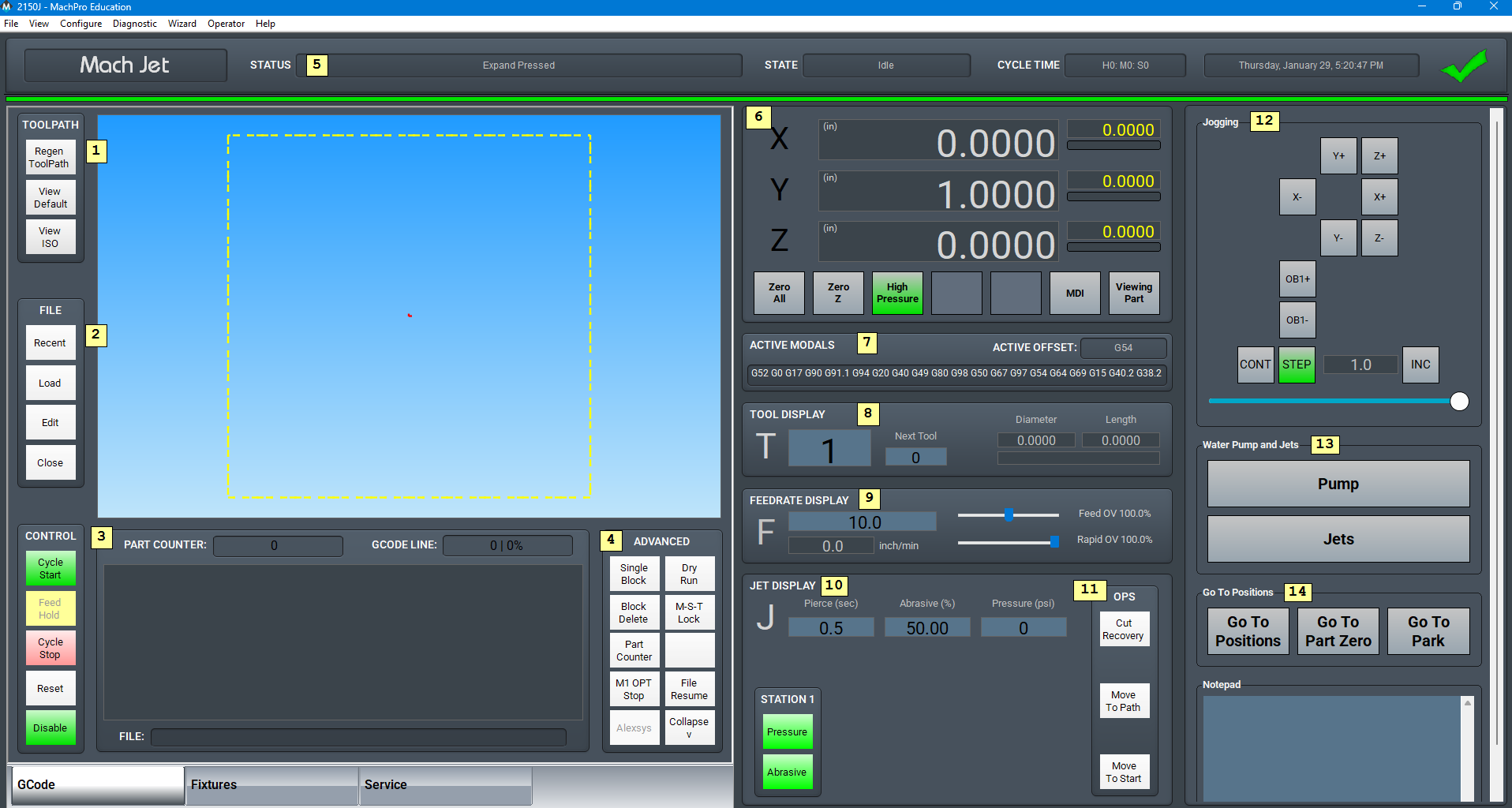
- Toolpath
- Regen Toolpath: refresh the displayed toolpath
- View Top: top view of the part
- View ISO: side view of the part
- File
- Recent: load a recently loaded G-code program
- Load: load a G-code program from the computer
- Edit: edit the G-code program currently loaded into the control
- Close: close the G-code program that is currently loaded into the control
- Control
- Cycle Start - Starts the gcode from from the beginning of the part
- Feed Hold - Pauses the gcode program and keeps the spindle running
- Cycle Stop - Stops the gcode program from running
- Reset - Resets the alarm and also enables the machine
- Disable - Disables the control for software configuration changes
- Advanced
- Single Block: when active, the control will go line by line through the G-code program when the operator presses [Cycle Start]
- Block Delete: when active, the control will skip the lines in the G-code program indicated by their block level
- Part Counter: displays the number of parts that the machine has produced
- M1 OPT Stop: when active, the control will stop at any M1 command in the G-code program and wait for the operator to press [Cycle Start]
- Dry Run: when active, the control will ignore all mist or flood commands
- M-S-T Lock: when active, the control will ignore all M-codes, jet commands, and tool commands
- File Resume: allows the operator to select a line of G-code to start the program from and makes the control ready to run from that location
- Collapse: minimizes the advanced section to only show M1 OPT Stop and File Resume
- Status
- Status: displays the most recent message
- State: displays the current control state
- Cycle Time: displays how long the G-code program has been running
- Date: displays the current date and time of the control
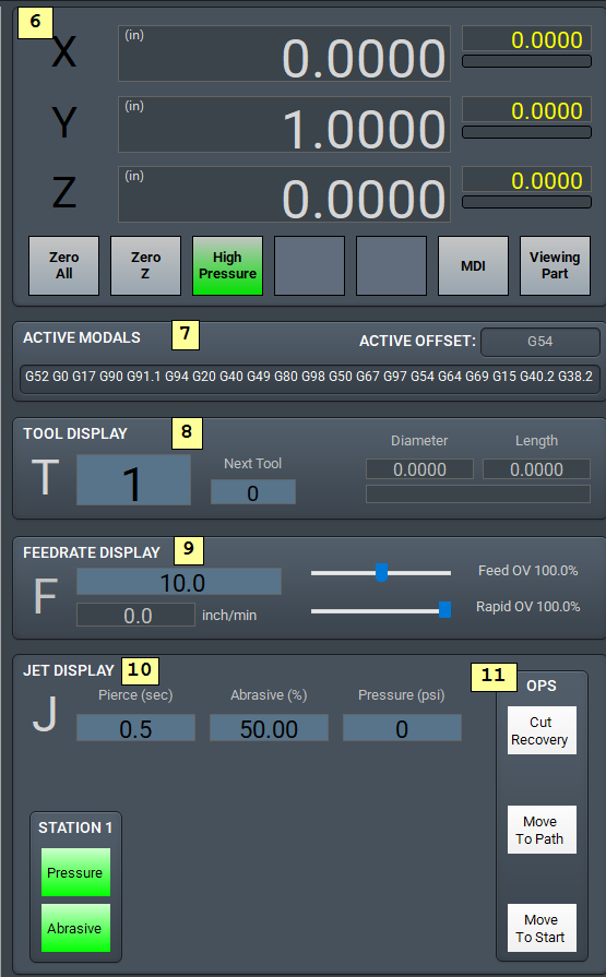
- Axis Digital Readouts

- For each axis on the control, there is the following:
- A DRO displaying the current position
- A DRO displaying the distance left to travel
- A gauge displaying the current load on the axis
- Indication that the axis has not been homed if the axis letter is flashing
- Zero All: Sets the part, or fixture, zero to the current location for all axes
- Zero Z: Sets the Z axis zero
- High Pressure: toggles if the jets operate will in high pressure mode
- MDI: opens or closes a window for G-code commands
- Viewing Part: toggles the axis position DROs between machine coordinates and the current fixture coordinates
- For each axis on the control, there is the following:
- Active Modals
- Active Offset: displays the current fixture offset
- Tool Display
- T: displays the current selected tool number
- Next Tool: displays the next tool to be used by the G-code program
- Diameter: displays the stored diameter of the current tool
- Length: displays the stored length of the current tool
- Feedrate Display
- F: displays the current commanded feedrate
- Feed OV: displays the current feedrate override percentage (0-300%)
- Rapid OV: displays the current rapid override percentage (0-100%)
- Jet Display
- Pierce Delay: displays the current pierce delay while jets are turning on in seconds
- Abrasive Rate: shows the rate of abrasive output at a percentage of ability
- Pressure (PSI)
- Station 1 - 4: toggles which jet stations will turn on when jets are on and which stations also use abrasive
- OPS (See the Cut Recovery documentation)
- Cut Recovery
- Move to Path
- Move to Start
- Jogging
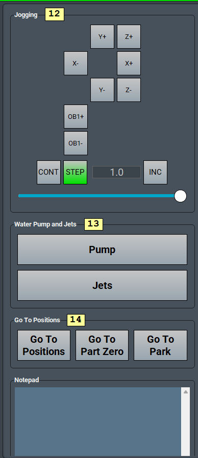
-
For continuous jogging, click the CONT button
-
To use the different jog increments with on-screen jogging:
- Click the STEP button
- Click the INC (increment) button to select the jog distance to use per axis click
- The INC button will cycle through all five of the increment values
- Click the appropriate axes buttons to jog your system
-
- Water Pump and Jets
- These provide manual control of the pump and jets, but they are normally managed by the G-Code
- Go To Positions
- See the documentation for MachPro Modify GoTo Positions

The right panel is part of the dashboard feature which you may customize to suit your operating needs. MachPro Widgets, Dashboard, Commands, and Function Buttons
Fixtures Tab
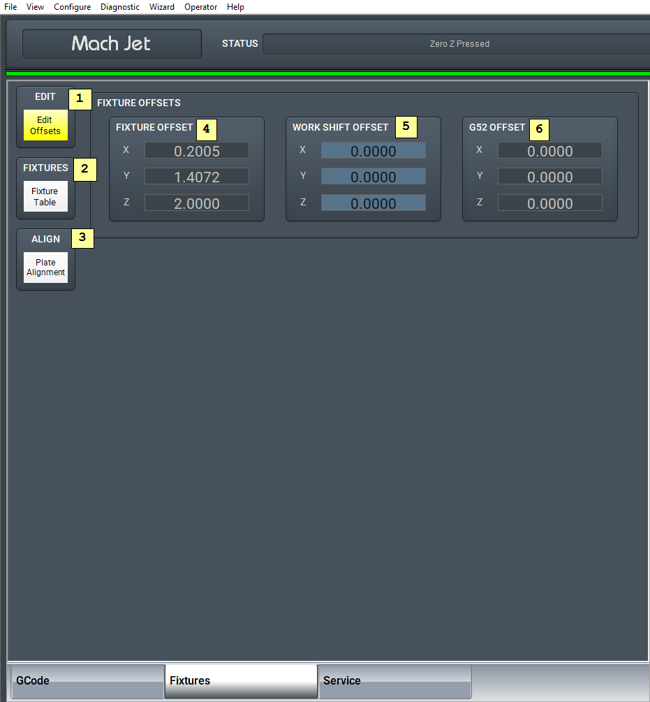
- Edit
- Edit Offsets: edit the active fixture offsets
- Fixtures
- Fixture Table: view and edit the fixture table for all fixtures
- Align
- Plate Alignment: open plate alignment wizard to rotate the toolpath when the work piece is not square on the table.
- Fixture Offset
- Displays the current fixture offset for each axis
- Work Shift Offset
- Displays the current work shift offset for each axis and allows the operator to edit them
- G52 Offset
- Displays the current G52 offset for each axis
Service Tab
Maintenance Tab
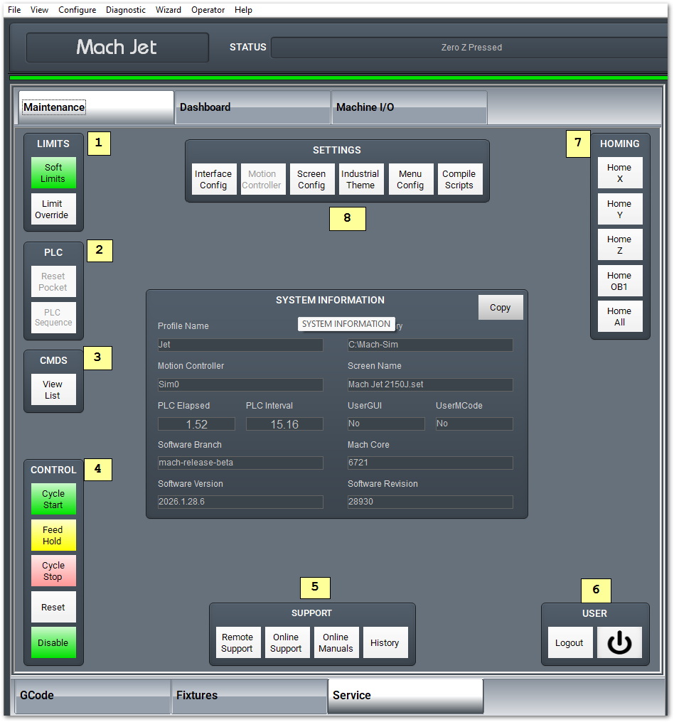
- Limits
- Soft Limits: toggles software limits on or off
- Limit Override: toggles to allow for the machine to move off a limit switch
- PLC
- Reset Pocket: only used for tool changers
- PLC Sequence
- Commands (CMDS)
- This is a tool to run special commands. Contact support for assistance.

- This is a tool to run special commands. Contact support for assistance.
- Control
- Cycle Start - Starts the gcode from from the beginning of the part
- Feed Hold - Pauses the gcode program and keeps the spindle running
- Cycle Stop - Stops the gcode program from running
- Reset - Resets the alarm and also enables the machine
- Disable - Disables the control for software configuration changes
- Support
- Remote Support: starts a TeamViewer session
- Online Support: opens the online support page
- Online Manuals: opens the MachGroup bookstack site
- History: view the operator message history
- User
- Logout: logs out of the Windows username
- Power: turns off the computer
- Homing
- Home X: sends X axis to do its homing routine
- Home Y: sends Y axis to do its homing routine
- Home Z: sends Z axis to do its homing routine
- Home All: all axes do their homing routine in their configured order
- Settings
- Interface Config: opens the MachPro interface settings for editing
- Motion Controller: opens the configuration for the active motion controller
- Screen Config: opens the configuration to change the colors and password protect aspects of the screen
- Industrial Theme: applies standard colors to screen objects
- Toggle Menu: opens settings for top menu bar
- Compile Scripts: refreshes programming scripts

Dashboard Tab
The dashboard is used to make the control just the way you want it! For more information, read here.
Machine I/O Tab
This tab is used for diagnostics and shows all enabled machine signals.
Homing
To home the machine, begin by pressing the [Reset] button. Then navigate to the [Service/Maintenance] tab and press [Home All]. There is an optional parameter to prompt the user to home the machine on startup.
Programmed Movement
MDI
To command a movement using the MDI feature, press the [MDI] button.


G-code
The primary method of commanding motion is using G-code files. G-code files can be hand written, generated by a wizard, or generated from CAD files using a CAM program.
Toolpath Screen
The controls to manipulate the toolpath screen are as follows:
-
- Zoom – Right click with the mouse and move mouse up/down or using the scroll wheel on the mouse
- Rotate – Left click with the mouse and rotate the part by moving the mouse
- Pan – Press and hold [Ctrl] on the keyboard and left click with the mouse, then pan by moving the mouse (one-hand control option is to use left and right mouse click and move the mouse. No [Ctrl] press needed)
Cut Recovery
The control comes with a feature that allows the user to jog the machine to anywhere on the part and start running the G-code program from there. Operation of this feature is as follows:
- Jog the machine close to the position to start from. Using the toolpath on the screen may help the operator get close to the path.
- Press [Cut Recovery] in the Jet Display group. The operator will be asked to press [Cycle Start] to confirm the motion on to the path.
- The control will evaluate if the jets should be on at this point in the file, and then ask the operator to press [Cycle Start] to confirm running the file from this point.
Jet Control
G-code Jet Commands
The jet is controlled with with M-codes M3 (On) and M5 (Off). These commands can be done in G-code or through MDI. Pierce, abrasive and High Pressure timers can all be set manually or set while calling the M3. Values set with M3 will override values set manually. The command should look like this: M3 P H E
P is pierce delay, H is pressure delay and E is abrasive delay. Time will be set in seconds. Example: M3 P2 H3 will turn on the jet with a 2 second delay and pressure on for 3 seconds. E is not called in this example so it will default to the user settings instead of what is called in the G-Code.
M-Codes
|
M3 |
Jets On, Optional values: P = Pierce Delay (sec) E = Abrasive Delay (sec) H = Pressure Delay (sec) K = Abrasive Rate (0-100%) S = Pressure (psi) overwrites #9000 |
| M5 | Jets Off |
| M170 | Jets Abrasive Master Enable On |
| M171 | Jets Abrasive Master Enable Off |
| M172 | Jets High Pressure On |
| M173 | Jets High Pressure Off |
G-Code Parameters
|
1910 |
Wiggle Piercing Circles During Pierce Delay (1 = On, 0 = Off) |
| 1911 | Wiggle Piercing Number of Loops |
| 1912 | Wiggle Piercing Diameter |
| 1913 | Wiggle Piercing Feedrate |
Pound Variables
|
9000 |
Commanded Jet Pressure (psi) |
Manual Jet Control
To control the jet separately from G-code, use the spindle controls on the operator panel. The buttons for [FWD] and [REV] will both turn the jet on, while the [STOP] button will turn the jet off.
Jet Run Settings
The control supports up to four jets. A jet must be enabled in the parameters by mapping the appropriate outputs to control the pressure on, high pressure, and abrasive.
When commanding the jets on, the selection of which jets turn on is done on the screen. Each station can be selected individually if it should turn on and if it should use abrasive. All stations that are on will operate in high-pressure mode or not together. All stations using abrasive will use abrasive at the same rate. All stations that turn on will use the same pressure, abrasive, and pierce delays.

Configuring Jet Parameters
The MachPro settings can be accessed by pulling down Configure -> Control -> Settings tab Full documentation is in the setup manual: Setup the first jet
In the [Jet/General] section, are parameters for the number of jets and the delay times to use while turning the jets on. The control supports up to four jet stations that are controlled simultaneously. The selection of which jets turn on is done on the screen.
For each jet, outputs must be mapped for turning on their pressure, abrasive, and high pressure states in the [Jet/Output] section. If the abrasive is a servo motor feed system, then the servo motor needs to be enabled in the [Jet/Abrasive] section and the appropriate axis ID assigned to it. The axis ID is the axis number that the motor is mapped to in MachPro config. The axis must be an OB axis (axes 6-11).
To allow for jet height control while the machine is cutting, an axis must be mapped to the Z override axis. This axis ID must be an OB axis (axes 6-11) and must not be the same as an abrasive motor. The control must be restarted for changes to this value to take effect.
Jet On and Off Sequence
All enabled jets will turn on or off the outputs at the same time.
Jets On Diagram (M3)

Jets Off Diagram (M5)

Operating the Intensifier
Startup Sequence
When the jet pump is commanded on (M174), the control will automatically execute the following sequence:
Pump Status: STARTING
- Bleed Down Valve - CLOSES
- The bleed-down valve closes to prepare the system for pressurization
- Inlet Water Valve - OPENS
- Inlet water valve opens to supply water to the intensifier
Pump Status: INLET WATER ON
- Boost Pump - STARTS
- Boost pump motor starts to pre-pressurize the water supply
- Water Cooling - STARTS
- Water cooling system activates to maintain proper operating temperature
- Inlet Water Pressure Check
- If pressure sensor is mapped: Waits for inlet water pressure good signal (timeout per configured parameter)
- If pressure sensor is not mapped: Delays for configured time to allow pressure to stabilize
- If pressure is not detected within timeout period, triggers "Intensifier Inlet Water Low Pressure Alarm" and machine disables
Pump Status: STARTING MOTOR
- Pump Motor Output - ACTIVATES
- Main pump motor output is turned on
- Momentary On Output - PULSES (if mapped)
- If configured, sends a momentary pulse to start the pump motor (350ms pulse)
- Pump On Delay
- Waits for configured pump delay time to allow motor to reach operating speed
- Displays progress bar: "Waiting for Jet Pump Delay"
- Pump Is On Input Check (if mapped)
- Waits for confirmation signal that pump motor is running
- Timeout: 60 seconds
- Displays: "Waiting for Jet Pump to turn On"
Pump Status: MOTOR UP TO SPEED
- Pressure Ramp Delay
- Waits for configured ramp delay time as pressure builds
- Displays progress bar: "Waiting for Pressure Ramp Up Time"
Pump Status: PRESSURE RAMPING DONE
- Safety Monitoring Active
- All temperature, pressure, and stroke monitoring systems are now active
- Ready for cutting operations
Shutdown Sequence
When the jet pump is commanded off (M175), the control will automatically execute the following sequence:
- Pump Motor Output - DEACTIVATES
- Main pump motor output is turned off
- Momentary Off Output - PULSES (if mapped)
- If configured, sends a momentary pulse to stop the pump motor (350ms pulse)
- Bleed Down Valve - OPENS
- Bleed-down valve opens to safely depressurize the system
- Boost Pump - STOPS
- Boost pump motor is turned off
- Inlet Water Valve - CLOSES
- Inlet water valve closes to stop water supply
Pump Status: OFF
- Water Cooling - CONTINUES RUNNING
- Water cooling system remains active for the configured cool-down period
- Default: 60 seconds after pump shutdown
- This ensures the intensifier cools down properly before cooling water stops
- Water Cooling - STOPS (after delay)
- After the configured delay period elapses, cooling water is turned off
- Cool-down timer is managed automatically by the control
Troubleshooting Intensifier Alarms
| Alarm/Warning | Possible Causes | Corrective Action |
| Check Valve Temperature Alarm | Inadequate cooling, excessive duty cycle, failing check valve | Check cooling flow, reduce duty cycle, inspect check valve |
| Oil Temperature Warning/Alarm | Low oil level, insufficient cooling, excessive ambient temperature | Check oil level, verify cooling system operation, improve ventilation |
| Oil Low Alarm | Oil leak, insufficient initial fill | Inspect for leaks, refill to proper level |
| Inlet Water Pressure Warning/Alarm | Low supply pressure, clogged filter, failing pressure sensor | Check supply pressure, replace filters, test sensor |
| Bleed Down Over Temperature | Excessive bleed-down frequency, valve malfunction | Allow cool-down time between cycles, inspect valve operation |
| Stroke Over Speed Alarm | Pressure control malfunction, improper parameter settings | Check pressure regulation system, verify stroke speed settings |
| Stroke Stall Alarm | Mechanical binding, insufficient inlet pressure, low oil level | Inspect for obstructions, check water supply and boost pump, check oil level |
Notes
- All monitoring systems only activate when the pump status indicates the pump is running (MOTOR UP TO SPEED or PRESSURE RAMPING DONE)
- The water cooling delay timer begins when the pump status changes to OFF
- Debounce times help prevent nuisance alarms from momentary sensor fluctuations
- Always verify all safety sensors are functioning properly before starting operations
- Review alarm history in Global Monitoring System diagnostics for troubleshooting patterns
Operating Pressure Control
Setting Commanded Pressure
The operator can set the commanded cutting pressure in several ways:
- Manually adjust the pressure value on the control screen before starting a cut
- In G-code using M3 command: M3 S[pressure] - Example: M3 S50000 sets pressure to 50,000 psi
- In G-code by setting pound variable: #9000 = [pressure]
The commanded pressure is stored in pound variable #9000 and can be viewed or modified at any time.
Pressure Control Operation
When the pump starts (M174):
- System reads commanded pressure from #9000
- Pressure output begins at minimum value
- Output smoothly ramps to commanded pressure over configured ramp-up time
- If closed-loop is enabled:
- PI controller activates once motor is up to speed
- System continuously measures actual pressure
- Output automatically adjusts to maintain commanded pressure
- If open-loop:
- Output holds at commanded value (no automatic adjustment)
During operation:
- Operator can change commanded pressure at any time
- System smoothly ramps to new pressure value
- Closed-loop mode maintains pressure even if conditions change
When the pump stops (M175):
- Output smoothly ramps down to minimum value over configured ramp-down time
- PI controller is reset to prepare for next cycle
- Output returns to minimum (zero pressure)
| http://www.mach-labs.com | MachLabs Documentation | support@mach-labs.com |
The MachLabs Team
14518 County Road 7240, Newburg, MO 65550
support@mach-labs.com