MachPro Mill and Router Setup Manual
{{@2007#bkmrk--1}}
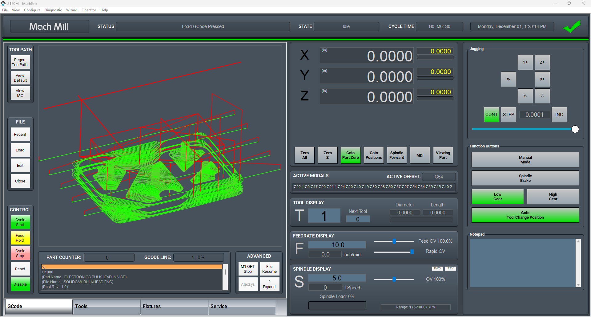
MachPro 26 CNC Software Roadmap
Introduction
Some of the following configuration steps are integrated with the MachPro software. The M31 Motion Control Setup Manual includes the information you need for the M31. Compatible motion controllers should complete the MachPro Compatible Motion Controller Configuration Settings
Please refer to the Motion Controllers documentation and the appropriate MachPro Motion Controller Integration Documentation for the following steps:
- Use a shielded network cable to connect the motion controller and the MachPro computer
- Connect the cables between the motion controller and the drives
- MachPro Startup and license install
- Axis setup
- Axis calibration
- Mapping input signals (see default mapped inputs and outputs table below)
- Homing setup
- Homing slave axis - if present
- Troubleshooting
- Soft Limits setup
- Mapping output signals
- Using outputs
- Spindle Setup
Languages
{{@2205}}
Default Mill and Router I/O mappings
Default inputs
The first row in both the inputs and outputs lists the M31 as the device. Your motion controller should be in the drop-down list under Device.
| SignalID | SignalName | Enabled | Device | Name | ActiveLow | Description |
| 1 | Input #0 | 1 | M31 | 1DI.01.00 | 0 | GENERAL INPUT 0 (1DI.01.00) |
| 2 | Input #1 | 1 | 1DI.01.01 | 0 | GENERAL INPUT 1 (1DI.01.01) | |
| 3 | Input #2 | 1 | 1DI.01.02 | 0 | GENERAL INPUT 2 (1DI.01.02) | |
| 4 | Input #3 | 1 | 1DI.01.03 | 0 | GENERAL INPUT 3 (1DI.01.03) | |
| 5 | Input #4 | 1 | 1DI.01.04 | 0 | COOLANT LOW (1DI.01.04) | |
| 6 | Input #5 | 1 | 1DI.01.05 | 0 | DOOR OPENED (1DI.01.05) | |
| 7 | Input #6 | 1 | 0 | GEAR SELECT (DI.6) | ||
| 8 | Input #7 | 1 | 0 | UNUSED INPUT (DI.7) | ||
| 9 | Input #8 | 1 | 0 | PROBE (DI.8) | ||
| 10 | Input #9 | 1 | 0 | SETTER PROBE (DI.9) | ||
| 11 | Input #10 | 1 | 0 | SETTER LIMIT (DI.10) | ||
| 12 | Input #11 | 1 | 0 | LUBE LOW (DI.11) | ||
| 13 | Input #12 | 1 | 0 | GEN 1 X16 (DI.12) | ||
| 14 | Input #13 | 1 | 0 | GEN 2 X17 (DI.13) | ||
| 15 | Input #14 | 1 | 0 | GEN 3 X18 (DI.14) | ||
| 16 | Input #15 | 1 | 0 | UNUSED INPUT (DI.15) | ||
| 65 | Motor 0 Home | 1 | 1DI.01.09 | 0 | X HOME (1DI.01.09) | |
| 66 | Motor 1 Home | 1 | 1DI.01.11 | 0 | Y HOME (1DI.01.11) | |
| 67 | Motor 2 Home | 1 | 1DI.01.12 | 0 | Z HOME (1DI.01.12) | |
| 97 | Motor 0 ++ | 1 | 1DI.01.08 | 0 | X LIMIT ++ (1DI.01.08) | |
| 98 | Motor 1 ++ | 1 | 1DI.01.10 | 0 | Y LIMIT ++ (1DI.01.10) | |
| 99 | Motor 2 ++ | 1 | 1DI.01.12 | 0 | Z LIMIT ++ (1DI.01.12) | |
| 129 | Motor 0 -- | 1 | 1DI.01.09 | 0 | X LIMIT -- (1DI.01.09) | |
| 130 | Motor 1 -- | 1 | 1DI.01.11 | 0 | Y LIMIT -- (1DI.01.11) | |
| 131 | Motor 2 -- | 1 | 1DI.01.13 | 0 | Z LIMIT -- (1DI.01.13) | |
| 161 | Probe | 1 | 1DI.01.14 | 0 | PROBE (1DI.01.14) | |
| 164 | E-Stop | 1 | 1DI.ESTP | 0 | ESTOP (1DI.ESTP) | |
| 183 | Probe1 | 1 | 1DI.01.15 | 0 | TOOL SETTER INPUT (1DI.01.15) | |
| 251 | Input #100 | 1 | 1DI.ALRM | 0 | DRIVE FAULT (1DI.ALRM) |
Default outputs
| SignalID | SignalName | Enabled | Device | Name | ActiveLow | Description |
| 1050 | Output #0 | 1 | M31 | 0 | LUBE PUMP (DO.0) | |
| 1051 | Output #1 | 1 | 1DO.01.01 | 0 | GENERAL OUTPUT 1 (1DO.01.01) | |
| 1052 | Output #2 | 1 | 1DO.01.02 | 0 | GEAR RANGE 1 (1DO.01.02) | |
| 1053 | Output #3 | 1 | 0 | SPINDLE BRAKE (DO.3) | ||
| 1054 | Output #4 | 1 | 0 | GEAR RANGE INCREASE (DO.4) | ||
| 1055 | Output #5 | 1 | 0 | GEAR RANGE DECREASE (DO.5) | ||
| 1056 | Output #6 | 1 | 0 | GENERAL ONE (DO.6) | ||
| 1057 | Output #7 | 1 | 0 | GENERAL TWO (DO.7) | ||
| 1142 | Spindle Fwd | 1 | 1DO.FE | 0 | (SPINDLE FORWARD) 1DO.FE | |
| 1143 | Spindle Rev | 1 | 1DO.RE | 0 | (SPINDLE REVERSE) 1DO.RE | |
| 1144 | Coolant On | 1 | 0 | FLOOD COOLANT (DO.2) | ||
| 1145 | Mist On | 1 | 0 | MIST COOLANT (DO.1) |
Spindle Calibration
This is primarily for mills where the speeds and feeds are precise, and directly affect the finish and accuracy of the final part. Spindle speeds on routers are usually not as precise.
Spindle Settings
{{@2047}}
Global Monitoring System (GMS)
{{@2002}}
Lube System Setup
{{@2046}}
Modifying GoTo Positions
{{@2045}}
Tool Setters and Offsets
{{@1995}}
Probing Wizard
{{@2206}}
Blum Probing Modules
{{@2203}}
Tool Changers
{{@1999}}
{{@1998}}
Drill Bank Setup and Operation
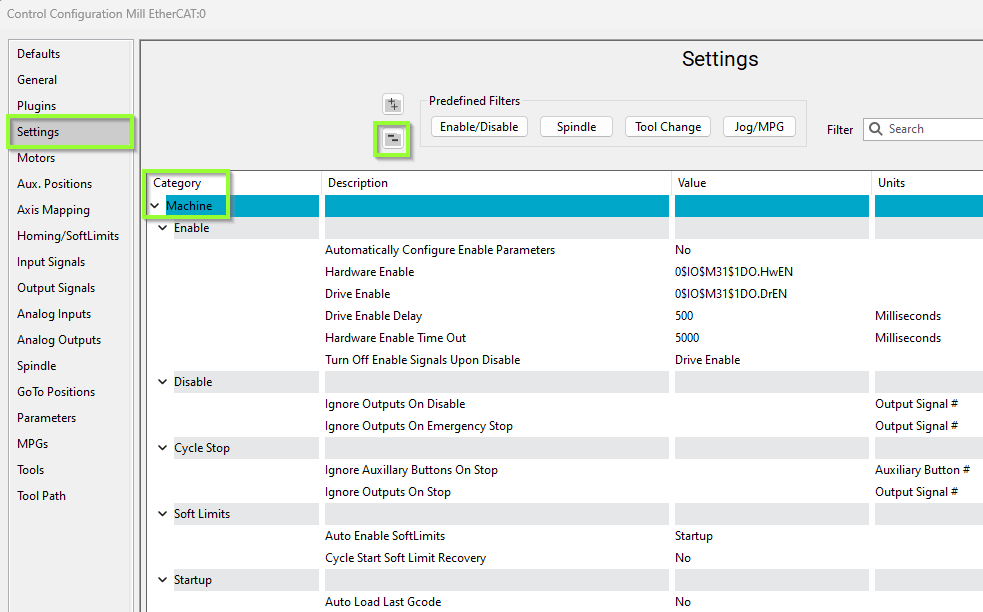
Other Machine Settings
Pull down Configure -> Control and select the Settings Tab and scroll down to the Machine section
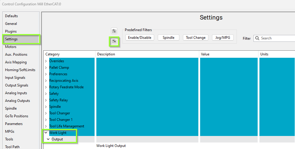
Work Light Output
Pull down Configure -> Control and select the Settings Tab and scroll down to the Work Light section
Additional Information
For information about MachPro Software Operation please see the MachPro Mill/Router Operating Manual
{{@2016}}