MachPro Mill and Router Setup Manual
{{@2007#bkmrk--1}}
Configure Software
There are two options for setting up units and soft limits. Typically, the easiest way is to use the MachPro Knee Mill Setup Wizard. For more complex configurations, or customization, please refer to the M31 Motion Control Setup Manual
Knee Mill Setup Wizard
Select the Kneemill Setup Wizard from the Configure drop down on the main menu. This will guide you through an initial setup process that will allow you to set axis unit calibration, soft limits, and spindle calibration. You can also go through each step manually by following the information on completing the set up process for Units Calibration and Soft Limits outlined below.

Upon selecting the Kneemill Setup Wizard, you will be presented with a selection of configuration options. Yellow triangles indicate which features have not been completed yet, and green check marks correspond to previously completed items. It is suggested to do the items in the following order:
- Units
- Softlimits
- Spindle Calibration
- Backlash

Units Calibration
To set the units for each axis, the pitch of the ballscrew, the number of teeth on the ballscrew pulley, and the number of teeth on the motor pulley must be known. An advanced option is available for other systems of motion or if the data is not known.
The wizard will go through each axis individually in order (X, Y, Z). For each axis, you must enter the three pieces of data. Every time you change the data, the new units will be calculated and applied to the axis. To verify the units, a 1" dial indicator can be used. The wizard supplies options to move the axis back and forth distances up to an inch. Otherwise, verification can be done by manually jogging or commanding MDI motion.

Soft limits
It is suggested to go through this part with the machine disabled and to use the handwheels to move the machine. It is possible to move the machine with the jog functionality or pendant if the speed is turned down and caution is used.
Use extreme caution when jogging the machine. Until the soft limits are set it is possible to run an axis to its hard limit.
The softlimits wizard will go through the three axes in order (X, Y, Z) and ask you to move the machine first to maximum travel and then to minimum travel. The positions should be within machine physical limits and within any limit switches on the machine, but should encompass most of the usable machine.

For each position, you will either need to select Set Softlimit or Skip in order to proceed. As you move through the wizard, the image will change to help you visualize the correct positions. When you set the maximum softlimits for each machine, the control will set your Home position to the same place, unless the machine has previously been homed.
For reference, while facing the machine, X maximum travel is with the table all the way to the left and the spindle nose all the way to the right of the table. Y maximum travel is with the table as close to the operator as it can go and the spindle nose near the far edge of the table.
After exiting the wizard, limits will be activated. It is now possible to enable the machine and jog the axes into their limits. When the limit is reached, the machine will cease moving in that direction. It is a good idea to turn down the jog rate and test the limits at this point.
Use extreme caution while testing limits in the event that an axis was accidentally skipped or set at an incorrect position.
Backlash
Backlash is caused by the gaps between moving parts such as gears and ballscrews. It is the amount of movement one component can make in one direction without causing motion in the next connected part. Most mechanical systems have some backlash - even when new. If the mechanics are too tight, binding and excessive wear will result. As the gears and ballscrews wear, the backlash will increase, and accuracy will decrease. Ongoing testing and maintenance of your mechanical system is required to minimize backlash.
The M31 provides software backlash compensation as a short-term solution for small, stable amounts of backlash. To calculate the backlash of an axis use How To Test For Backlash
In the case that you have less then .0005" of backlash, this step may be skipped. Backlash compensation will not completely compensate for all mechanical deficiencies.
Be sure to start this wizard with each axis near the middle of travel. The machine needs minimum of 1" of travel in all directions for this wizard to succeed.
The wizard supplies buttons for moving the machine positive and negative 1 inch, input for the amount of error, and an indication of direction of error.

For each axis, move the axis negative and then attach a dial indicator and zero it. Then move the axis positive once. Input the error from the indicator and select the direction of error. Then select Calculate & Apply. Verify the backlash by repeating the process until the machine is consistent.
VFD Setup
Your Variable Frequency Drive will need to be configured for your spindle motor. Please refer to the manufacture's documentation for both the VFD and spindle motor. The VFD will have a way to view and change parameters through the face of the drive, and there may also be software that you can run and connect to the VFD through a USB cable.
You can find out what parameters need to be changed by looking at the info on your spindle motor name plate. Check and change any of the values that need it (Number of poles, wattage, amperage, etc.) to make sure your spindle runs at peak performance.

Spindle Calibration
The spindle calibration wizard requires you to read the specifications from the spindle and insert them into the wizard. The information needed is the maximum RPM for low gear, the maximum RPM for high gear, and the amps for full load. These should be input and then Save selected.
The spindle can be tested by inputting a spindle speed on the screen and then pressing the Spindle FWD or Spindle REV buttons on the panel. If the spindle is turning the incorrect direction, the Reverse spindle direction check in the wizard can be toggled. Be sure to select Save.

If you want to calibrate your spindle with a tachometer, please see the VFD - Spindle Calibration documentation.
{{@1996}}
Manual Setup
Units Calibration
Before the machine is homed or any further setup is completed we must calculate our steps per/unit and calibrate the motors accordingly. There is both an automatic process and a manual process: 2.4 Axis Calibration
Homing
With the motor units calibrated, we can now set the machine zero and set up the software limits.
Machine zero is used by the control for all movement calculations, but you will not typically use it directly. Your RPKM system has absolute encoders that maintain the position of each axis even when the machine is powered down. We will set the machine zero here once and you will not need to home your mill when you start it up.

- Go to your service tab. Turn off soft limits, enable and ensure that your axis labels are flashing red and yellow. If not, please contact MachLabs for assistance de-referencing your axes.

- Carefully jog X to the most negative location that you want to use (the soft limit location), and then jog positive approximately one inch, where the X machine zero will be set.
- Repeat that process for the Y axis.
- Carefully jog Z up to the most highest location that you want to use (the soft limit location), and then jog down approximately one inch, where the Z machine zero will be set.
- Navigate to the Service Tab and click Home All. This sets the machine zero for all axes. If the Home All button is not active, please contact MachLabs and we will help you de-reference all axes so that you can set your machine zero.

Soft Limits
Next we need to set up the soft limits to prevent crashes. On the upper left hand side of the screen pull down Configure and then Config Soft Limits.
Follow the prompts listed. Soft limit set up can be done on all axes at the same time, or one axis at a time. Continue until all axes are complete. Carefully test each axis to make sure that it will not go past the position you set for its soft limit.
Backlash
Backlash is caused by the gaps between moving parts such as gears and ballscrews. It is the amount of movement one component can make in one direction without causing motion in the next connected part. Most mechanical systems have some backlash - even when new. If the mechanics are too tight, binding will cause excessive wear. As the gears and ballscrews wear normally, the backlash will increase, and accuracy will decrease. Ongoing testing and maintenance of your mechanical system is required to minimize backlash.
The M31 provides software backlash compensation as a short-term solution for small, stable amounts of backlash. To calculate the backlash of an axis use How To Test For Backlash.
To manually adjust the software compensation for backlash, use these instructions: Backlash Repair and Compensation. Backlash compensation can not completely compensate for all mechanical backlash.
In the case that you have less then .0005" of backlash, this step may be skipped.
Lubrication Pump
Your kit is pre-configured with a relay to control the Lube Pump, as seen above. You can change the frequency and duration for the pump in the MachPro settings.
Pull down Configure -> Control and select the Settings Tab
Search for "Lube"
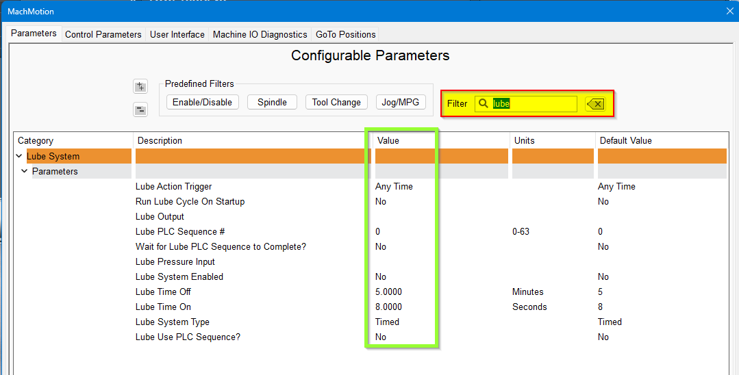
Adjust the values according to your machine's needs. Note that lube pumps vary widely in their output. Start conservatively and increase the values to achieve proper lubrication.
Additional Information
For information about MachPro Software Operation please see MachPro Mill/Router Operating Manual
{{@2016}}