PRIVATE MachPro Configuration
MachPro is used for multiple machine types. Some of this documentation will be useful for all machine types, and some is only for certain machine types. Much of the software is already configured with values that that work well for most people. There are some portions of the software that will be most useful if you have additional details.
Tool Table Offsets
Open the Tool Table

Open the Tool Table Editor
-
In the tool table window, click Edit → Table Fields.

Add the X and Y Offset Fields
-
Click the Optional Field tab.
-
Find the field name XOffset, select it, and click Move Pri.
-
Do the same for YOffset.
-
Click OK to save.
-
You should now see X and Y offset columns in your tool table.
Set the Master Tool
-
Choose one tool to be your master tool.
Measure and Enter Offsets
- For each other tool, measure the distance from the master tool in both X and Y directions.
-
Enter those distances into the XOffset and YOffset fields for each tool.
Tool Spindle Rotation Options
Open the Tool Table
-
Click View → Tool Tables.
Open the Tool Table Editor
-
Click Edit → Table Fields.

Add a User Field for Spindle Options
-
Click the User Field tab.
-
Click Add.
-
Set up the new field exactly as shown in the example image.
-
Click OK when done.

View and Use the User Field
-
Click View → User Fields.
-
The new user field will now appear for each tool.

Set Rotation for Each Tool
-
For every tool, choose the correct spindle rotation option.
-
Example: For a probe tool, select No Rotation.
-
When you select a tool with “No Rotation,” you cannot turn on the spindle.
-
If you try, you will see an alarm message instead.


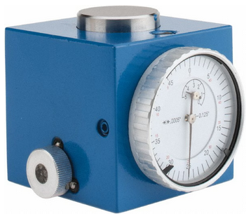
Tool Setters and Offsets
![]()
Open the Calibrate Tool Setters window. Found on the Tools tab.

Creating a Manual Tool Setter
Mapping the input to a software signal
Pull down Configure -> Control and select the Input Signals tab.
Some signals are pre-configured when MachPro is installed.
Tool Setter Limit (Over Travel) maybe be mapped to Input #6
Tool Setter Input may be mapped to Probe1.
 |
 |
 |

GoTo Position
- If the tool setter is permanently mounted, then define a GoTo Position so the spindle can safely move to the tool setter before touch-off.
- This ensures a consistent and safe approach, reducing the risk of collisions.
1. Add or Edit a tool setter
- In the Tool Setter tab, click Add New to create a new tool setter.
- Enter a unique name for the tool setter.
- Select the new tool setter from the list to display its settings on the right side.
2. Setter Type
- Under Setter Type, select Manual.
3. Tool Setter Height
- This is used with randomly placed tool setters to determine the Z fixture offset. If you have a fixed position tool setter, leave this value at 0.0
- Measure the physical height of the tool setter.
- Enter the measured value in the Tool Setter Height field.
4. Z Position
-
For a fixed positionsetter:
- Use the Z Position Wizard to determine the machine coordinate for the top surface of the setter.
- Once set correctly, this value should not be changed.
-
If the setter is mounted outside the soft limits, enable Disable Softlimits.
-
Once the Z position and height are calibrated, the system will automatically use these values for all tool length offset calculations.
Randomly placed tool setter
-
Set Initial Parameters
- Set the Z Position to 0.0.
- Leave all GoTo fields blank.
- This indicates that the setter position may change between uses.
-
Prepare the Spindle
- Remove all tools from the spindle.
- If the spindle uses tool holders or collets, insert an empty holder while setting the Z position.
-
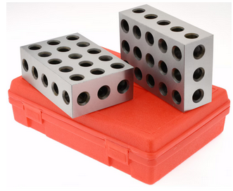
Position the Tool Setter
- Place the manual tool setter or gauge blocks on the table at the desired location.
-
Set the Z Position
- Carefully jog the spindle down until the tool tip touches the surface of the setter.
- Click Set Position.
- This records the Z position using the current spindle location and the entered Tool Setter Height value.
-
Measure Tools
- Insert each tool required for the job.
- Perform a tool measurement cycle for each tool to record its length offset.

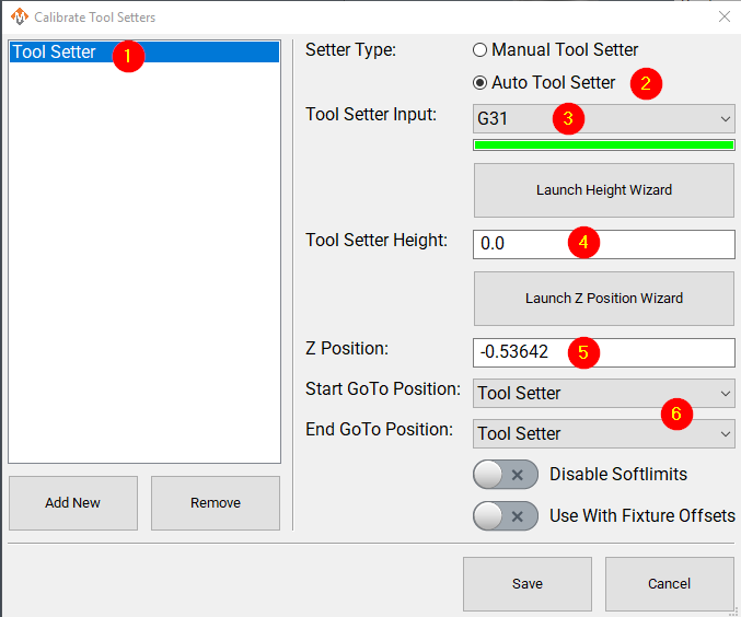
Creating an Auto Tool Setter
Click on the Tools tab at the bottom of the MachPro screen, then on the Tool Setters button in the middle of the left side of the screen.
If you are setting up a RapidChangeATC changer and setter, also refer to RapidChangeATB Tool Changer and Tool Setter
 |
 |
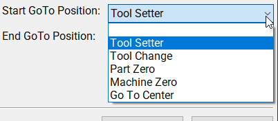 |
-
Define GoTo Positions for the tool setter.
-
- Selecting a GoTo position allows the spindle to move automatically to the setter before touching off.
- This is recommended for permanently mounted setters.
- If the setter is located outside the soft limits, enable Disable Softlimits.
- Selecting a GoTo position allows the spindle to move automatically to the setter before touching off.
-
-
Click Add New to create a new tool setter.
- Enter an appropriate name for the tool setter.
-
Set the Setter Type to Auto.
-
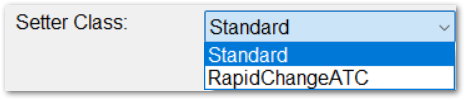
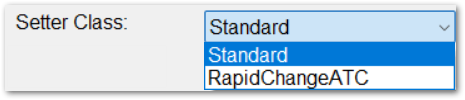
Leave the Setter Class as Standard unless you are configuring a RapidChangeATC tool setter for stand-alone use.
-
Select the Probe Input that the tool setter is wired to. The 4 input signals available are:
- Probe (G31)
- Probe1 (G31.1)
- Probe2 (G31.2)
- Probe3 (G31.3)
-
If the correct input probe signal has been selected, then indicator bar below the input selector will turn green when the tool setter is triggered. Manually trigger the setter (or have a helper do so) to confirm the correct input is selected.
-
If the tool setter height is known, enter the value in the Tool Setter Height field.
- If the height is unknown, click Launch Height Wizard and follow the on-screen instructions to measure it.
- The tool setter must be wired to the control for this process.
-
Set the Z Position to the machine coordinate of the surface where the tool setter rests.
- If the position is unknown, use the Z Position Wizard to determine it.
- For a randomly placed setter, set the Z Position to 0.0. This value will be defined each time before measuring tools.
- See also: Using a Randomly Placed Tool Setter.
-
For randomly placed setters, leave all GoTo Position fields blank.
- Manually jog the spindle to the setter or place the setter beneath the spindle as needed.
- The machine will not perform automatic jogging during this process.
Align Tool Edge to Center of Tool Setter This feature positions the edge of the tool precisely at the center of the tool setter, ensuring accurate alignment and consistent measurement results. Pull down Configure -> Control and select the Settings Tab. Scroll down to the Measurements and Offsets section.

-
Set Tool Setter Align Tool Edge To Setter to Yes.
-
Configure the Tool Setter Align Tool Edge Offset parameter.
- Choose between Tool Radius or Tool Setter Offset as the source for the offset used to align the tool edge to the center of the setter.
-
Select whether to Align (X or Y) Axis to Setter to define which way the tool moves when aligning the edge to the center of the setter.
-
Close the Settings menu
-
If you selected Tool Setter Offset, then open the Tool Table and click the Edit option
-
Select the User Fields tab
-
Select the Tool Setter Offset field, and use the movement buttons to place the field where you want within the User Fields
-
Close the Tool Table Editor
-
Select View and select User Fields
 |
 |
Additional Settings
The measuring and offsets settings in MachPro Control may provide helpful access to these settings. Pull down Configure -> Control and select the Settings Tab and scroll down to the Measuring and Offsets portion.

| http://www.mach-labs.com | MachLabs Documentation | support@mach-labs.com |
The MachLabs Team
14518 County Road 7240, Newburg, MO 65550
support@mach-labs.com
Tool Changer Setup
Winerack Style Tool Changer Overview
The MachMotion plugin supports a wine-rack tool changing system.
It combines user-defined rack positions with a pre-programmed tool-change sequence to run a reliable tool-change routine.
The plugin includes common safety checks.
Wine-rack tool changer: a fixed array of tool holders arranged in a rack.
Tool-change sequence: predefined machine motions that pick up or return a tool.
Configure the Correct Orientation
The tool rack must be parallel to either the X-axis or the Y-axis.
The plugin works with both orientations.

-
Determine which axis the rack is parallel to (X or Y).
-
Open:
C:\Mach\Profiles\Router\ToolTables. -
Keep the file that matches your rack orientation.
-
Create an archive folder and move the other tool changer files to the archive folder. (this is not necessary but does keep things cleaner)

Select the remaining tool changer config file. it should open in libre office,
If you get this error, macros are not enabled. Follow the procedure below:
Enable Macros


Press the Macro Security button. Set security to Medium.

Restart LibreOffice. When it opens up press Enable Macros.

To confirm macros are working, when you save the file you should see this dialog and "ToolChangerData.csv" should appear or update in C:\Mach\Profiles\[PROFILE]\ToolTables.

Example: Wine-Rack Tool Changer Parallel to X
When the rack is parallel to the X-axis, use the Tool Changer X Parallel to Rack.ods file.
-
Open
C:\Mach\Profiles\Router\ToolTables. -
Keep Tool Changer X Parallel to Rack.ods.
-
Move the other tool changer files to an Archive folder.
-
Archiving is optional. It keeps the folder clean.

Edit the file with LibreOffice. In the file, there is a graphic detailing the sequence and positions.

Keep in mind, all positions are absolute and must be machine coordinate(G53) values, not work offsets. the DRO will be orange when displaying machine coordinates.
Configure the values in the Description section before editing any other parameters. The default settings are placeholders only.
Using them without adjustment can cause incorrect movements or machine crashes.

Setting Tool Pocket Positions
-
Carefully position the tool in each pocket holder.
-
Record the machine coordinate (G53) position for that pocket.
-
Enter each recorded value into the corresponding tool pocket field.
⚠️ Important: Set each pocket position individually.
Do not copy values between pockets.
Even small physical differences can cause broken tool forks.Pro Tip: don't set these up with a tool in the spindle, it is more accurate to put a tool into the tool fork, open the drawbar, and then jog the spindle onto the tool very carefully while watching the gap between the tool taper and the spindle taper and adjusting as needed.
-
Setting a pocket position to “Nil” will disable that pocket.
-
The number of active pocket positions must not exceed the number of physical pockets in the rack.

"Z Pocket (Step 3)" is the tool drop off and pick up height. this should have the tool grooves centered in the forks. If you have ISO tooling then it should work fine.
If you have HSK tooling you will probably find that the tool is picked up more easily if you set the clamp position to be a little lower than the pocket position, you'll want the spindle to be pushing down on the tool slightly. this makes your tool changes more reliable by cutting done on drawbar faults mid tool change. but this creates a problem for drop offs since it will come in little low on the forks. we can solve this by going to "ToolChangerData" tab of the spreadsheet.

This shows you all the raw tool changer positions, these get auto filled from the "configuration" page,

"ZPocketClamp" is the pickup height
"ZPocket" is the drop off height
Adjust the "ZPocketClamp" to be 0.020" or so lower than the drop off. you want some slight down pressure to fully seat the tool into the spindle nose.
After entering any positions you must save the document and the CSV conversion macro must run. You will see this dialog if it is successful in updating the settings:
All positions are exported to a .CSV file at that point. If the macro does not run when you save the file, the changed positions will not have any effect.
MachPro Settings configuration for winerack tool changers
To operate the tool changer it must be enabled in the MachPro settings.
Pull down Configure -> Control and select the Settings tab
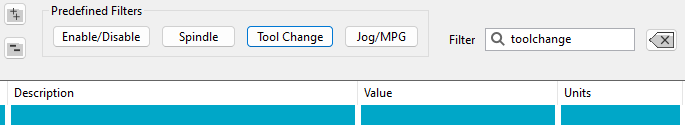
Click the Predefined Filters button for Tool Change.
The first group of settings should match this. The number of pockets will vary from machine to machine.

Next you must decide if you want the tool changer to be outside softlimits in the active axis, if yes set "Disable softlimits" to Yes.

This means that the Y softlimits should stop the machine before the spindle reaches the winerack, this protects against crashes if an improper program is loaded. it can cause a little more headache if you get an error mid toolchange. it also means that the Y end position in the spreadsheet should be set to end the tool change back within the softlimit envelope. the yellow line below shows about where the Y softlimit should be in this case.

The next step is the signal mapping for Drawbar, airpurge, etc. there are available settings for 4 spindles. we are going to just use spindle 1 and tool changer 1 for standard single spindle machines.
the general idea is to map what you have and leave everything else blank, use Mach input and output signals, not direct I/O points. this forces everything through mach's logging which improves future troubleshooting

On a winerack tool changer you will probably only have I/O for the drawbar and maybe a dust shroud.
Here are the drawbar settings as an example.

Drawbar clamp output should be mapped to the solenoid that closes the drawbar (most machines rely on a spring stack to lock the tool, this is rarely used)
Drawbar clamped input should be mapped to the input that senses when the drawbar is retracted, usually this is "closed without tool"
Drawbar input settle time is really handy for timing, settle times are used to delay the next action in the tool change sequence, usually the output fires, then we wait for the associated input to come high, then we advance to the next thing. either the next output or a motion command. if no input is mapped the sequence will advance immediately after firing the output.
it goes like this. Output1->Input1->settle timer->Motion->Output2->input2->settle timer and so on.
Settle timers are nice if you want to wait a bit after the input goes high before advancing, or if you have no input available you can use it to wait long enough for the pneumatic action to take place before doing the next thing.
Drawbar unclamp Output should be mapped to the solenoid that opens the drawbar to release the tool virtually every machine will have this.
drawbar unclamp input should be mapped to the input that tells us that the drawbar is open and the tool can drop free.
Most winerack machines will be using these sections.


The tool release input should be mapped to a tool release button if you have one this will allow you open the drawbar manually to take tools in and out without using the tool changer. if you don't have a button then usually the F1 key on the pendant is a good option.
Pro Tip: all tool changes happen at Rapid so before testing your first tool change lower your rapid override so you have more reaction time in case something is configured incorrectly.
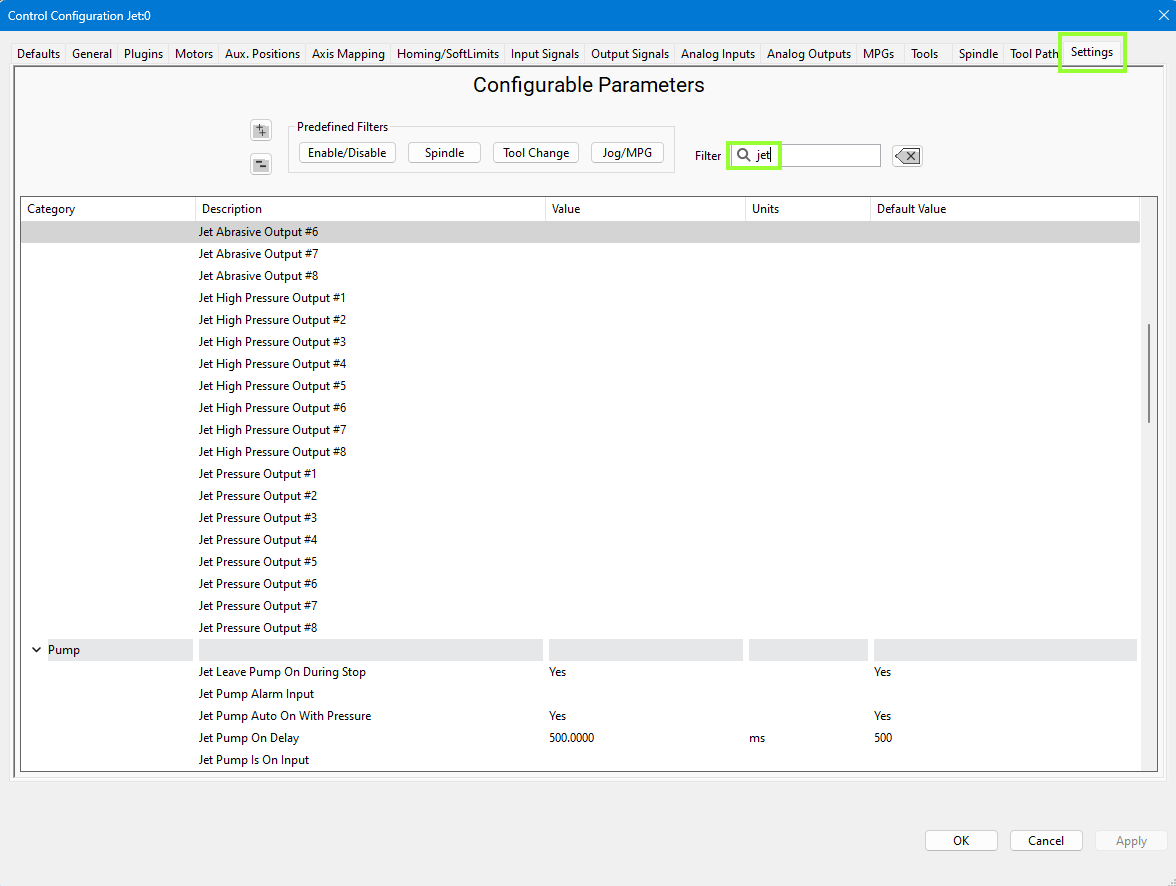
Jet Setup
Configure the number of jets you need and your default delays. Pull down Configure -> Control - Settings.
We set the Jet Abrasive Purge Line Delay at 1250 ms which allows the abrasive to stop flowing just before the water turns off. The Jet Off Delay is set to 250 ms which gives us a slight pause after the water turns off and before it starts moving to the next cut. You may adjust these values to appropriate values for you machine.
IO Setup
Virtually every waterjet will need some of following signals. Map each of the ones you need to the correct output. That is done in the Control screen. Configure -> Control - Output Signals. This example is using the simulator. In operation, the device will be the M31, and the Output Names will be EtherCat device names. (1DO.01.0n). Here we have mapped 3 output signals to specific electrical outputs. From this point forward in the configuration, we will use the signals.
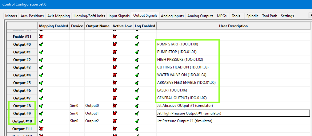
Note that MachPro has a set of pre-defined outputs for your convenience. During configuration of the system, these pre-defined signals need to be mapped to the electrical outputs.
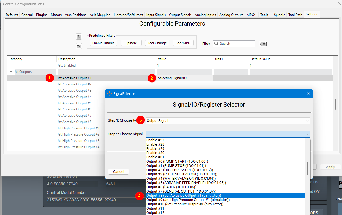
This jet abrasive output is now mapped to a software signal (Output #8). As a software signal, it is now fully accessible to the MachPro software.
| Name | Function | Configuration |
| Jet Abrasive Output(s) | Turns on and off abrasive for the corresponding jet. | Map it to the correct output signal in Mach. |
| Jet High Pressure Output(s) | Turns on and off high pressure for the corresponding jet. Also called things like UHP On/On valve. | Map it to the correct output signal in Mach. |
| Jet Pressure Output(s) | Turns on and off the actual jet. Often called Water On or Jet On. | Map it to the correct output signal in Mach. |
| Jet Pump Output | This turns on the actual intensifier pump. If using a PLC this should trigger the PLC to start the intensifier. Often called Intensifier. | Map it to the correct output signal in Mach. |
For example, Jet Pressure Output #1 here is set to Jet On/Off Solenoid.

Delete everything below this?
The M31 doesn't have enough outputs, but might have enough inputs
The general description of how the PLC would be used might be helpful?
Leave the GMS section?
Remove Analog I/O
Remove PLC setup
Leave cut recovery
Some waterjets may have some of these more advanced IO. This is more for when the intensifier is controlled inside the Mach PLC.
The main sequence to power on the intensifier is as follows:
- Turn on water (Filtered water shutoff valve). This allows water to go to the intensifier.
- Turn on the Bleeddown Valve to prepare the intensifier to run.
- Turn on Boost / Water Inlet Motor. This brings the incoming water up to a low PSI (like 50PSI)
- Wait until INLET WATER PRESSURE SHUTDOWN is active so we know the water pressure is above the base PSI. Often 3-5 seconds to build pressure.
- Turn on the intensifier. Turn on Cooling Water Shutoff valve to keep the water cold.
To turn off the intensifier, the following sequence is used:
- Turn off Intensifier and Cooling Water Shutoff.
- Turn on Bleeddown Valve to let the pressure out of the lines.
- Turn off the boost motor and the water.
Outputs
| Name | Function | Configuration |
| HP Bleed Down Valve |
When the pump turns off this valve must open to let the pressure out of the line. |
By default should be wired to the PLC. |
| Cooling Water Shutoff Valve |
This function keeps the pump cool. Should always be on when the pump is on. |
By default should be wired to the PLC. |
| Filtered Water Shutoff Valve | Allows water to go to the intensifier. It must be on before the intensifier is turned on or it could blow it up. | By default should be wired to the PLC. |
| INTENSIFIER LEFT SHIFT SOLENOID | Moves the hydraulic cylinder to the left. | Must be wired to the PLC and programmed in the PLC. |
| INTENSIFIER Right SHIFT SOLENOID | Moves the hydraulic cylinder to the right. | Must be wired to the PLC and programmed in the PLC. |
| Boost Pump / Water Inlet Motor | A boost pump is used to pressurize the water pressure being fed to the intensifier. It must be on and up to pressure before turning on the intensifier. | By default should be wired to the PLC. |
Inputs
| Name | Function | Configuration |
| Garnet Empty | Tells the operator when to refill the garnet |
Setup in GMS. |
| INTENSIFIER LEFT CHECK VALVE OVERTEMP |
Setup in GMS. | |
| INTENSIFIER RIGHT CHECK VALVE OVERTEMP |
Setup in GMS. |
|
| INTENSIFIER LEFT SHIFT SENSOR |
Must be wired to the PLC and programmed in the PLC. |
|
| INTENSIFIER RIGHT SHIFT SENSOR |
Must be wired to the PLC and programmed in the PLC. |
|
| INLET WATER PRESSURE WARNING |
Setup in GMS. |
|
| INLET WATER PRESSURE SHUTDOWN | This input measures the water pressure at the intensifier after the water inlet motor or pump is on. It must be up to pressure before the intensifier can turn on. |
Setup in GMS. AND must be wired to the PLC to prevent the Intensifier from turning on until this input is off. |
| HP BLEEDDOWN OVERTEMP WARNING |
Setup in GMS. |
|
| HYDRAULIC OIL OVERTEMP WARNING |
Setup in GMS. |
|
| HYDRAULIC OIL OVERTEMP SHUTDOWN |
Setup in GMS. |
|
| HYDRAULIC OIL LEVEL SHUTDOWN |
Setup in GMS. |
For example, a HYDRAULIC OIL OVERTEMP WARNING GMS would be setup as follows:

Some waterjets have a servo controlled Abrasive. For that use these settings:

Cut Recovery
You can configure the axes to move.

