2000 Series Centerless Grinder Operating Manual
{{@672}}
Introduction
This manual is designed to give the operator a working understanding of how to operate your new CNC Centerless Grinder. The control is designed to simplify the operation of your Centerless Grinder high-end features. We have elected not to use g-codes to manipulate the servo axis. Instead, we use the combination of a simplified data entry routine with a graphic interface that the operator will find extremely easy to use.
Using a touch screen interface the operator simply touches the push button to start of stop a function or touch an edit field to change data, directly on the screen.
Each page contains items that are used specifically for the function of the individual screen like starting and stopping motors, changing cycle modes, entering new feedrates and positions, etc.
There are other items that are used globally. This means that the same items are found on all of the pages. Primarily they are the machine state, cycle time, and date and time at the top of the screen, the axis position, cycle status, current feedrate, and wheel speed on the right side of the screen.
Operator Panel Overview
The following is a description of the Operator Panel and it's functional devices. The numbered balloons point to the object.

- Computer HMI. Consists of screens designed to control the machine functions and feedback information on the machine state.
- Emergency Stop Button. Used to stop process and motors in the event of an emergency, by turning off all active output logic.
- Cycle Start Button. Used to initiate an automatic cycle and confirm actions.
- Feedhold Button. Used to pause an automatic cycle in place.
- Cycle Stop Button. Used to stop an automatic cycle in place.
- Reset Button. Used to clear or reset machine faults and enable system servo motors.
- Rapid Speed Control Buttons. Used to change the speed the machine moves during rapid moves.
- Feedrate Override Knob. Used to change the speed the machine moves during feed moves.
- Spindle Control Buttons. Used to start and stop the wheel and change the speed override value.
- Programmable Function Buttons. Used to customize the control.
- Jog Control Buttons. Used to manually jog servo axes while the machine is not in a cycle.
- Jog Speed Knob. Used to control the speed during manual jog moves.

The system includes In-Feed, Thru-Feed and Profile Dressing pages. With the controls familiar windows interface, intuitive graphics, and user friendly layout, the system is easy to learn. Allowing you to have the machine operational almost immediately.
Screen Navigation

- Status
- Status - Displays any current messages (Home All Pressed, Cycle Start Pressed, etc.)
- State - Displays the current state of the machine (Run, Feed Hold, etc)
- Cycle Time - Displays how long the GCode has been running
- Date - Date and time of the timezone of the control
- Operation Pages
- In-Feed Cycle Page

- Thru-Feed Cycle Page

- Grind Wheel - Setup and Dressing Page

- Regulating Wheel - Setup and Dressing Page

- Service
- Maintenance and Support

- Dashboard

- Machine I/O

- Grinder Settings

- Program

- Maintenance and Support
- In-Feed Cycle Page
- Operation Display
- Axis Position Display
- Cycle Status
- Feedrate Display
- Grind Wheel Display
- Regulating Wheel Display
- Grinder Dashboard
- Configurable Dashboard with Widgets for machine auxiliaries (Hydraulics, Mist Collectors etc.)
- Side Bar Dashboard
- Configurable Dashboard with Widgets for productivity


In-Feed Cycle
The In-Feed Grinding cycle begins at the Load Position and rapids to the start of the Coarse grind and continues through Medium and Fine with optional Feedrates and pauses until it reaches the Finish Position and pauses to spark-out. Then rapids to the Retract Position and completes the cycle at the Load Position.
In-Feed Cycle Parameters
Position Parameters

- Retract Position: The position the slide will move to at the end of the cycle to drop or eject the part. When the Retract Position is not needed set the make it equal the Load Position.
- Load Position: This is the first and last slide position in the cycle.
- Finish Position: This is the final grind position and the position that Fine, Medium and Coarse grind amounts are referenced from. The Finish Position can be set to a diameter or 0 depending on the setup.
Cycle Parameters

- Coarse Grind
- Coarse Grind Amount: The amount to be removed at the Coarse Feedrate
- Coarse Feedrate: The Feedrate used during Coarse grind
- T1: Optional Delay at the end of the Coarse grind
- Medium Grind
- Medium Grind Amount: The amount to be removed at the Medium Feedrate
- Medium Feedrate: The Feedrate used during Medium grind
- T2: Optional Delay at the end of the Medium grind
- Fine Grind
- Fine Grind Amount: The amount to be removed at the Fine Feedrate
- Fine Feedrate: The Feedrate used during Fine grind
- T3: Optional Delay at the end of the Fine grind, sometimes referred to as Sparkout Time
- Retract Delay
- T4: Optional Delay at the Retract position to allow the part to drop between the Regulating Wheel and Grinding Wheel
- Load Delay
- T5: Optional Delay at the end of the cycle. This is normally used along with Cycle Repeat to allow time to load the next part.
In-Feed Comp
Comp is used to adjust the part diameter. For more info see Compensation.
At any point Cycle Stop or Retract buttons will cause the slide to Rapid to the Retract Position.
Thru-Feed Cycle
Thru-Feed Grinding will rapid the slide to the Grind Position and stay there.

Thru-Feed Cycle Parameters
- Position Parameters
- Retract Position: The position the slide will move to when Cycle Stop or Retract are used.
- Finish Position: This is the position the slide will move to when the cycle is ran.
Thru-Feed Comp
When the slide is at the Grind Position and Comp offset is applied the slide will move back to the Grind Position. When the slide is at any other position than the Grind Position the slide will apply the offset without any movement. For more info see Compensation.
At any point Cycle Stop or Retract buttons will cause the slide to Rapid to the Retract Position.
Grind Wheel
The Grind Wheel Page is where the Grind Wheel parameters and dress parameters are configured. Depending on the enabled options of the machine some of these parameters will be hidden.

Use the following figure for Grind Wheel dimensions and clearances

Grind Wheel Parameter Descriptions
- Diameter: The current wheel diameter. The dressing cycle automatically updates the wheel diameter. When a new wheel is mounted on the machine this parameter should be updated.
- Minimum Diameter: When the wheel is dressed to this diameter the control will not allow any more dress cycles to complete. The operator will get a alarm messages stating that the wheel is to small.
- Width: The current width of the wheel, used in the straight dressing cycles.
- Minimum Width: When the wheel is side dressed to this width the control will not allow any more dress cycles to complete. The operator will get a alarm messages stating that the wheel is to narrow.
- Clearance Circumference: This is used in the dress cycle, the diamond will rapid to this clearance position and then switch to a feedrate move before touching the wheel.
- Clearance Front Side: This is used in the dress cycle, the diamond will rapid to this clearance position and then switch to a feedrate move before touching the wheel.
- Clearance Back Side: This is used in the dress cycle, the diamond will rapid to this clearance position and then switch to a feedrate move before touching the wheel.
- Max Wheel RPM: Max RPM the wheel can be commanded to run. Check the wheel specs and keep this number under it.
- Wheel SFM: The commanded Surface Feet Per Minute or (SFM). There are buttons just below that set the mode, RPM Mode or SFM Mode.
- Wheel RPM: The commanded Rotations Per Minute or (RPM). There are buttons just below that set the mode, RPM Mode or SFM Mode.
- Wheel Speed Mode: RPM Mode or SFM Mode switch the command source between Wheel RPM and Wheel SFM modes.
Grind Wheel Diamond Setup

- Using the Jog buttons or MPG, Jog the GD (X) axis so the diamond is just touching the front side of the wheel.

- Press the yellow Teach button for X.
- Using the Jog buttons or MPG, Jog the GD (Y) axis so the diamond is just touching the circumference of the wheel.

-
Press the yellow Teach button for Y.
Y Diamond Comp
Diamond Comp can be used at anytime and during a dress cycle to move the diamond in closer to the wheel. Sometimes the wheel will wears a lot between dress cycles, and this can be use to reduce the number of dress passes. For more information see Compensation.

Standard Dress
The Standard Dress is the default dress cycle and would be used after the wheel has been shaped and is ready for production. Standard Dress will use whatever profile was selected on the New Wheel Dress page.

Standard Dress Parameters
- Dress Rate: The feedrate the diamond will travel across the wheel.
- Dress Passes: The number of passes the diamond will make across the wheel.
- Dress Amount: The amount mount of wheel to remove per pass. The amount is in radius of the wheel so 0.001 will change the wheel diameter by 0.002.
- Spark-Out Rate: The feedrate the diamond will travel across the wheel during the Spark-Out Pass or Free Pass.
- Spark-Out Passes: The number of passes the diamond will make across the wheel without in-feeding the diamond into the wheel. Sometimes this type of pass is called a Free Pass.
- In-Feed Parts Per Pass: This is only used in the In-Feed Cycle and will cause the control to automatically call a dress cycle after the number of cycles is greater than the value in this parameter. A value of 0 disables this feature.
New Wheel Dress
The New Wheel Dress is the cycle used to create the profile in the wheel and to rough the wheel into shape.

New Wheel Dress Parameters
- Dress Rate: The feedrate the diamond will travel across the wheel.
- Dress Passes: The number of passes the diamond will make across the wheel.
- Dress Amount: The amount mount of wheel to remove per pass. The amount is in radius of the wheel so 0.001 will change the wheel diameter by 0.002.
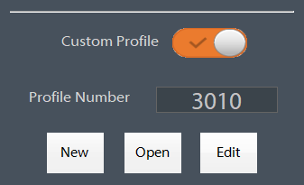
- Custom Profile: When the Custom Profile is off the dress profile will be a straight profile and use the Grind Wheel Parameters to make the profile. When Custom Profile is on there will be a subroutine with a profile that the diamond will follow.
New Wheel Dress - Straight Profile
When the Custom Profile is off the dress profile will be a straight profile and use the Grind Wheel Parameters to make the profile.

New Wheel Dress - Custom Profile
When the Custom Profile is on the the dress cycle will use the Subroutine that is created with the profile number.

Custom Profile
Profile Number shows the selected Profile to use. To change the profile press Open.
There are 3 buttons for creating opening and editing the custom profiles.
- New will open the Grind Wheel Profile Dressing dialog with blank profile.
- Open will open a File Browser dialog and allow you to select a profile.
- Edit will open the current profile in the Grind Wheel Profile Dressing dialog.
Grind Wheel Profile Dressing
The Grind Wheel Profile Dressing is where you create your custom dress profile for the wheel. The profile can be a mixture of lines and arcs. There are four columns Type, X Position, Y Position and Radius showing the data for the given line or arc segment. The example below has profile number 2005 loaded.

Add Line Segment
Remove Line Segment
Use the Remove button to remove any line segment.
Profile Operations
Open: Open a different dress profile
Add: Add new line segment to the dress profile
Remove: Remove a line segment from the dress profile
Save As: Save the profile with a new name
Save: Save the current profile
Regulating Wheel
The Regulating Wheel Page is where the Regulating Wheel parameters and dress parameters are configured. Depending on the enabled options of the machine some of these parameters will be hidden.

Use the following figure for Regulating Wheel dimensions and clearances

Regulating Wheel Parameter Descriptions
- Diameter: The current wheel diameter. The dressing cycle automatically updates the wheel diameter. When a new wheel is mounted on the machine this parameter should be updated.
- Minimum Diameter: When the wheel is dressed to this diameter the control will not allow any more dress cycles to complete. The operator will get a alarm messages stating that the wheel is to small.
- Width: The current width of the wheel, used in the straight dressing cycles.
- Minimum Width: When the wheel is side dressed to this width the control will not allow any more dress cycles to complete. The operator will get a alarm messages stating that the wheel is to narrow.
- Clearance Circumference: This is used in the dress cycle, the diamond will rapid to this clearance position and then switch to a feedrate move before touching the wheel.
- Clearance Front Side: This is used in the dress cycle, the diamond will rapid to this clearance position and then switch to a feedrate move before touching the wheel.
- Clearance Back Side: This is used in the dress cycle, the diamond will rapid to this clearance position and then switch to a feedrate move before touching the wheel.
- Max Wheel RPM: Max RPM the wheel can be commanded to run. Check the wheel specs and keep this number under it.
- Wheel SFM: The commanded Surface Feet Per Minute or (SFM). There are buttons just below that set the mode, RPM Mode or SFM Mode.
- Wheel RPM: The commanded Rotations Per Minute or (RPM). There are buttons just below that set the mode, RPM Mode or SFM Mode.
- Wheel Speed Mode: RPM Mode or SFM Mode switch the command source between Wheel RPM and Wheel SFM modes.
Regulating Wheel Diamond Setup
- Using the Jog buttons or MPG, Jog the RD (Z) axis so the diamond is just touching the front side of the wheel.

- Press the yellow Teach button for Z.
- Using the Jog buttons or MPG, Jog the RD (A) axis so the diamond is just touching the circumference of the wheel.

-
Press the yellow Teach button for A.
Standard Dress
The Standard Dress is the default dress cycle and would be used after the wheel has been shaped and is ready for production. Standard Dress will use whatever profile was selected on the New Wheel Dress page.
Standard Dress Parameters
- Dress Rate: The feedrate the diamond will travel across the wheel.
- Dress Passes: The number of passes the diamond will make across the wheel.
- Dress Amount: The amount mount of wheel to remove per pass. The amount is in radius of the wheel so 0.001 will change the wheel diameter by 0.002.
- Spark-Out Rate: The feedrate the diamond will travel across the wheel during the Spark-Out Pass or Free Pass.
- Spark-Out Passes: The number of passes the diamond will make across the wheel without in-feeding the diamond into the wheel. Sometimes this type of pass is called a Free Pass.
- In-Feed Parts Per Pass: This is only used in the In-Feed Cycle and will cause the control to automatically call a dress cycle after the number of cycles is greater than the value in this parameter. A value of 0 disables this feature.
New Wheel Dress
The New Wheel Dress is the cycle used to create the profile in the wheel and to rough the wheel into shape.
New Wheel Dress Parameters
- Dress Rate: The feedrate the diamond will travel across the wheel.
- Dress Passes: The number of passes the diamond will make across the wheel.
- Dress Amount: The amount mount of wheel to remove per pass. The amount is in radius of the wheel so 0.001 will change the wheel diameter by 0.002.
- Custom Profile: When the Custom Profile is off the dress profile will be a straight profile and use the Regulating Wheel Parameters to make the profile. When Custom Profile is on there will be a subroutine with a profile that the diamond will follow.
New Wheel Dress - Straight Profile
When the Custom Profile is off the dress profile will be a straight profile and use the Regulating Wheel Parameters to make the profile.
New Wheel Dress - Custom Profile
When the Custom Profile is on the the dress cycle will use the Subroutine that is created with the profile number.
Custom Profile
Profile Number shows the selected Profile to use. To change the profile press Open.
There are 3 buttons for creating opening and editing the custom profiles.
- New will open the Regulating Wheel Profile Dressing dialog with blank profile.
- Open will open a File Browser dialog and allow you to select a profile.
- Edit will open the current profile in the Regulating Wheel Profile Dressing dialog.
Regulating Wheel Profile Dressing
The Regulating Wheel Profile Dressing is where you create your custom dress profile for the wheel. There are four columns Type, Z Position and A Position showing the data for the given line segment. The example below has profile number 3010 loaded.

Add Line Segment
Remove Line Segment
Use the Remove button to remove any line segment.
Profile Operations
Open: Open a different dress profile
Add: Add new line segment to the dress profile
Remove: Remove a line segment from the dress profile
Save As: Save the profile with a new name
Save: Save the current profile
Operations
Before Running A Part
Before running parts on the control, be sure the following steps have happened after starting the control software:
- Machine is homed
- Dresser diamond positions have been taught
- Wheel has been rough dressed
- Wheel has been calibrated to the part
- Flagging device has been calibrated to the wheel
Homing Machine
Most machines are configured with a Enable and Home dialog that will be shown on startup.

Press the Cycle Start button on the dialog or the Cycle Start button on the operator panel. The machine will enable the servos and home to the switches.
If for some reason this dialog is not shown you can manual enable the machine by pressing Reset and then navigate to the Service page.

Home each axis individually or press Home All to home all axes.
Grind Wheel Dresser Setup
- Using the Jog buttons or MPG, Jog the GD (X) axis so the diamond is just touching the front side of the wheel.
- Press the yellow Teach button for X.
- Using the Jog buttons or MPG, Jog the GD (Y) axis so the diamond is just touching the circumference of the wheel.
-
Press the yellow Teach button for Y.
Rough Dress
After the dresser is setup a rough dress program needs to be run to true up the wheel before calibrating the wheel to the part. Use the Conversational to create a dress program that will profile and true the wheel. Re-run this program until the diamond touches all the way across the wheel.
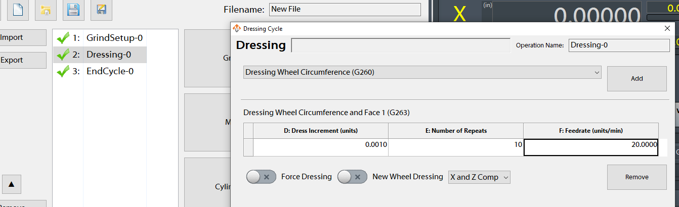
See Dress Cycles to learn more about creating a dress program.
Calibrating the Wheel to the Part
Initial calibration of the wheel to the part must always be done if the dresser positions are modified!
X Calibration
- Mount a scrap part into the machine and turn on the Wheel Head and Work Head.
- Using the Jog buttons or MPG, Jog the wheel so the circumference of the wheel is just touching the part and then continue jogging until the wheel has trued up the part and is making contact all the way around.
- Press the yellow Teach X button and then jog off and away from the part to a safe distance.
- Stop the Work Head and Wheel Head.
- Using a precision measuring device, measure the diameter of the newly ground surface.
- Enter the diameter into the Measured X box and press enter.
- Press the orange Update button.

Z Calibration (With One Wheel)
- Mount a scrap part into the machine and turn on the Wheel Head and Work Head.
- Near the bottom of the page is the Tool Offsets group. Type "0.0" into the "Z Offset" and into the "Z Wear Offsets" boxes.
- Using the Jog buttons or MPG, Jog the wheel so the face of the wheel is just touching the shoulder of the part and then continue jogging until the wheel has trued up the shoulder and is making contact all the way around.
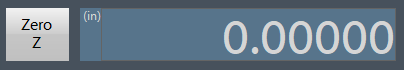
- Press the grey Zero Z button near the Z Position DRO.
Z Calibration (With Multiple Wheels)
Follow the "Z Calibration (With One Wheel)" steps on the master wheel.
- Mount a scrap part into the machine and turn on the Wheel Head and Work Head.
- Using the Jog buttons or MPG, Jog the wheel so the face of the wheel is just touching the shoulder of the part and then continue jogging until the wheel has trued up the shoulder and is making contact all the way around.
- Press the yellow Teach Z button and then jog off and away from the part to a safe distance.
- Stop the Work Head and Wheel Head.
- Using a precision measuring device measure the position of the shoulder of the newly ground surface.
- Enter the diameter into the Measured Z box and press enter.
- Press the orange Update button.

Use the X Correction and Z Correction fields to adjust the part positions by distance values and pressing Update
Calibrating the Flag to the Wheel
Calibration of the Flag must be done if the dresser positions are modified!
Calibrating the Flag will setup the Z offsets between the wheel Face #1 and the Flag probe. Calibration needs to be done anytime a wheel dresser is re-setup. You must calibrate the Flag to the same shoulder that was used to calibrate the Z side of the wheel the previous step. (Calibrating the Wheel to the Part)

Calibration Wizard
Follow the instructions on the calibration pages to calibrate the Flag to the wheel

Loading a Job to Run
Creating a New Conversational Job
- Navigate to the Conversational page
- Press the icon for a new file, near the top left corner

- Add cycles to the job
- Press the Post button near the bottom left corner to save and load the job for execution

Loading a Conversational Job for Edit
- Navigate to the Conversational page
- Press the icon for load file, near the top left corner

- Use the File Navigator window to select the job for edit
The file extension must be .ini
The job file must have been previously created by the conversational page
- Double-click on cycles to edit them or add more cycles to the job
- Press the Post button near the bottom left corner to save and load the job for execution

Flagging Device Initial Setup
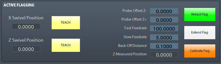
- Jog the X and Z axis to a safe position for the flag to use as the Swivel Position and press the two yellow TEACH buttons.
- Enter the appropriate feedrate to be used on the initial search for the shoulder into the DRO labeled Fast Feedrate.
- Enter the appropriate feedrate to be used on the final search for the shoulder into the DRO labeled Slow Feedrate.
- Enter the appropriate distance for the probe to back away from the shoulder on the second touch into the DRO labeled Back-Off Distance.
- The Probe offsets Z+/- are used to shift the probe position +/- based on the probe move direction.

These 3 positions (Finish Position, Load Position, Retract Position) must be calibrated and setup prior to running the cycle.
- Setup the distance between the Regulating wheel and
- Using the Jog buttons or MPG, Jog the wheel so the circumference of the wheel is just touching the diamond in the X axis direction.
Appendix
Start-Up Sequence
- Apply power to the control
- Press the Reset button on the operator panel. The control will go through it's start-up sequence. Allow time for the computer to start up.
- Start the Mach4 application from the shortcut on the desktop. Allow time for the system to initialize.
- Press Cycle Start when the control requests to enable and home the servo axes.
Homing
To home the machine, begin by pressing the [Reset] button. Then navigate to the [Service/Maintenance] tab and press [Home All]. There is an optional parameter to prompt the user to home the machine on startup.
Programmed Movement
MDI
To command a movement using the MDI feature, press the [MDI] button.


Compensation
Compensation or Comp is used to adjust the slide offsets to maintain the part diameter as the wheel breaks down and wears. It can also be used to adjust the diamonds closer to the wheel while dressing. Comp acts differently depending on the grinding mode. See the table below to see how Comp is applied.
| Grinding Mode | Adjust slide offsets? | Moves to position after adjustment? |
| In-Feed Grinding | Yes |
No |
| Thru-Feed Grinding at Grind Position | Yes | Yes |
| Thru-Feed Grinding not at Grind Position | Yes | No |
There are Comp buttons on the screen, and some machines have buttons on panels for applying Comp. Coarse and Fine Comp buttons allow the operator to choose between two defined increment sizes.

Total Comp
Total Comp is for the operator to track how much Comp as been applied. Resting the Total Comp will only zero the Total Comp indicator.
Configure Comp Amount
Coarse and Fine Comp amounts are configurable on the Service / Grinder Settings page.

Backlash Move
When Comp is being applied and the slide is moving away from the grinding wheel the control can make an extra move to take up any loss of motion from backlash in the slide. To enable this option open the Interface Config dialog from the Service page and search for Backlash. Modify the following parameters.
- Backlash Move Enabled: This enables and disables the Backlash move
- Backlash Move Distance: This is the distance the slide will move when applying Comp
{{@677}}