X15-72-01 Pedestal Stand Mounting Instructions
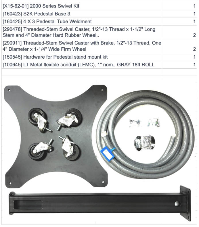
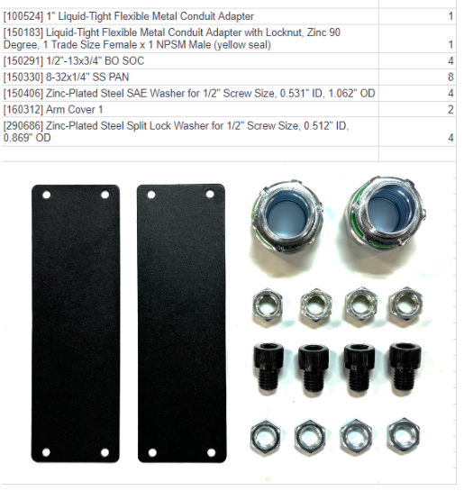
Parts list for Pedestal Stand
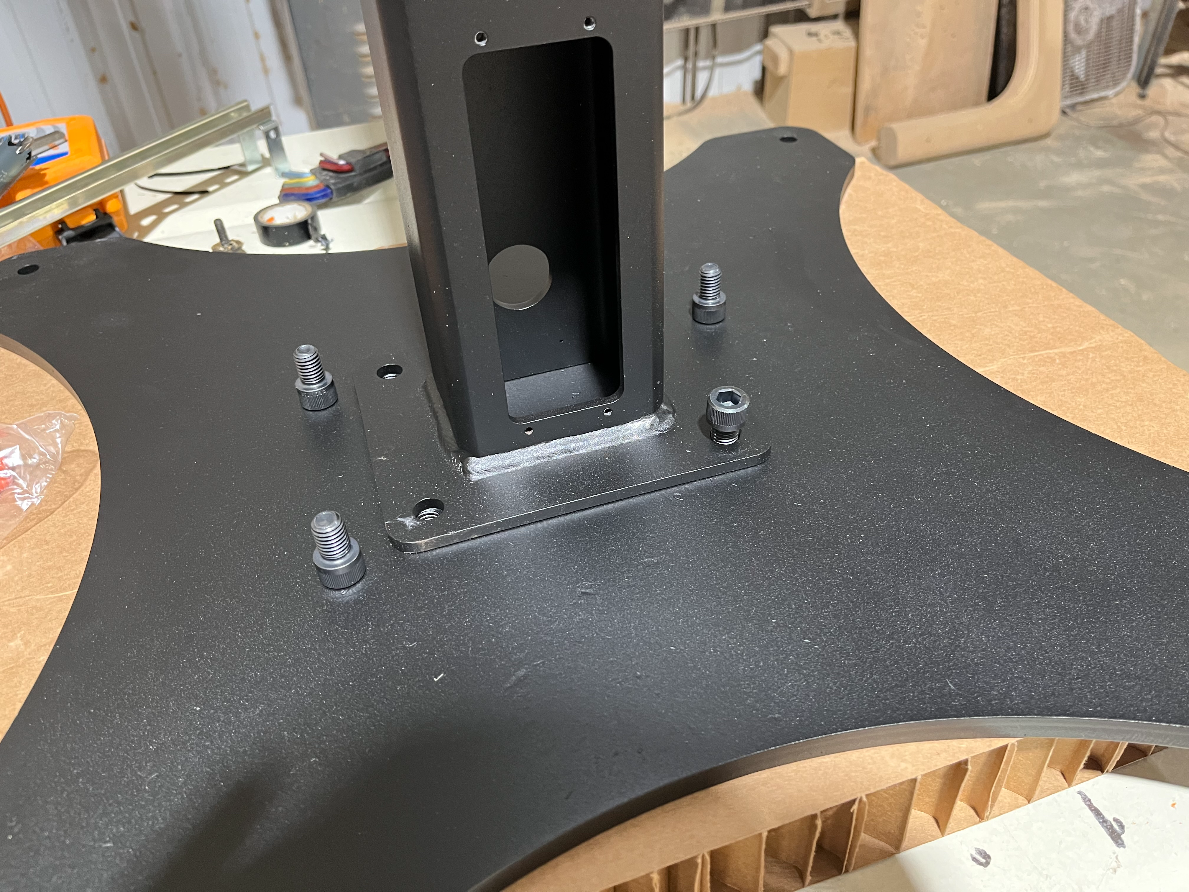
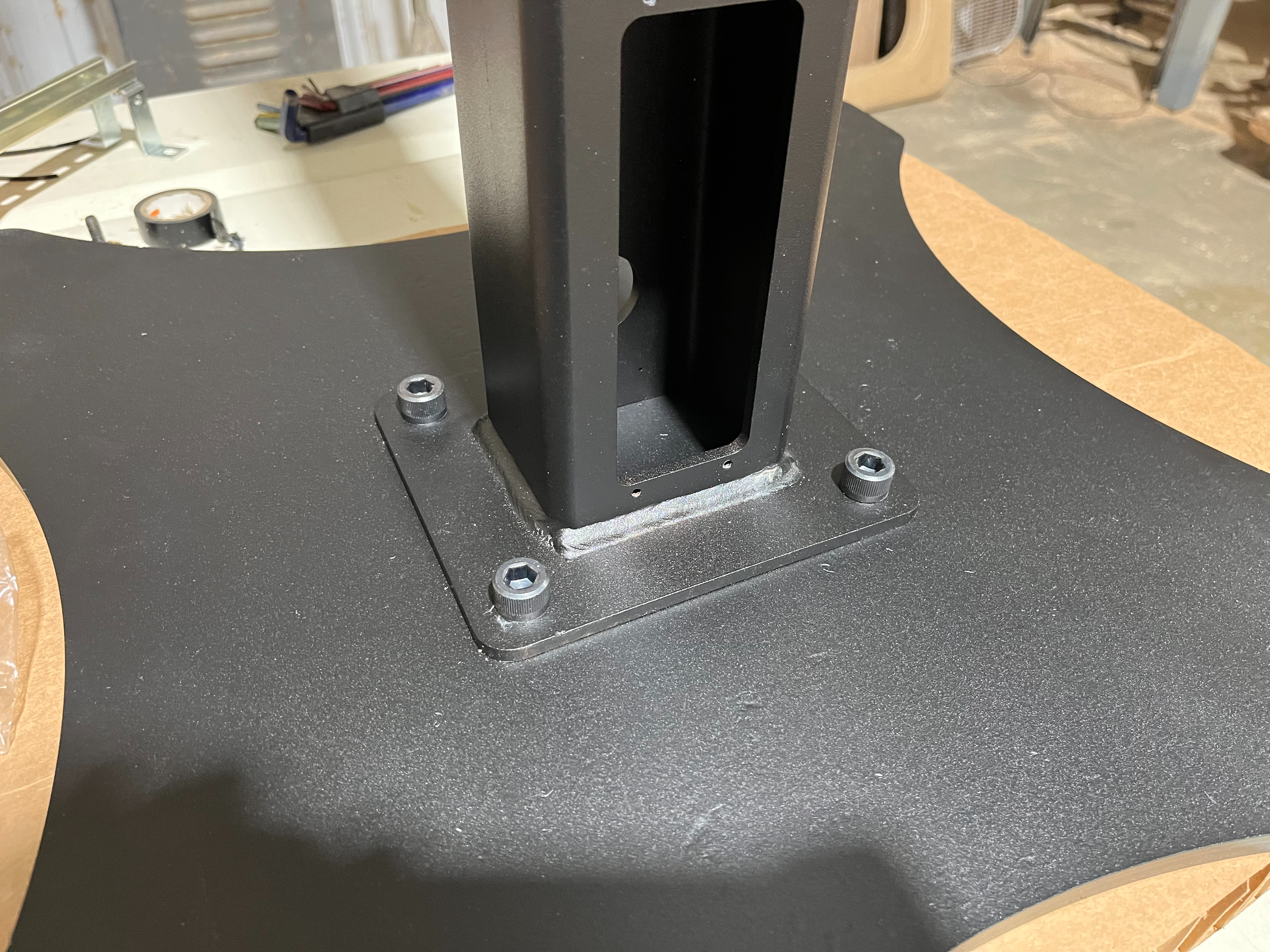
1) Mount the pedestal to the base using the provided ½”1/2"-1313x3/4 x 3⁄4” buttonsocket head cap screws using a 5/16” allen wrench tobolts 80 ft lb.
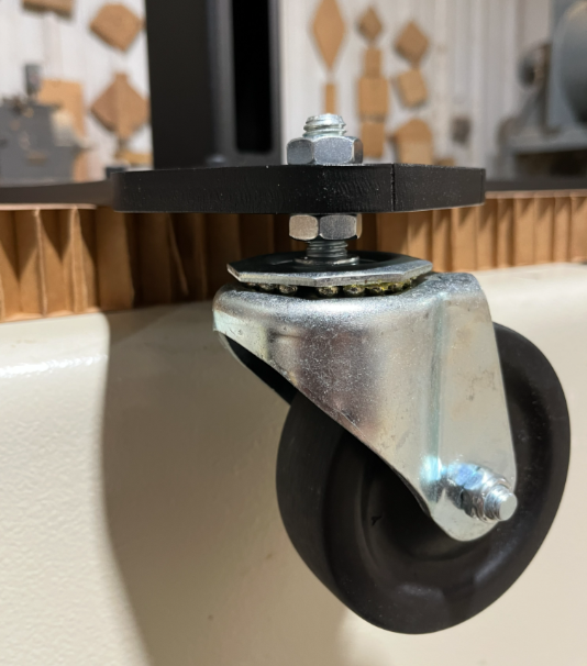
- Install provided conduit connector on the bottom of the pedestal. Next Install the 4 casters, using the provided Nuts and washers as shown below. Adjust the caster nuts as needed to level the wheels and ensure stable, even contact with the floor.

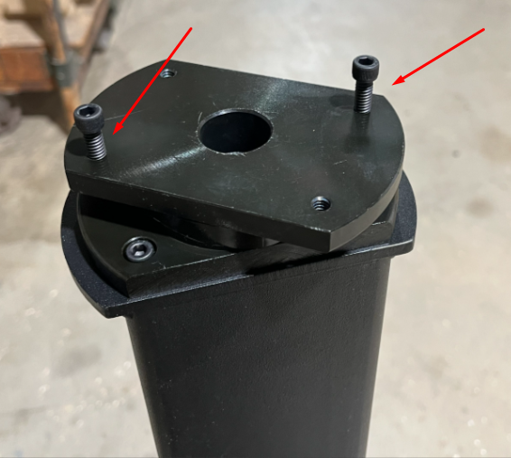
2) Place the swivel on the top of pedestal with the countersunk bolt holes on the bottom and secure with the provided ¼”-20 x 0.75” socket head cap screws using a 3/16” allen wrench.
- To
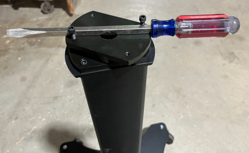
Placemake bolt access easier, temporarily install two bolts in the top of the swivel, as shown in the diagram below. Use a screwdriver or similar tool to rotate the upper portion of the swivel to align and access the mounting holes. Once the swivel is secured, place the strain relief plate on top of the swivel.

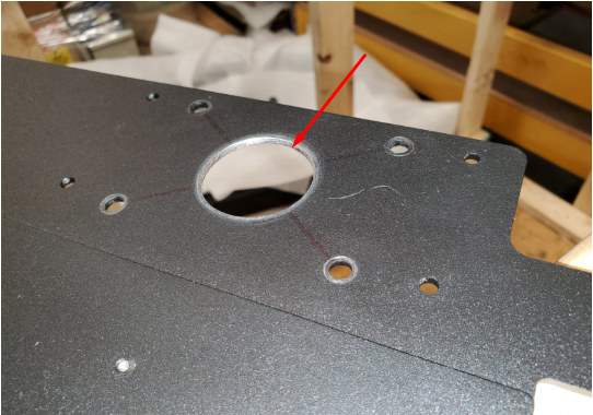
3) Locate the cable pass through knockout on the keyboard tray mount and knock out.

4) Mount the keyboard tray mount with the supplied ¼”-20 x 0.75” socket head cap screws, sandwiching the strain relief plate in the middle, using a 3/16” allen wrench.

5) LayPlace the control unit on it’sits back on a cleanclean, protected surface andto locateprevent damage. Locate the four (4) knockouts on the bottom aroundof the cablecontrol, pass through hole insurrounding the center gentlycable knockoutpass-through hole. Carefully remove the holes.knockouts

6) Place the control onunit onto the keyboard tray mountmount, and locatealigning the bolt heads intowith the knockoutsknockout onholes in the bottom of the control.
- It
- is recommended to have a second person hold the control in place during this step. While
steadyingstabilizing the control, insertand tightenthe provided eight (8) 8-32 screwsonthrough the bottomthruof the keyboard tray mountinto the control using a phillips screwdriver.

Remove the upper and lower access panels from the back of the control.Remove the WiFi antenna from the heat sinkThru the bottom access opening on the back of the control, unplug the bottom USB extension cable, wireless MPG pendant antenna USB connection, and unscrew the wing nut and remove the ground wire from the PC pan

7) Unscrew the six (6) 8-32 screws on the back of the control that hold the heat sink using a 9/64” allen wrench.
While steadying the front panel and monitor assembly, unscrew the eight (8) 8-32 low profile screws using a 7/64” allen wrench that holds the front panel and monitor assembly in place.
9) Lay the front panel and monitor assembly on its heat sink on a clean protected surface.

10) Route the power cable, Ethernet cables and e-stop cables through conduit and through the conduit connector on the bottom of the pedestal.
Use access openings on bottom and top of pedestal to route cables through.Pull cables through the center of the top swiveland into theenclosure.control, then tighten securely using a Phillips screwdriver.Measure 22” of cable length and zip tie the cables to the strain relief plate.Route cables up and zip tie through the holes on the left hand side of the backbone.Lay the cables through the upper access cover on the back of the enclosure.

11) Replace the front panel and monitor assembly and tighten screws.
Reinstall screws in heat sink.Replace bottom USB extension cable,wireless MPG pendant antenna USB connection, ground wire on PC pan through bottom access cover.

Replace WiFi antennaFollow diagram inside the upper access cover opening and wire accordingly.

12) Replace upper and lower access covers on control and tighten.
Place upper and lower access covers on pedestal and tighten with provided 8-32 screws.