Mach Vision System
Introduction
Overview
The Vision system lets a Mach-controlled CNC use a smart camera to find printed fiducial marks and either (a) report their offset for downstream G-code or (b) automatically align an entire program to a part by capturing a few marks and applying a modal coordinate transform.
The implementation is driver-based. VisionModule owns all calibration math, fit solving, G-code emission, and OEM-parameter wiring; individual driver classes (currently only Keyence, for VS-series smart cameras such as the VS-L320MX) handle the wire protocol. New cameras are added by writing a new driver, not by changing the M-code surface.
All pixel-to-machine-units math, fit solving, and modal G-code (G51 / G68 / G52) emission live in VisionModule. Drivers are dumb — they trigger the camera and return pixel deviations.
Components
| File | Purpose |
Modules/Addons/Vision/VisionModule.lua |
Top-level orchestrator. Calibration (K matrix), alignment-run state, fit solving, modal G-code emission, OEM-parameter wiring, pound-var output. |
Modules/Addons/Vision/VisionMath.lua |
Pure-math helpers: pixel → machine-unit transform (ApplyK), 3-point similarity fit, 4-point rectangle fit, Procrustes / least-squares solvers. |
Modules/Addons/Vision/Drivers/KeyenceVisionDriver.lua |
Keyence VS-series Non-Procedural TCP client. Implements Trigger, SelectJob, GrabImage, Capabilities. |
Modules/CommonMCodeModule.lua |
Hosts the _m280, _m281, _m282, _m283, _m284 implementations. |
Profiles/Mill/Macros/m280.mcs … m284.mcs |
G-code macro wrappers that forward into the implementations. |
Profiles/Mill/Settings/Standard/Common/settings.Vision.csv |
OEM parameter definitions (Connection, Calibration, Output sections). |
M-Code Summary
| M-code | Purpose |
| M280 | Begin an alignment run. Clears the dot list and cancels any active G51 / G68 / G52. Optional P selects fit mode (4 = rectangle, 3 = similarity). |
| M281 | Capture one mark. Triggers the camera, applies the K matrix, stores the observed point in pound vars and the dot list. Optional D1 persists the FTP-pushed inspection image. |
| M282 | Solve and apply the fit as modal G51 / G68 / G52. Optional P selects which piece of the fit to emit (1 = shift, 2 = rotation, 3 = scale, omitted = all). |
| M283 | Calibrate the K matrix. Q = quick diameter calibration (no motion). C = full cal-sheet walk (recommended). |
| M284 | Select the active camera job/program (capability-gated — only drivers that advertise select_job support this). |
System Architecture
Data Flow
- Driver Trigger. The active driver fires the camera and returns a pixel deviation
(dx_px, dy_px)in its native frame (typically top-left origin). - Image-center shift.
VisionModule.CenterRawPixels()subtracts(resX/2, resY/2)using the OEM-configured camera resolution so all internal pixel coordinates are signed offsets from image center. - Camera-vs-machine axis remap. Three OEM toggles —
VisionCameraSwapXY,VisionCameraInvertX,VisionCameraInvertY— normalize the camera frame to the machine frame.M283auto-detects and writes these the first time you calibrate. - K matrix.
VisionModule.PxToMachine()applies the calibrated 2x2 K matrix to convert pixels to machine units (in or mm). K captures combined scale, axis-swap residual, and small rotation between the camera and the machine. - Observed point.
observed = commanded + K*(px - px_center_offset). The commanded XY is read frommcAxisGetPosat trigger time. - Fit. When
M282runs,VisionMath.RectangleFit(4-point) orVisionMath.SimilarityFit(3-point) solves a rigid-body transform from commanded → observed. - Apply.
M282emits the solved transform as modalG52(shift),G68(rotation), andG51(scale) viamcCntlGcodeExecuteWait. The rest of the program runs in the corrected frame.
Tool-Table Convention
The camera is treated as a tool. M283 C writes the camera-vs-spindle X/Y offsets directly into the tool table for the camera tool number, so the machine knows where the camera is relative to the spindle. The convention is:
- Activate the spindle tool. Jog over the cal-sheet center and zero work-coord X and Y.
- Tool-change (
Tn M6) to the camera tool. Jog so the start dot is in the FOV. - Run
M283 C1. The routine walks the sheet, solves K, and writes the camera tool's X/Y offsets so that with the camera tool active a commanded XY puts the camera — not the spindle — at that XY.
VisionCameraToolNumber must match the tool number you use for the camera. When set, every M280 / M281 / M282 / M283 verifies that this tool is the active spindle tool and aborts otherwise — this stops captures from running with the wrong tool offset in effect. Set it to 0 to disable the check.
Camera Setup (Keyence)
Network Configuration
- Default IP:
192.168.208.80— configurable viaVisionIP. - TCP port:
8500(Non-Procedural data output) — configurable viaVisionPort. - Socket timeout:
3seconds — configurable viaVisionTimeout. - End delimiter:
CR(0x0D). Module assumes this.
VS Creator Job Requirements
- Camera must be in Run Mode.
- Trigger source = Communication / Command so
TRGinitiates a measurement. - Configure a Data Output (Non-Procedural) tool emitting comma-separated fields. Either of these formats is accepted:
dx,dyjudgment,dx,dyjudgment,count,dx,dy,width,height,angle,score(full form — recommended for cal sheet)
- For
M283 Qand image saving viaM281 D1, the camera must be configured to FTP-push inspection images to a folder reachable from Mach. - End delimiter = CR.
Image Folder (optional)
Set VisionImageWatchDir to the folder the camera FTP-pushes images into. M281 D1 looks for an image newer than the trigger timestamp and copies it into Modules/Addons/Vision/Images/ with a timestamped filename. VisionImageGrabTimeout (default 2 s) controls how long the watch loop waits.
The 8500 protocol cannot toggle FTP push from the controller, so leave camera FTP push enabled at the camera side and let the D flag on M281 decide whether each frame is kept.
OEM Parameters
Connection
| Name | Type | Default | Description |
VisionEnabled |
yesno | No | Master enable. No = M-codes log a warning and return success without contacting the camera. |
VisionDriver |
choice | Keyence | Driver name. Selects which class under Vision/Drivers/ is loaded. |
VisionIP |
text | 192.168.208.80 | Camera IP address. |
VisionPort |
integer | 8500 | TCP port. |
VisionTimeout |
integer | 3 | Socket I/O timeout (seconds). |
VisionActiveJob |
integer | 0 | Camera program/job id. Persistent; written by M284. 0 = leave camera on whatever job it has loaded. |
VisionImageWatchDir |
text | (empty) | Folder the camera FTP-pushes images into. Empty disables image grab. |
VisionImageGrabTimeout |
float | 2 | Seconds to wait for a fresh image to appear in the watch dir. |
VisionCameraSwapXY |
yesno | No | Swap camera X and Y axes. Auto-set by M283. |
VisionCameraInvertX |
yesno | No | Negate camera X. Auto-set by M283. |
VisionCameraInvertY |
yesno | No | Negate camera Y. Auto-set by M283. |
VisionTriggerSettleSec |
float | 0.25 | Pre-trigger dwell used by M283 only. Lets servo motion settle before capture. |
VisionCameraToolNumber |
integer | 0 | Camera tool number. M280 / M281 / M282 / M283 require this tool be active. 0 disables the check. |
Calibration
| Name | Type | Default | Description |
VisionCal_K11 |
float | 0 | K matrix row 1 col 1 (px → machine units). |
VisionCal_K12 |
float | 0 | K matrix row 1 col 2. |
VisionCal_K21 |
float | 0 | K matrix row 2 col 1. |
VisionCal_K22 |
float | 0 | K matrix row 2 col 2. |
VisionCal_Date |
text | (empty) | ISO timestamp of the last successful calibration. |
VisionCal_Units |
choice | in | Units the K matrix is in (in or mm). |
VisionCameraResX |
integer | 1776 | Camera image width in pixels. |
VisionCameraResY |
integer | 1776 | Camera image height in pixels. |
VisionPxCenterOffsetX |
float | 0 | Optional sub-pixel correction applied after image-center shift, before K. |
VisionPxCenterOffsetY |
float | 0 | Same, Y. |
Output
| Name | Type | Default | Description |
VisionPoundVarBase |
integer | 500 | Base address of the pound-var output block (slot 0 at base, photo count at base+8, indexed point slots at base+20..base+51). See Pound Variables. |
Runtime / Last Trigger (read-only)
These are written by the module after every trigger and run. Surface them as DROs on the screen for diagnostics.
| Name | Type | Description |
VisionLastJudgment |
float | 1 = OK, 0 = NG, -1 = unknown / not reported. |
VisionLastOffsetPxX |
float | Last centered pixel X offset. |
VisionLastOffsetPxY |
float | Last centered pixel Y offset. |
VisionLastOffsetX |
float | Last machine-unit X offset (K * px). |
VisionLastOffsetY |
float | Last machine-unit Y offset. |
VisionLastWidth |
float | Detected mark width in current machine units (in or mm). |
VisionLastHeight |
float | Detected mark height in current machine units. |
VisionLastAngle |
float | Detected mark angle (deg, 0 if N/A). |
VisionLastScore |
float | Driver-reported correlation/score. Clamped to a minimum of 1 for any successful capture. |
VisionLastStatus |
text | OK or human-readable error text. |
VisionRun_Active |
float | 1 while a run is in progress, 0 otherwise. |
VisionRun_Mode |
integer | 4 = rectangle, 3 = similarity. |
VisionRun_DotCount |
integer | Captures taken so far in this run. |
VisionRun_Tx / _Ty |
float | Solved shift (G52). |
VisionRun_Theta |
float | Solved rotation (radians, G68 R). |
VisionRun_Sx / _Sy |
float | Solved scale (G51). |
VisionRun_CenterX / _CenterY |
float | Rotation center (G68 X / Y). |
Pound-Variable Output
Every M281 writes the captured point into a fixed pound-variable block based at VisionPoundVarBase (default 500). Slot 0 (the most recent capture) sits at base+0..base+7. A photo-count var sits at base+8 (#508 by default), leaving base+9..base+19 free for future single-value fields. The four indexed point slots (1–4) begin at base+20, each 8 vars wide, ending at base+51. Slot 0 is always the most recent capture (mirrored from whichever indexed slot just got written); slots 1–4 hold the four M281 captures in the order they were taken during the current run.
For a non-default VisionPoundVarBase — call it B — replace 500 below with B. Slot 0 field f is at #(B + f); the photo count is at #(B + 8); indexed point n (1–4) field f is at #(B + 20 + 8*(n-1) + f).
| Address | Slot | Field | Description |
#500 |
0 (latest) | X | Observed X of the most recent capture, in machine units (commanded_x + dx_units). Mirrored from the slot that was just written. |
#501 |
0 (latest) | Y | Observed Y of the most recent capture, in machine units. |
#502 |
0 (latest) | Width | Detected feature width of the most recent capture, in current machine units (driver pixels × X-axis K column norm). |
#503 |
0 (latest) | Height | Detected feature height of the most recent capture, in current machine units. |
#504 |
0 (latest) | Angle | Detected angle of the most recent capture, in degrees. 0 if the camera job does not report angle. |
#505 |
0 (latest) | Score | Driver-reported correlation / match score for the most recent capture. Clamped to a minimum of 1 for any successfully captured point, so a populated slot is always distinguishable from a cleared (#0 / null) slot. |
#506 |
0 (latest) | reserved | Reserved for future use (planned: Z height). |
#507 |
0 (latest) | reserved | Reserved for future use (planned: detected area). |
#508 |
— | Photo count | Number of M281 captures (photos) taken since the last M280. Reset to 0 by M280 and incremented by every M281. Placed right after slot 0 so it is easy to read alongside the latest capture. |
#509–#519 |
— | reserved | Reserved for future single-value fields. Left as the value of pound var #0 by M280; the module does not write these. |
#520 |
1 (point 1) | X | Observed X of the first M281 capture in this run, machine units. |
#521 |
1 (point 1) | Y | Observed Y of the first M281 capture, machine units. |
#522 |
1 (point 1) | Width | Detected width at point 1, machine units. |
#523 |
1 (point 1) | Height | Detected height at point 1, machine units. |
#524 |
1 (point 1) | Angle | Detected angle at point 1, degrees. |
#525 |
1 (point 1) | Score | Driver score at point 1. |
#526 |
1 (point 1) | reserved | Reserved (planned: Z). |
#527 |
1 (point 1) | reserved | Reserved (planned: area). |
#528 |
2 (point 2) | X | Observed X of the second M281 capture, machine units. |
#529 |
2 (point 2) | Y | Observed Y of the second M281 capture, machine units. |
#530 |
2 (point 2) | Width | Detected width at point 2, machine units. |
#531 |
2 (point 2) | Height | Detected height at point 2, machine units. |
#532 |
2 (point 2) | Angle | Detected angle at point 2, degrees. |
#533 |
2 (point 2) | Score | Driver score at point 2. |
#534 |
2 (point 2) | reserved | Reserved (planned: Z). |
#535 |
2 (point 2) | reserved | Reserved (planned: area). |
#536 |
3 (point 3) | X | Observed X of the third M281 capture, machine units. |
#537 |
3 (point 3) | Y | Observed Y of the third M281 capture, machine units. |
#538 |
3 (point 3) | Width | Detected width at point 3, machine units. |
#539 |
3 (point 3) | Height | Detected height at point 3, machine units. |
#540 |
3 (point 3) | Angle | Detected angle at point 3, degrees. |
#541 |
3 (point 3) | Score | Driver score at point 3. |
#542 |
3 (point 3) | reserved | Reserved (planned: Z). |
#543 |
3 (point 3) | reserved | Reserved (planned: area). |
#544 |
4 (point 4) | X | Observed X of the fourth M281 capture, machine units. Used as the fourth fiducial in a 4-point rectangle fit. |
#545 |
4 (point 4) | Y | Observed Y of the fourth M281 capture, machine units. |
#546 |
4 (point 4) | Width | Detected width at point 4, machine units. |
#547 |
4 (point 4) | Height | Detected height at point 4, machine units. |
#548 |
4 (point 4) | Angle | Detected angle at point 4, degrees. |
#549 |
4 (point 4) | Score | Driver score at point 4. |
#550 |
4 (point 4) | reserved | Reserved (planned: Z). |
#551 |
4 (point 4) | reserved | Reserved (planned: area). |
VisionPoundVarBase must be ≥ 100 and must not overlap Mach's reserved ranges (5061..5081 probe results, 5201..5500 fixture offsets). The module validates this on every M280 and aborts with a clear error if misconfigured.
In a 3-point similarity run (M280 P3), only slots 1, 2, and 3 are populated — slot 4 is left at its previous-run value. Slot 0 still mirrors whichever capture was most recent.
M280 — Begin Alignment Run
Overview
Starts a new alignment run. Clears the in-memory dot list, validates the pound-var base, verifies the camera tool is active, and emits G69 G50 G52 X0 Y0 to cancel any active rotation/scale/shift modal that a previous alignment may have left set. It also clears the entire pound-var output block (base..base+51, i.e. slot 0, the photo-count var, the reserved gap, and the four indexed point slots) by setting every var to the value of pound var #0 (Mach's null variable), and resets the photo counter to 0.
Parameters
| Letter | Description |
| P | Fit mode (optional).4 or omitted = 4-point rectangle fit (recovers shift, rotation, X/Y scale).3 = 3-point similarity fit (recovers shift, rotation, uniform scale). |
Examples
M280 ( default 4-point rectangle fit )M280 P3 ( 3-point similarity fit )M281 — Capture One Mark
Overview
Triggers the camera at the current commanded position, applies the K matrix, and stores the observed point in the dot list and pound vars. The G-code program is responsible for first positioning the camera over the mark.
M281 aborts the program if the camera reports NG / no mark, if the K matrix is zero (no calibration), or if the camera tool is not active.
Parameters
| Letter | Description |
| D | Image-save flag.0 or omitted = discard the FTP-pushed image.1 = persist the image into Modules/Addons/Vision/Images/ with a timestamped filename. Requires VisionImageWatchDir to be set. |
Examples
G0 X1.0 Y1.0
M281            ( capture, do not save image )
G0 X1.0 Y1.0
M281 D1 ( capture and save image )M282 — Solve and Apply Fit
Overview
Solves a fit from the captured dot list and emits the result as modal G52 (shift), G68 (rotation), and G51 (scale). The rest of the program runs in the corrected frame until the modals are cancelled.
G51, G68, and G52 are modal in Mach 4. Repeated M282 calls overwrite the previous values rather than compounding.
Parameters
| Letter | Description |
| P | Piece selector (optional).0 or omitted = apply all (cancel + G68 + G51 + G52) (default).1 = shift only (G52).2 = rotation only (G68 about centroid).3 = scale only (G51 Sx, Sy). |
Emitted G-code
The default (P omitted) emits, in order:
G69 G50 G52 X0 Y0                  ( cancel prior rot/scale/shift )
G52 X{tx} Y{ty}                    ( shift  )
G68 X{cx} Y{cy} R{theta_deg}       ( rotate about centroid )
G51 X{sx} Y{sy}                    ( scale  )
To cancel everything when the alignment job is finished, run:
G69 G50 G52 X0 Y0Calibration Sheet
Overview
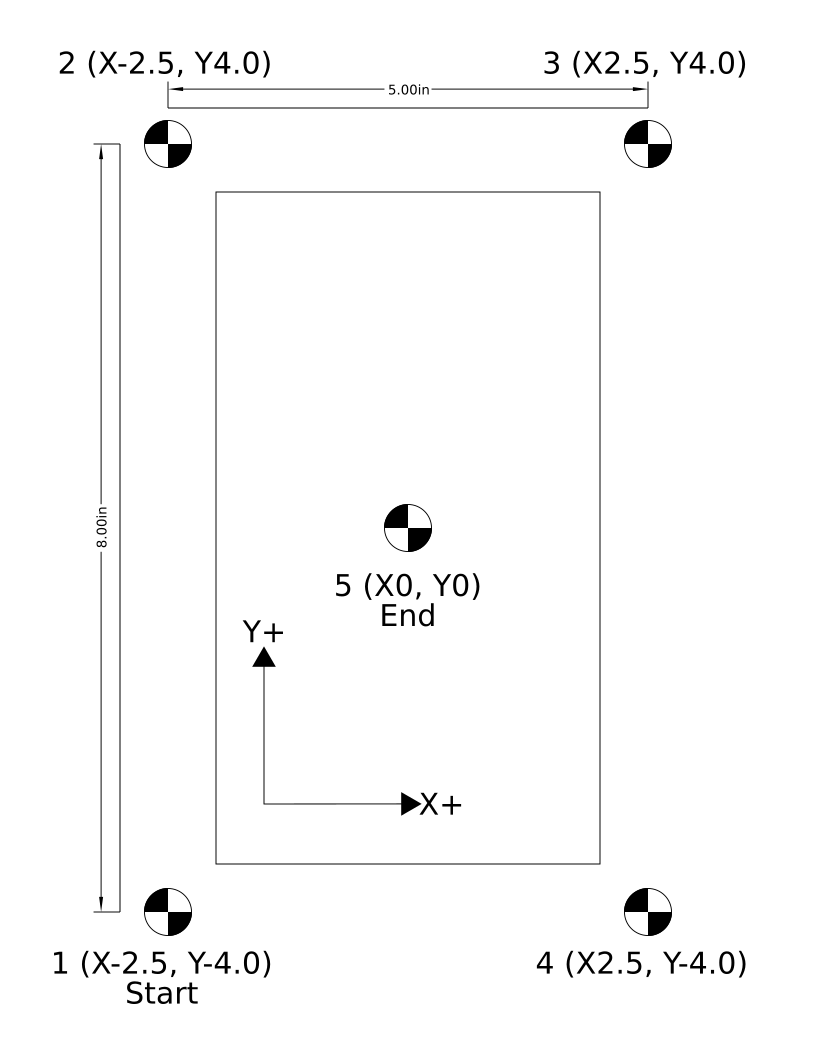
The MachMotion Vision Calibration Sheet is a printed US-Letter-portrait sheet with five black-and-white target marks arranged on a 5.00″ × 8.00″ rectangle plus a center mark. It is the reference geometry used by M283 C1 to solve the full 2×2 K matrix and write the camera-vs-spindle tool offset.
Sheet Layout
| Dot | Position (in) | Notes |
| 1 — Start | (-2.5, -4.0) | Lower-left. Operator parks the camera over this dot before issuing M283 C1. |
| 2 | (-2.5, +4.0) | Upper-left. |
| 3 | (+2.5, +4.0) | Upper-right. |
| 4 | (+2.5, -4.0) | Lower-right. |
| 5 — End | (0, 0) | Sheet center. Used to write the camera tool's X/Y offset and to verify the residual at the end of the cal walk. |
- Outer rectangle: 5.00″ wide (X) × 8.00″ tall (Y), centered on dot 5.
- Mark style: 0.5″ diameter quartered black/white target (high-contrast, symmetric — works well with the Keyence circle / blob detector).
- Walk order: 1 (Start) → 2 → 3 → 4 → 5 (End / Center).
- Trusted axis: X (8.5″ page width prints more accurately than the 11″ page length on most consumer printers).
Printing
- Print the supplied PDF on US Letter (8.5″ × 11″) at 100% scale / Actual Size. Do not use "Fit to Page" or "Shrink to Fit" — the cal math depends on the printed dimensions matching the table above.
- After printing, measure the X distance between dot 1 and dot 4 (or dot 2 and dot 3) with a ruler or caliper. It should read 5.00″ ± 0.01″. If your printer is off by more, scale-correct the PDF before reprinting.
- Use clean, matte paper. Glossy finishes can produce specular reflections that confuse the camera.
Mounting on the Machine
- Tape the sheet flat on the table or fixture. Any wrinkles, bubbles, or curls translate directly into apparent dot-position error.
- Orient the sheet so its X+ arrow points in the same direction as machine X+ and its Y+ arrow points the same direction as machine Y+. Small rotation is fine — the cal routine recovers it — but the sheet's X+ should not be pointing at machine Y+.
- Pick a working area where the spindle and camera both reach all five dots without colliding with fixturing.
A wavy or wrinkled sheet is the single biggest source of calibration error. Tape down all four corners and at least the center of each long edge. Heavier card-stock prints are noticeably better than 20-lb copy paper.
Calibration Procedure
- Mount the sheet as described above.
- Anchor the sheet to the spindle. Activate the spindle tool. Jog so the spindle tip is centered over dot 5 (the middle mark). Zero work-coord X and Y. The cal routine assumes the active WCS reads (0, 0) at dot 5 with the spindle.
- Tool-change to the camera. Issue
Tn M6for the camera tool number (matchesVisionCameraToolNumber). The camera will land somewhere offset from dot 5 because the tool-table X/Y offsets are not calibrated yet — that is normal. - Park over the start dot. Jog the camera in X/Y until dot 1 (lower-left, X-2.5 Y-4.0) is visible in the FOV. Centering is not required; the cal routine accepts any offset that keeps the dot in frame and that survives a 0.1″ bump in X and Y for the axis-detect step.
- Run the cal. Issue
M283 C1. The routine:- Auto-detects camera axis orientation (bumps +0.1″ X then +0.1″ Y, writes
VisionCameraSwapXY/InvertX/InvertY). - Walks dots 1 → 2 → 3 → 4 capturing pixel offset and machine position at each.
- Solves the rigid Procrustes fit and the per-axis K scale.
- Writes K to
VisionCal_K11..K22. - Moves to dot 5 (sheet center) and writes the camera tool's X/Y offsets so the camera lands on (0, 0) when commanded there.
- Re-walks all 5 dots in absolute G90 to report verify residuals.
- Auto-detects camera axis orientation (bumps +0.1″ X then +0.1″ Y, writes
- Inspect the result popup. Look for:
- Scale X ≈ Scale Y — should be within ~1% (e.g. 0.00203 / 0.00203). Wildly different values mean the sheet is rotated 90°, the camera is mounted askew, or the print scale is bad.
- Sheet rotation — small (< 1°). Larger means the sheet was taped down rotated, which is OK as long as it is consistent and small.
- Verify RMS — typically ≤ 0.020″ on a printed sheet. Higher means the sheet is wavy, the lens is dirty, or the lighting is changing during the walk.
Example Cal G-Code
( Vision K-matrix calibration - cal sheet 1 )
( Spindle tool active, X/Y already zeroed over sheet center, )
( camera tool then activated and jogged over dot 1.          )

G90 G20 G17       ( absolute, inches, XY plane )
G54
T98 M6            ( camera tool - change number to match your setup )

M283 C1           ( walk sheet 1, solve K, write camera tool offset )

M30
Verifying the Calibration
After M283 C1 finishes, the camera tool's X/Y tool-table offset should put the camera over the commanded XY. Run the verify program in Example 2 to walk all five dots in absolute G90 with M280 / M281 / M282 active — the residual at the center capture should be < 0.005″ on a flat, well-printed sheet.
Re-run M283 C1 any time the camera is removed and remounted, the lens is touched, the working distance changes (different fixture height), or the verify residual drifts beyond your tolerance.
Camera Z Height & Working Distance
Why Z Height Matters
A smart camera does not measure distance — it measures pixels. The number of pixels per inch (or per mm) is set by the lens focal length and the working distance from the lens to the surface being imaged. The K matrix calibrated by M283 bakes that pixels-per-unit relationship in at the working distance present at calibration time. Move the camera closer or farther from the work surface and every pixel now represents a different real-world distance, so every M281 capture will report the wrong offset.
The Z distance from the camera lens to the top of the material being inspected MUST match the Z distance that was present when M283 C1 was run. Any change in standoff — thicker stock, different fixture, raised/lowered camera bracket, refocused lens — invalidates the calibration and requires a re-cal.
How Much Does It Matter?
For a typical machine-vision lens at a working distance WD, the pixel-to-unit scale changes roughly linearly with WD. A 10% change in standoff produces a ~10% change in measured offsets — on a 1.000″ commanded distance, that is a 0.100″ error. Even a 1% standoff change (about 0.060″ on a typical 6″ working distance) produces a 0.010″ scale error, which is enough to put the verify residual out of spec.
Best Practices
- Rigid camera mount. The camera bracket must not deflect. A loose or springy mount lets vibration change the working distance and degrades repeatability.
- Calibrate at the same Z you will inspect at. If the camera is on the spindle and is moved up/down with the Z axis, calibrate with the camera tool's Z offset and material thickness configured the way they will be at runtime. The cal sheet must be at the same height as the part top.
- Match material thickness. If your production stock is 0.250″ thick, the cal sheet should sit on a 0.250″ spacer (or directly on the part fixture) so its top surface is at the same Z as the parts you will inspect.
- Don't refocus after calibrating. Twisting the lens focus ring changes the optical magnification and silently invalidates K. If you must refocus, re-run
M283 C1immediately after. - Lock down the lens. Most VS-series lenses have a focus lock screw — tighten it after focusing.
- Fixed-Z cameras are easiest. A camera mounted to the gantry or a column at a fixed Z (not the spindle) keeps standoff constant for all parts of a given thickness and is the most robust setup.
When to Re-Calibrate
Re-run M283 C1 whenever any of the following change:
- The camera bracket is loosened, removed, or shimmed.
- The lens is rotated, refocused, swapped, or replaced.
- The aperture is opened/closed enough to noticeably change depth of field.
- Material thickness changes by more than ~5% of the working distance.
- The camera tool's Z offset is changed.
- A different fixture, sub-plate, or vise raises/lowers the part top.
- The verify-walk residual at the center dot starts drifting beyond your tolerance.
Symptom of a wrong Z: calibration converges with a small RMS residual but the production verify dot reports an offset that scales with distance from the work zero (e.g. small error near origin, large error at the far corners). That is a pure scale error and almost always means the working distance changed between cal and run.
M283 — Calibrate K Matrix
Overview
Calibrates the pixel-to-machine-units transform (the K matrix) and the camera-vs-spindle tool offsets. Two modes — exactly one of Q or C must be provided.
Both modes start by running an automatic axis-orientation check: the machine bumps +0.1 in X then +0.1 in Y, captures the resulting raw pixel deltas, and writes VisionCameraSwapXY / VisionCameraInvertX / VisionCameraInvertY so that subsequent triggers report machine-frame pixels. A mark must be in the FOV at the start, and the mark must remain in the FOV after a 0.1-unit bump in X and Y.
Parameters
| Letter | Description |
| Q | Quick diameter calibration. Qd sets K = diag(d/width_px, d/height_px) using a single trigger over a printed dot of known physical diameter d. No motion (besides the axis-detect bump). Useful for first setup or quick checks — assumes the camera is roughly axis-aligned, no off-diagonal terms. |
| C | Cal-sheet walk. Cn selects sheet id n from VisionModule.CAL_SHEETS. The routine commands incremental moves between dots on the printed sheet, captures pixel offset at each, and solves the full 2x2 K by least-squares plus a rigid Procrustes fit. Also writes the camera tool's X/Y tool-table offsets so the camera can be commanded directly in work coords. Recommended. |
M283 Q — Quick Diameter Calibration
- Activate the camera tool (
Tn M6). - Jog the camera so a printed dot is roughly centered in the FOV.
- Issue
M283 Qd, where d is the dot's physical diameter (in current units). - The routine runs the axis-detect bump, triggers the camera, computes K from the reported width/height, and re-triggers to confirm the residual.
( Quick cal: dot in FOV, half-inch printed diameter )
T98 M6
M283 Q0.5
M283 C — Cal-Sheet Walk (Recommended)
- Tape the printed cal sheet flat on the table, oriented as printed (X+ right, Y+ up).
- Activate the SPINDLE tool. Jog over the sheet center (dot 5) and zero work-coord X and Y. This anchors the sheet origin to the spindle.
- Activate the CAMERA tool (
Tn M6). Jog so the camera FOV is over the start dot (dot 1, lower-left). The dot must be visible in frame — perfect centering is not required. - Issue
M283 C1for sheet 1 (US Letter portrait, ±2.5 x ±4.0 in).
On success, a popup reports the per-axis scale, rotation, K matrix, sheet rotation, RMS residual, the tool-offset shift written to the camera tool, and the verify-walk residuals at each dot.
( Cal sheet walk - sheet center is current XY zero, camera tool active )
T98 M6
M283 C1
M284 — Select Camera Job
Overview
Switches the camera to a different program/job. Capability-gated — drivers that do not advertise select_job raise a clean error.
Parameters
| Letter | Description |
| P | Job id to switch to. If omitted (or P0), the persistent OEM VisionActiveJob is applied. On success, VisionActiveJob is updated. |
Examples
M284 P3 ( switch to camera job 3 and remember it )M284 ( apply VisionActiveJob )Example G-Code Programs
Example 1 — Calibration (cal-sheet walk)
( Vision K-matrix calibration - cal sheet 1 )
( 1. Tape sheet flat, X+ right / Y+ up                                  )
( 2. Spindle tool active, jog over sheet CENTER, zero X and Y           )
( 3. Camera tool active, jog over START dot (lower-left -2.5,-4.0)      )

G90 G20 G17       ( absolute, inches, XY plane )
G54
T98 M6            ( camera tool - change number to match your setup )

M283 C1           ( walk sheet 1, solve K, write camera tool offset )

M30
Example 2 — Verify Calibration (5-dot walk in absolute G90)
( Vision alignment test - walks the 5-dot calibration sheet pattern )
( Sheet center = 0,0 in current work coords                         )
( Corners at (+/- 2.5, +/- 4.0) inch                                )
( Walk order: 1 -> 2 -> 3 -> 4 (4-point fit) -> 5 (center verify)   )

G90 G20 G17       ( absolute, inches, XY plane )
G54               ( use whatever WCS is zeroed at sheet center )
T98 M6            ( camera tool )

M280              ( begin 4-point alignment run )

G0 X-2.5 Y-4.0    ( dot 1 - lower left  )
M281

G0 X-2.5 Y4.0     ( dot 2 - upper left  )
M281

G0 X2.5 Y4.0      ( dot 3 - upper right )
M281

G0 X2.5 Y-4.0     ( dot 4 - lower right )
M281

M282              ( solve + apply modal G51 / G68 / G52 )

G0 X0 Y0          ( dot 5 - center, post-fit verify )
M281              ( capture; pound vars #500..#507 show residual )

( Inspect #500 (X), #501 (Y) - both should be ~0 if fit is good. )
( To clear the transform when done:                              )
( G69 G50 G52 X0 Y0                                              )

M30
Example 3 — Quick Diameter Cal
( Quick K calibration from a single dot of known diameter )
( Dot must be in the FOV when M283 Q runs.                 )

G90 G20
T98 M6
M283 Q0.5         ( half-inch printed dot )

M30
Example 4 — 4-Point Rectangle Fit on a Production Part
( Locate a 6 x 4 in part by its 4 corner fiducials, then run the cut )
( Operator drops the part on the fixture roughly square; fiducials   )
( are at the nominal corners (0,0), (6,0), (6,4), (0,4).             )

G90 G20 G17
G54
T98 M6                   ( camera tool )

M280                     ( default 4-point rectangle fit )

G0 X0    Y0
M281                     ( fid 1 )

G0 X6.0  Y0
M281                     ( fid 2 )

G0 X6.0  Y4.0
M281                     ( fid 3 )

G0 X0    Y4.0
M281                     ( fid 4 )

M282                     ( solve and apply modal transform )

T1 M6                    ( swap to cutter )
( ...your normal cutting program in part-design coords...        )
( ...G51/G68/G52 modally re-map every move to the actual part... )

( At end of program, cancel the transform: )
G69 G50 G52 X0 Y0
M30
Example 5 — 3-Point Similarity Fit
( Locate a part by 3 fiducials (similarity fit - shift, rotate, uniform scale) )

G90 G20 G17
G54
T98 M6

M280 P3                  ( 3-point similarity fit )

G0 X0    Y0
M281

G0 X8.0  Y0
M281

G0 X4.0  Y6.0
M281

M282                     ( apply )

T1 M6
( ...cutting program... )

G69 G50 G52 X0 Y0
M30
Example 6 — Reading the Result with Pound Variables
( Single-mark inspection: trigger and use the result in G-code math )
( Requires VisionPoundVarBase = 500 (default).                      )

G90 G20
T98 M6
M280                     ( begin run so M281 has somewhere to store the dot )

G0 X10.0 Y8.0
M281                     ( capture; #500=obs X, #501=obs Y, #502=W_px, #503=H_px )

( Apply the deviation as a fixture offset on G55: )
G10 L2 P2 X[#500] Y[#501]

M30
Example 7 — Switching Camera Jobs Mid-Program
( Use a coarse fiducial finder for the rough alignment, then switch  )
( to a precise circle-fit job for the final inspection step.         )

G90 G20
T98 M6

M284 P1                  ( camera job 1 = coarse finder )
M280
G0 X0 Y0
M281
G0 X10.0 Y0
M281
G0 X10.0 Y6.0
M281
G0 X0    Y6.0
M281
M282                     ( apply alignment using job 1 captures )

M284 P2                  ( camera job 2 = precise circle fit )
G0 X5.0 Y3.0
M281                     ( fine-grained measurement at part center, in aligned frame )

G69 G50 G52 X0 Y0
M30
Error Handling and Diagnostics
Error Types
| Symptom | Likely Cause / Fix |
timeout |
Camera unreachable, wrong IP/port, or no Data Output (Non-Procedural) tool configured to emit on TRG. |
connection refused |
Camera not in Run Mode, or another client already holds the socket. |
NG / no mark found |
The configured camera job did not find a fiducial in the FOV. Re-jog over the mark, check lighting, verify the camera job is locating the right feature. |
K matrix is zero -- run M283 to calibrate first |
VisionCal_K11..K22 are all zero. Run M283 C1 (or M283 Q). |
camera tool Tn is not the active tool |
VisionCameraToolNumber is set, but a different tool is active. Issue Tn M6 for the camera tool first, or clear the OEM to disable the check. |
VisionPoundVarBase is in reserved range |
Move the base out of 5061..5081 or 5201..5500; pick a value ≥ 100. |
ER,TRG,01 |
Camera does not accept TRG in its current mode — not in Run Mode. |
ER,TRG,06 |
Command not executable — trigger source is not Communication. |
ER,TRG,07 |
Camera-side measurement timed out within its configured window. |
| Malformed response | The Data Output tool is missing, disabled, or emitting unexpected fields. |
Status Storage
On every trigger, VisionLastStatus is updated — OK on success, otherwise the error text. Surface it as a screen DRO for live diagnostics.
Axis Orientation Mismatch
If the camera is mounted rotated 90° or with one or both axes flipped relative to the machine, every trigger reports pixels in the wrong frame and downstream cal / fit residuals will be large or non-converging. Symptoms include a residual that grows with the bump distance instead of shrinking, or a sheet-rotation result around 90°.
Run M283 C1 (or M283 Q) with a mark in the FOV. The pre-flight axis-detect bump test automatically writes the correct values for VisionCameraSwapXY, VisionCameraInvertX, and VisionCameraInvertY.
Protocol Reference (Keyence Driver)
The Keyence driver implements a minimal subset of the VS Non-Procedural protocol. See the Keyence VS series user manual for the full command set.
| Command | Description |
TRG |
Trigger a single measurement. Camera echoes TRG\r and emits the configured Data Output line(s). |
FVR |
Firmware version read. Used by the GUI Test Connection button. |
PR / PW |
Program (job) read / write. Used by M284 when the driver advertises select_job. |
- Each command is terminated with
CR(0x0D). - Maximum command size: 500 bytes.
- Camera-side per-command timeout: 3 seconds.
- Error responses follow
ER,<cmd>,<nn>\r, wherennis a two-digit error code (01 unknown, 02 args, 03 range, 04 type, 05 not acceptable, 06 not executable, 07 timeout).
Camera vs. Tool Position
The camera reports an offset relative to its own optical center, not to the spindle or working tool. The cal-sheet walk (M283 C) handles this correctly by writing the camera-vs-spindle offset directly into the camera's tool-table entry. After cal, with the camera tool active, a commanded XY positions the camera at that XY. After tool-changing back to the cutter, the same XY positions the cutter at that XY — the alignment transform from M282 applies to both.
Appendix A — OEM Parameter Reference
Every OEM parameter the Vision system reads or writes, grouped by section as it appears in the Configuration → Vision screen. Parameters in the Last Result and Run State sections are runtime telemetry — they are written by the module on every capture / fit and are not intended to be edited by the operator. All names are prefixed with Vision and stored in the profile-level OEM database.
Connection
| Name | Type | Default | Description |
VisionEnabled |
yesno | No | Master enable. When No, every Vision M-code returns a clean "Vision is not enabled" error and no driver is loaded. |
VisionDriver |
choice | Keyence | Driver selector. Currently only the Keyence VS-series driver is shipped; new cameras are added by writing additional drivers under Modules/Addons/Vision/Drivers. |
VisionIP |
text | 192.168.208.80 | Camera IP address. The PC and the camera must be on the same subnet. |
VisionPort |
integer | 8500 | TCP port for the camera's data-output channel. Keyence VS default is 8500. |
VisionTimeout |
integer (s) | 3 | Per-command socket I/O timeout. Increase only if the network is unreliable; longer timeouts mask real failures. |
VisionActiveJob |
integer | 0 | Persistent "current job" selector. Updated by M284 Pn. M284 with no argument re-applies whatever value is stored here. |
VisionImageWatchDir |
text | (empty) | Local folder the camera FTP-pushes inspection images to. Used by M281 D1 to grab and rename the most recent image. |
VisionImageGrabTimeout |
float (s) | 2.0 | How long M281 D1 waits for a new image to appear in the watch folder before giving up. |
VisionCameraResX |
integer (px) | 1776 | Camera image width in pixels. Used to convert from native top-left pixel coords to signed image-center offsets. |
VisionCameraResY |
integer (px) | 1776 | Camera image height in pixels. Same role as VisionCameraResX on the Y axis. |
VisionTriggerSettleSec |
float (s) | 0.25 | Dwell M283 inserts after each commanded move and before triggering the camera. Lets motion settle so the captured pixel reading is stable. Production captures (M281) do not auto-dwell — precede them with a programmed G4 P if needed. |
VisionCameraSwapXY |
yesno | No | Camera-to-machine axis remap: swap raw pixel X and Y. Auto-set by the M283 axis-detect pre-flight bump. |
VisionCameraInvertX |
yesno | No | Camera-to-machine axis remap: negate raw pixel X (after any swap). Auto-set by M283. |
VisionCameraInvertY |
yesno | No | Camera-to-machine axis remap: negate raw pixel Y (after any swap). Auto-set by M283. |
Calibration
| Name | Type | Default | Description |
VisionCal_K11 |
float | 0 | Row 1, column 1 of the 2×2 K matrix. Pixels → machine-units in the X direction (plus any small camera/machine rotation cross-term goes into K12). |
VisionCal_K12 |
float | 0 | Row 1, column 2 of K. Captures small Y-pixel-into-X-units cross-coupling from camera/machine rotation. |
VisionCal_K21 |
float | 0 | Row 2, column 1 of K. Captures X-pixel-into-Y-units cross-coupling. |
VisionCal_K22 |
float | 0 | Row 2, column 2 of K. Pixels → machine-units in the Y direction. |
VisionCal_Date |
text (ISO) | (empty) | Local-time ISO timestamp written by M283 on a successful calibration. Useful as a screen DRO so an operator can see when the camera was last calibrated. |
VisionCal_Units |
choice | in | Units the K matrix was calibrated in (in or mm). The Vision module checks this against the current G20/G21 mode at trigger time. |
VisionPxCenterOffsetX |
float (px) | 0 | Optional bias added to the centered pixel X before applying K. Lets you correct for a camera whose optical center is not exactly the image-array center. |
VisionPxCenterOffsetY |
float (px) | 0 | Same as VisionPxCenterOffsetX, on the Y axis. |
Do not edit VisionCal_K11..K22 by hand. They are written atomically by M283; partial edits leave the camera mis-calibrated. Re-run M283 C1 instead.
Output
| Name | Type | Default | Description |
VisionPoundVarBase |
integer | 500 | Base pound-variable index for M281 output. Slot 0 sits at base, the photo count at base+8, and the four indexed point slots at base+20..base+51 (see Pound-Variable Output). M280 clears base..base+51 to the value of pound var #0. Must be ≥ 100 and outside the reserved Mach ranges 5061..5081 and 5201..5500. |
VisionCameraToolNumber |
integer | 0 | Camera tool number used in the tool table. M280 / M281 / M282 / M283 verify this tool is the active spindle tool and abort otherwise. Set to 0 to disable the check (not recommended for production). |
Last Result (telemetry — read-only)
| Name | Units | Description |
VisionLastJudgment |
1=OK / 0=NG | Pass/fail flag from the most recent camera trigger. |
VisionLastOffsetPxX |
px | Raw centered pixel offset X reported by the driver, after image-center shift but before swap/invert and K. |
VisionLastOffsetPxY |
px | Raw centered pixel offset Y, same conventions as VisionLastOffsetPxX. |
VisionLastOffsetX |
units | Pixel offset converted to machine units via the K matrix. This is the value M281 stores in pound var #base+0. |
VisionLastOffsetY |
units | Pixel offset converted to machine units, Y axis. |
VisionLastWidth |
units | Detected feature width from the camera (pixels × X-axis K column norm), in current machine units. |
VisionLastHeight |
units | Detected feature height (pixels × Y-axis K column norm), in current machine units. |
VisionLastAngle |
deg | Detected feature angle, if the camera job emits it. |
VisionLastScore |
— | Camera-side match score (driver-specific). Clamped to a minimum of 1 for any successful capture. Useful as a quality gate. |
VisionLastStatus |
text | OK on success, otherwise the error string. Surface as a screen DRO for live diagnostics. |
Run State (telemetry — read-only)
| Name | Units | Description |
VisionRun_Active |
0/1 | 1 between M280 and M282; 0 otherwise. |
VisionRun_Mode |
4 / 3 | 4 = rectangle (4-point) fit, 3 = similarity (3-point) fit. Set by M280 P. |
VisionRun_DotCount |
integer | How many M281 captures have been collected so far. |
VisionRun_Tx / VisionRun_Ty |
units | Solved shift, emitted as G52. |
VisionRun_Theta |
radians | Solved rotation, emitted as G68 R (converted to degrees on output). |
VisionRun_Sx / VisionRun_Sy |
scale | Solved per-axis scale (rectangle fit only), emitted as G51 X Y. |
VisionRun_CenterX / VisionRun_CenterY |
units | Rotation/scale center, emitted as G68 X Y / G51. |
Appendix B — Pixel-to-Machine-Units Math
This appendix walks the full transform chain a single capture goes through, from the camera's wire-format pixel reading to the observed point that M281 stores. Every step is implemented in VisionModule.lua / VisionMath.lua; the field references in parentheses point at the OEM parameters that drive each step.
Step 1 — Camera Native Pixels
The Keyence VS-series camera reports a hit as two floating-point pixel values: (px_native_x, px_native_y). The native frame is camera-defined — for the VS series, origin is the top-left of the image, X grows to the right, Y grows downward. Image dimensions are VisionCameraResX × VisionCameraResY pixels. The driver hands these values to the module unchanged.
Step 2 — Image-Center Shift
VisionModule.CenterRawPixels() converts the top-left-origin native pixel to a signed offset from the image center, and optionally applies a per-camera optical-center bias (VisionPxCenterOffsetX, VisionPxCenterOffsetY):
px_centered_x = px_native_x - (VisionCameraResX / 2) - VisionPxCenterOffsetX
px_centered_y = px_native_y - (VisionCameraResY / 2) - VisionPxCenterOffsetY
After this step, (0, 0) means the feature is exactly under the optical axis. The PxCenterOffset terms are normally zero — only set them if you have evidence the camera's optical center is biased away from the array center.
Step 3 — Camera-to-Machine Axis Remap
The camera can be physically mounted rotated 90° or with one axis flipped relative to the machine. The three boolean OEMs VisionCameraSwapXY, VisionCameraInvertX, VisionCameraInvertY normalize the centered pixel into the machine frame. They are applied in this order:
if VisionCameraSwapXY then
    swap(px_centered_x, px_centered_y)
end
if VisionCameraInvertX then px_centered_x = -px_centered_x end
if VisionCameraInvertY then px_centered_y = -px_centered_y end
After this step, "positive pixel X" means the same direction as "positive machine X." M283's pre-flight bump test (a small +X then +Y move) sets these three flags automatically by checking which raw pixel axis moved and which sign.
Step 4 — K Matrix (Pixels → Machine Units)
VisionMath.ApplyK() applies the calibrated 2×2 K matrix to convert from machine-frame pixels to machine units (inches or millimeters, per VisionCal_Units):
| dx_units |   | K11  K12 |   | px_centered_x |
|          | = |          | * |               |
| dy_units |   | K21  K22 |   | px_centered_y |
In an ideal install where the camera is square to the machine and the same scale on both axes, K = diag(s, s) where s is units-per-pixel. The off-diagonal terms K12 and K21 capture residual rotation between the camera array and the machine that the Step 3 boolean remap can't represent (because rotation is continuous, not 90°-discrete). They are normally small but nonzero after a real M283 C1 walk.
dx_units / dy_units is the offset from the optical axis to the detected feature, expressed in current G-code units. It is not a machine coordinate — it is a delta. Step 5 converts the delta into an absolute observed point.
Step 5 — Observed Point in Machine Coordinates
At the moment of the trigger, VisionModule reads the commanded XY from mc.mcAxisGetPos for the active WCS and adds the units-frame delta to get the observed point of the feature:
observed_x = commanded_x + dx_units
observed_y = commanded_y + dy_units
This is the value M281 stores into pound vars #base+0 / #base+1 and into the dot list used by M282. The fit step (M282) compares this observed point against the commanded point that was active when the trigger fired and solves a rigid-body transform from the commanded grid to the observed grid.
Full Transform — One Equation
Combining Steps 1–5, the observed point as a function of the camera's wire-format reading is:
observed = commanded + K * R * (px_native - res/2 - PxCenterOffset)where R is the discrete ±1 / swap remap from Step 3, K is the continuous 2×2 calibration matrix from Step 4, and res/2 is the image-center vector. The cal-sheet walk in M283 C solves for both R (axis-detect bump) and K (Procrustes fit over the dot grid).
Where Each Step Lives in Code
| Step | Function | File |
| 1. Native px | KeyenceVisionDriver:Trigger() |
Modules/Addons/Vision/Drivers/KeyenceVisionDriver.lua |
| 2. Center shift | VisionModule.CenterRawPixels() |
Modules/Addons/Vision/VisionModule.lua |
| 3. Swap / invert | VisionModule.RemapToMachineFrame() |
Modules/Addons/Vision/VisionModule.lua |
| 4. K matrix | VisionMath.ApplyK() |
Modules/Addons/Vision/VisionMath.lua |
| 5. Observed point | VisionModule.PxToMachine() + _m281 |
VisionModule.lua / CommonMCodeModule.lua |