Using PMC to Setup Safety Interlock
"PMC" (or Programmable Motion Controller) is a Mach feature that uses ladder logic programming to do more complicated I/O configuration. While it has many applications, we most commonly use it to create a safety interlock that states certain criteria must be met before an output can be turned on.
First, a quick explanation of "ladder logic."
https://www.youtube.com/watch?v=A07ONVjqGfY
So, lets say you have a standard knee mill that has a tool"Tool releaseRelease" button configured to input #2#2. and thatThen, you would like to configure that button to fireturn on output #2, a drawbar solenoid that would release thea tool onfrom outputthe #2.spindle. Sounds easy enough, right? Why would't you just do this in GMS?
The PMC has extra flexibility to add other conditions to the process! Because, as you can imagine, you would never want the drawbar to release WHILE THE SPINDLE IS RUNNING! This would throw the tool out and could damage something or someone.
So, your PMC adds more conditions to this I/O process. So... IF Mach is in an idle state, IF the spindle RPM is at zero, IF the input #2 input is high...
THEN set out #2 to high!
Note: The PMC files that come on a standard Mach install are in the C:\Mach4\Pmc folder on the machine hard drive. The exist both as a PMC file that you can edit and as a .lua script that Mach can run.
Setting up A Safety Interlock Using the "Router" PMC
1) Turn on the PMC
- To turn on the PMC, first go to "Operator->Edit Screen" on the main menu.
- Then at the top left of the screen in the "Screen Tree Manager" click on the machine type. (
PicturedFigurebelow.)1) - At the bottom of the tree manager, click the "..." box under "PMC Oblects." (
PicturedFigurebelow.)The1) Then, put a check next to "Router" and click "OK." - Click "Operator->Edit Screen" again. Click "Yes" when prompted to save the screen.


(Figure 1)
2) Understanding the PMC and Ladder Logic
While this is not an exhaustive list, it iswill hopefullygive you a usefulquick reference that willto help you think through the ladder logic before moving on to configuration. Use the image below as a reference.guide.
- First, to open the
PMC,PMC on a machine, go to "Configure->PMC" on the main menu. - Then click "File->Open" and select "Router.pmc" to see the configuration for the PMC. (
PicturedFigure 2 below is the factory settings for the Router PMC we ship with a standard 2050 Knee Mill.) - Ladder logic gets read top to bottom, left to right. So, when reading this, you would start at the top right, following sequence 1 through 13
as notedshown in pink in Figure 2. - Please not that everything here is configurable. If you double click on any rungs on the
photoladder,below.it will bring up a screen where you can configure the parameters. - You will see several brackets on the rungs; shown as "] [" or "]/[." These brackets are simply showing the signal condition. Just think
thatof it this way...- ] [ means "Yes" and ]/[ means "
No."No" - So, for example, on #5 in the
sequence,sequence on Figure 2, the "FSpindleOn" condition is "]/[" meaning "no;" we do not want the spindle on!
- ] [ means "Yes" and ]/[ means "
- You will see several numbers set throughout the PMC. These are looking for specific states or values to be true. For example, if look at sequence #3 in the ladder
logic,logic on Figure 2, you'll see several different different numbers belowit.itTheselookingnumbers notatefor different "states" Mach should be in.- "
states.0" is Mach in an "idle"Whilestate. - So, "0" is "AMachState" that must be true (=) to move though the ladder.
- And remember, there are many
Mach states, these three will be a part of the process we are setting up; "0" ismore Machat"states!"idle(108,and207,mustetc.)
beone of the conditions met moving down the ladder. - "
- The "R" and "S" values in the ladder stand for "Reset" and "Set." These are at the end of the ladder on Figure 2. That is because they are used for the signal we are using the PMC to
program.program!So,Just think of it this way...- "Set" is turn on
and--- "Reset" is turnoff.off - Let's
ifthinkyouthroughlookthe example below. Look at "FReleaseTool"below,signalifatthe
the end of the ladder- If the "GToolReleaseBtn" button condition is "] [" (or "
yes,"yes"), it puts "sets"FReleaseTool" to "S" (or "turns on"). - If the "GToolReleaseBtn" button condition is "]/[" (or "
no,"no"), it puts "resets"FReleaseTool" to "R" (or "turns off").
the release tool.therelease - If the "GToolReleaseBtn" button condition is "] [" (or "
So,tool. - "Set" is turn on
- "OSR" (shown at #9 and #12 in Figure 2) stands for "One Shot Rising" and is used to configure one time events in a PLC/PMC. These are not typically used for this type of safety interlock.

3) Programming the PMC for a Tool Release Safety Interlock
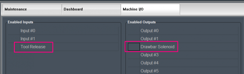
Let's return to our example from section 1; tool release button in input #2 and drawbar solenoid in output #2.
- Select "Configure->PMC" from the main menu.
- Then click "File->Open" and select "Router.pmc" to see the configuration for this PMC.
- Delete both "OSR" items clicking them and hitting "Delete" on your keyboard.
- Double click on "GToolReleaseBtn ] [." Change to the desired source, input and rename.
- Double click on "GToolReleaseBtn ]/[." Change to the desired source, input and rename.
- Double click on "FReleaseTool (S)." Change to the desired source, input and rename.
- Double click on "FReleaseTool (R)." Change to the desired source, input and rename.
- Click "File->Save" to save the new PMC config.
- Close the PMC window.
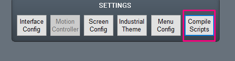
- Navigate to the "Service" tab in Mach. Then navigate to the "maintenance" tab.
- Hit "Compile Scripts" to save the new PMC to a .lue file that Mach can use.