Lathe Tool Tip Types
Turn Tip Types
The tip type (usually represented by a number) expresses the direction and useful paths of travel that a particular tool can cut. Most tips are "pointed" in a particular direction and have a limited angle at which they can cut. (There are no practical omnidirectional cutting tools on a lathe.) The tool tip type indicates which axis/axes you can cut along. The tip type also determines how tool nose compensation is applied.
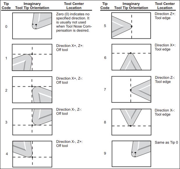
In the following diagram, each tool type is shown, with the direction of X and Z where the tool is "pointing" and the cutting direction(s) indicated by the dotted lines.
(Image Source: University of Florida, Mechanical & Aerospace Engineering)
In this diagram, +Z is to the right, and +X is up (the same as in the previous diagram).
(Image Source: CNC Programming Handbook, 3rd Ed.; Peter Smid; p276)
These diagrams are for a rear-turret lathe. Some diagrams you may find will look (vertically) reversed because they are describing orientations for a front-turret lathe.
Turn Operations and Tip Types
Machinists will frequently associate tip types with types of turning.
-
Turning
- cutting surface is in the -X direction
- tip types: 2, 6, 1
-
Boring
- cutting surface is in the +X direction (i.e. hollowing out the inside of something)
- tip types: 3, 8, 4
-
Facing
- cutting surface is in the -Z direction (i.e. removing material from the end, or "face," of the work piece)
- tip types: 2, 7, 3
-
Back Facing
- cutting surface is in the +Z direction (i.e. removing material from an "inside face" of a part)
- tip types: 1, 5, 4
Resources
- Tool Probing / Zeroing (mae.ufl.edu)
- Lathe Tool Orientation (linuxcnc.org)
- Tool Nose Radius Compensation (cncprogramming.blogspot.com)
- Cutter Radius Compensation (infosys.beckhoff.com)
- Tool Nose Radius Offset (pp. 275-278; CNC Programming Handbook, 3rd Ed., Peter Smid)
- Machine Type Operations (llbc.edu)