Alexsys V4 Mill Operator Manual
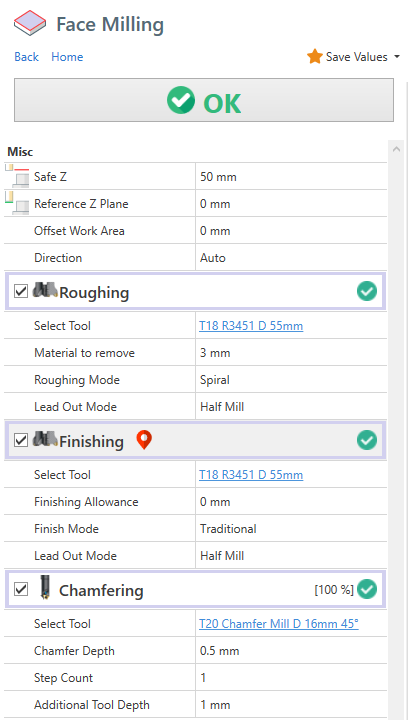
Face Milling
Safe Z : It's the z coordinate where the tool is safe , where it can't collide with anything ( fixture , stock , ..)
Reference Z Plane : Is the reference z coordinate. Usually it's the zero part Z0
Parallel strategy ( traditional ) :
Direction Auto : The direction is calculated automatically
Direction Horizontal : The direction is parallel to X axis
Direction Vertical : The direction is parallel to Y axis
Child operations available
1) Roughing
It process multiple passes in z direction to remove all the material to remove.
The passes depth is determined by the tool cutting data parameter. ( Max Cut Height )
Material to remove : Measured from Reference Z Plane to Z+ direction
Roughing Mode : It's the selected strategy
2) Finishing
It perform the last finish pass on the part face.
Finishing allowance : It's the material left by the roughing operation
3) Chamfering
Contour and Pocket operations
This 2 machining operations are identical except the fact , by default , contour will work the outer area of selected profiles, and pocket will work the inner area of selected profiles.

Switch profile side
Is possible switch the side of selected geometry.
You can both click on the double sided arrow in geometry list box or click the yellow arrow in viewport . When you hover the yellow arrow with mouse cursor , the arrow will turn red. Click on it to change working side.
The highlighted area in viewport , will be the area machined away by the operation.


Open Profiles
Contour and Pocket operations need a closed profile to work with.
If you select an open profile instead, Alexsys will try to close it with the outer stock profile.
See image.
Also in this case you can switch working side .
Z Levels
Safe Z : is the Z Plane where the tool approach in rapid movement
Start Z : Is the z plane where the tool start remove material
Depth : Is the thickness of material to be removed , measuered from Start Z
By default these values are applied to all associated geometries.
But if you enable the " DEFINE Z LEVELS FOR GEOMETRY" , these value are applied only to current geometry. The current geometry is highlighted with red strokes in viewport and active in geometry list box

Groove Width
With a 0 value in WIDTH property , the region area is filled .Like this

But if i set a value in WIDTH the working area is created by offseting the source profile , like this.

This property is set just to the selected profile in geometry list box.
Overhang
Overhange feature is useful to create the side slots with this tool.

You need to enable [Is Overhang Active] and set the [Slot Height]
The bottom part of the slot is determined by the [Start Z] and [Depth] values. The Slot height is measured from the bottom part to Z+ direction.

By default , the outer overhang area is defined by the stock outer contourn.
Roughing plunge points
To force plunge point position for roughing operation, enable "Select Plunge Point" to pick to position with mouse.
Use [Clear Points Selection] to remove all defined plunge points.
Finishing Start Points
Is also possible define finishing start points. Use [Define starting points] under finishing operation.

Use [Clear Points Selection] to remove all defined plunge points.
Keep Tool Down
By default, after every pass in Z direction, the tool move to [Safe Z] level . The reason is to keep the maximum safety in toolpath creation.
But if you see there is no issue with stock collision, you can enable [Keep Tool Down] . In this way the tool goes directly to next z level , without moving to [Safe Z] after every pass.
You have 2 different [Keep Tool Down] options, one under roughing operation and one under finishing operation. So you can have active in one operation and disabled in the other.

Finishing Offset
Is possible apply a negative or positive offset value to profile. With this you can remove more or less material from stock with finishing tool.

Override Geometries
In this image, only a square is defined in geometry selection box. The stock profile is defined by the stock setup. The toolpath is calculated in order to remove all the material from stock until it reach the defined profile.

Is possible override stock profile by :
- Adding a new entity to geometry selection, in this case a circle
- Setting it as [Stock Profile] from the dropdown menu.


With the new stock profile defined , the toolpath in calculated in order to remove just the material from custom stock profile.

Trim By Stock
Let's say this is your current stock model.

Then you need to machine a squared shape . By default this is the generated toolpath. You cleary notice the tool is working on already machined area. The toolpath is not optimal.
 You can enable [Trim toolpath by current stock] .

The toolpath engine will calculate the stock model resulting from previous operations, and will use that model to skip the already machined area.

This will be the optimized toolpath. Now the tool works only where there are material to remove.

The [Trim By Current Stock] feature is computationally expensive.
Where applicable, use the override geometries method, which is more light to process.
Engraving
With ENGRAVING machining operation is possible to engrave text and geometries.
For text is available :
- Single Line font
- True Type font type , with any font family installed on pc.
You can define text on circular or linear pattern, mirrored around X or Y axis and you can apply many alignement options.
And of course all the selected geometry can be engraved.

Cut Operation
This is the machining you need to use when you want cut 2D Profile from material sheet.
Just select the geometries of the profile you want to cut.
Select the relative position of the tool :
- Internal
- Central
- External


Holding tabs
Holding tabs are needed in order to keep your cutted part stable after the machining.
In this way the machine or tool are not damaged.
You need to manually remove the cutted part from sheet.
Check the property ADD HOLDING TABS.
To create this holding tabs, the tool need to raise in some points.
You have to define the thickness and length of this holding tabs.
To define the position you can proceed manually or use the automatic method.
Automatic Mode
With automatic method, you need to define how many holding tabs you want to add.
The positions are calculated automatically.
Manual Mode
If you want to set the holding tabs in precise point, you need to select [Manual Mode].
Then click on [Pick Point], and click with mouse in desired points.


Thread Milling
IN THIS ARTICLE

Common parameters
Select Tool : You need to choose a thread mill tool. In case of internal thread , is necessary a tool diameter a bit smaller than predrill diameter.
Select Thread Category : Choose the thread family from dropdown field
Threading : Select the thread dimension you need. If you need to add a new row or edit some default data , open thread table and edit related property. To open the thread table you can click on the button at side of this field. Or from menu -> edit -> thread table.
Pitch : It's one of the field that will be defined automatically after choosing thread row. You can edit it manually
External Threading : Check this if you need to create an external threading.
Depth : Thread depth measured from [Start Z] level.
Thread Mode : You can choose between :
- Right Handed - Climb
- Right Handed - Conventional
- Left Handed - Climb
- Left Handed - Conventional
The suggested working method is Climb
Compensation Mode : See related page for more info.
Step Count : For larger thread , it's better create the thread with multiple axial pass.
First Step % : Available when you select for the one pass to create the thread. It indicated the % of material removed from the first pass.
Internal Thread
After selection of thread dimension. All the thread related property are filled with data from thread table.
Diameter : It's the diameter of thread helix. In case of [Computer] or [Tool Wear] compensation . it will be reduced by tool diameter.
Predrill Diameter : It's used as start approach diameter. The tool will reach touch this diameter and then will approach the helix diameter with a arc tangent movement.
External Thread
After selection of thread dimension. All the thread related property are filled with data from thread table.
External Diameter : It's used as start approach diameter. The tool will reach touch this diameter and then will approach the helix diameter with a arc tangent movement.
Inner Diameter: It's the diameter of thread helix. In case of [Computer] or [Tool Wear] compensation . it will be increased by tool diameter.

Multi Teeth Tool
From tool geometry screen , is possible define multiple teeth .
 The generated toolpath will be compensated in order to use all the teeth, resulting in shorter toolpath.
Toolpath created with single tooth tool.

Toolpath created with multiple teeth tool.

Adaptive Toolpath Strategy
It's considered a high efficency because it can easily extend your tool life using a different path compared to the traditional OFFSET strategy.
- The tool never work on full load.
- Tool wear distributed uniformly along the flute
- Less power needed from machine
- It never exceed tool engament angle, in this way on the tool is never "overloaded" with material to remove
- It's not necessary have particular machines to get benefits of this

This is the common default OFFSET toolpath. In indicated point the tool work almost at full cut and there is a big engagement angle.

This one is the toolpath generated with ADAPTIVE strategy . You can see the tool works with constant load and never exceed a high engagement angle. In this way you can use deeper passes in order to distribuite the force all along the flute.

- https://www.harveyperformance.com/in-the-loupe/8-ways-youre-killing-your-end-mill/ , in particulat to section "Using Traditional Roughing"
- https://www.cnccookbook.com/thinking-about-high-speed-machining-corners-stepover/
- https://www.cnccookbook.com/high-speed-machining-trochoidal-milling-hsm-speeds-and-feeds
How to change feed value to link moves ?
From version 4.1.0.111
You can edit the default feed in link moves from post processor dialog.
1) Select the Machine Properties tab
2) Search "adaptive"
3) Insert your custom value. Leave 0 to use the fabric default value.

Chamfering Operation
You can find the chamfering operation in almost all the milling machining.
It's used to create a chamfer on the material with a tapered tool.
Chamfer Depth : It's the dimension of the desidered chamfer
Step Count : Sometimes it's preferable create the chamfer with multiple passes, with this property you decide how passes you need. The tool depths are calculated keeping constant the volume of removed material .
Additional tool depth : This property allow to move the tool down in Z- direction , but keeping the same chamfer depth .
Useful if you want to move the contact point away from tool tip.

Tool Diameter Compensation
In Alexsys there are 3 compensation mode available :
Within CNC Mode and Tool Wear Mode , a linear approach movement is automatically added at start and at the end of toolpath.
This is necessary to enable machine tool compensation.
In the output code are visible codes for enabling / disabling cutter compensation (usually G41/G42/G40).
The linear approach movement is 5% larger than the tool diameter.
Computer Mode
This is the most compatible mode, since the final path is calculated automatically. The output code don't contains any command related to compensation ( usually G41 - G42 )
It's not possible adjust the toolpath from the machine tool table. You don't have to worry about setting tool diameter in Tool Diameter register.
It's not indicate if you have to keep tight tolerances in your workpiece.
See at bottom page for info about output code .
Computer Compensation Mode:

CNC Mode
This the least compatible mode. The output path reflect exaclty the geometry profile. All the offset distance and effective toolpath are calculated by cnc machine.
With this mode is necessary define tool diameter in cnc machine tool table. Is possible adjust tool wear value in order to compensate possible tool deflection.
The toolpath preview and simulation always show the uncompensated path. This issue can be visually misleading to the user.
The toolpath will be compensated in cnc machine, so there you'll get desired toolpath.
CNC Compensation Mode:

Tool Wear Mode
The offset diameter is calculated by the computer, but you can also adjust the toolpath editing the machine tool wear table .
This permits to have less incompatibility issues with cnc.
Tool Wear Compensation Mode:

Both in CNC Compensation and Tool Wear compensation, if toolpath engine can't create proper lead in / lead out movement, an error is raised.

If this happen, try to reduce the approach radius value , under the finishing operation

Output Code
To help the machininst have clear what compensation is enabled and what values has to insert in cnc tool registry, in the output code are visible all this information.
Both in tool summary and when the tool is actually called.
Computer Compensation Example :
In Tool Summary :
(#7 - END MILL D 8MM COMP COMPUTER - RADIUS COR VALUE 0)
On Tool Called :
N5 (POCKET - FINISHING) (COMP COMPUTER - RADIUS CORRECTOR VALUE 0) (END MILL D 8MM)
CNC Compensation Example :
In Tool Summary :
(#7 - END MILL D 8MM COMP NCCONTROL - RADIUS COR VALUE 4)
On Tool Called :
N5 (POCKET - FINISHING) (COMP NCCONTROL - RADIUS CORRECTOR VALUE 4) (END MILL D 8MM)
Tool Wear Example :
In Tool Summary :
(#7 - END MILL D 8MM COMP TOOLWEAR - RADIUS COR VALUE 0)
On Tool Called :
N5 (POCKET - FINISHING) (COMP TOOLWEAR - RADIUS CORRECTOR VALUE 0) (END MILL D 8MM)
In this way , directly from gcode , you can see what compensation mode is going to be activated , and what value have the machinist have to insert in the machine tool table.
From this comments ,you have to set the tool diameter only with CNC Compensation, with the other two modes you have to set to 0 the tool diameter.
Operations Logical Sort
In home treeview toolbar, is visible the Logical operation sort button.

When enabled , all the operation are keep sorted by logical flow of the machining logic.
So , for example, the centering operation comes before the drilling operation, the drilling operation comes before the tapping operation, the roughing operation comes before the finishing operation and so on.
Advanced Profile Selection
With [Chain Selection] is possible select contiguous entities. Entities be defined contiguous when they have a common endpoint.
But sometimes we need to extract profiles from intersectiong geometries. See case below.
In this case , it comes useful another kind of profile selection. To add entities to selection you can :
- Keep pressed [CTRL] and keep pressed [Mouse Left Button] and hover with cursor to ADD to selection group .
- Keep pressed [CTRL] and single Click on entity with [Mouse Left Button] to ADD to selection group .
- Keep pressed [SHIFT] and keep pressed [Mouse Left Button] and hover with cursor to REMOVE from selection group .
- Keep pressed [SHIFT] and Single Click on entity with [Mouse Left Button] to REMOVE from selection group.
- Press [ESC] to reset current selection

