Tool Offset Table Customization
Tool X and Y Offsets
PullOpen downthe View->Tool Table

SelectOpen the Edit->Tool Table Editor
-
In the tool table window, click Edit → Table Fields.
to
SelectAdd the X and Y Offset Fields
-
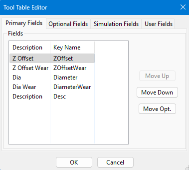
Click the Optional Field
Tab.tab. -
ThenFind the field name XOffset, selectthe key name XOffsetit, andpressclick Move Pri.Repeat -
Do the same for
the YOffset.YOffset. -
PressClick OKandtoyousave. -
You should
havenow see X and Y offset columns in your tooloffsets.table.
NowSet selectthe aMaster Tool
-
Choose one tool to be your master
tool.tool.Then
Measure and Enter Offsets
- For each other
toolstool, measure the distance from the master tool in both X andY.Y directions. -
Enter those
valuesdistances into theXXOffset andYYOffsetoffsets.fields for each tool.
Tool Spindle Rotation Options
PullOpen downthe View->Tool Table
-
Click View → Tool Tables.
to
Open the toolTool table.Table Editor
-
SelectClickEdit->Edit → Table Fields.to

SelectAdd a User Field for Spindle Options
-
Click the User Field tab.

-
SelectClick Add. -
SetupSet up thetoolnew field exactly as shownbelow:in the example image. -
Click OK when done.

PressView and Use the User Field
-
Click
OK.ViewThen→selectView->User Fields. -
The new user field will now appear for each tool.

NowSet Rotation for eachEach toolTool
-
selectFor every tool, choose the correct spindle rotation
options.option. -
Example: For
example,aforprobe tool, select No Rotation. -
When you select a
probe,tool with “No Rotation,” youcancannotselectturnNoonRotationtheasspindle.shown: -
If you try, you will see an alarm message instead.

You will not be able to turn on the spindle with tool 1 loaded, but will get this alarm:
