Tool Offset Table Customization
Tool X and Y Offsets
Pull down View->Tool Tables to open the tool table.

Select Edit->Table Fields to open the Tool Table Editor.
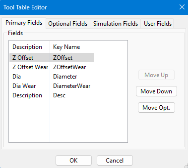
Select the Optional Field Tab.
Then select the key name XOffset and press Move Pri. Repeat for the YOffset.
Press OK and you should have X and Y tool offsets.
Now select a master tool. Then for all other tools measure the distance from the master tool in X and Y. Enter those values into the X and Y offsets.
Tool Spindle Rotation Options
Pull down View->Tool Tables to open the tool table.
Select Edit->Table Fields to open the Tool Table Editor.
Select the User Field tab.

Select Add.
Setup the tool exactly as shown below:

Press OK.
Then select View->User Fields.

Now for each tool you can select the spindle rotation options. For example, for a probe, you can select No Rotation as shown:

You will not be able to turn on the spindle with tool 1 loaded, but will get this alarm:
