MachPro X15-41-01 Wireless MPG Pendant
Contents
Each kit consists of these parts pictured below. Locate these parts before disposing of any packing.
1. Wireless receiver Antenna.
2. Antenna extension cable.
3. Wireless pendent USB receiver.
4. Hand wheel knob. (Shipped inside the battery door of the pendent)
5. 2x of AA power cells.
6. Mounting bracket and screws. (not required)
7. Wireless pendent.

Installation
All antenna connections should only be hand tightened and do not over tighten
- Insert the USB receiver into an available port on your control.
- If you are using a computer that is not installed in a metal cabinet you can attach the wireless antenna directly to the receiver.
- If the computer is inside a metal cabinet, use the included extension cable. You will need to drill an appropriately sized hole for the bulkhead connection. Attach the wireless antenna to the external bulkhead connection.
Carefully pull back and remove the protective rubber cover (8.) from the Wireless pendent (7.). Using a Phillips head screwdriver, remove the battery door (9.) and install the 2 AA power cells (5.) according the the diagram inside the battery compartment.

If desired, mount the Hand wheel knob (4.) to the MPG dial using a Phillips head screw driver.

Connecting the Pendant
The Wireless pendent (7.) and Wireless pendent USB receiver (3.) in each kit are paired together based on their ID number. This number can be found on a sticker on both devices. The USB receiver must be plugged into the control in order for the pendant to work. If the pendant cannot find the receiver when it is powered on, then a "Lost Rf" message will be printed on the pendant screen. This can be caused by the receiver not being plugged in to the control, the control being turned off, or by the distance between the pendant and receiver being too great.
Configuring the Pendant
To use the pendant you will first need to connect it to the MachPro software. Open MachPro software, pull down Configure -> Control and select the Settings tab.
select "Service" (A.) -> "Maintenance" (B.) -> "Interface Config" (C.).

When the MachPro Interface config window opens:
- Click the drop down menu
- Select the appropriate device X15-41-01 Wireless Pendant
- Click the Add button
- Click the Save button
- The pendant will load with its default configuration.
|
|
|

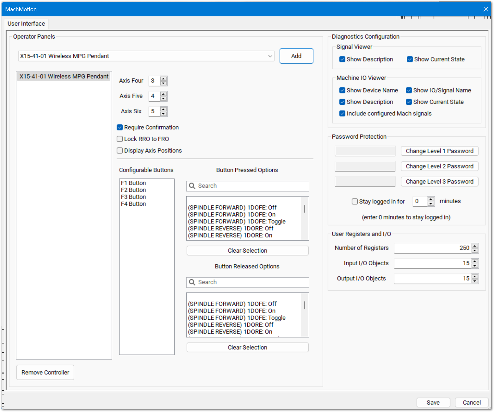
Wireless Pendent settings
The pendant has an axis selector for the MPG. The axes to jog while '4', '5', or '6' are selected is configurable here.

The checkbox for 'Require Confirmation' will force the user to press some buttons twice in order to perform their functionality, such as 'Zero Axis'. Unchecking this box will allow the user to perform these actions with only one press.

The pendant has four configurable function buttons. The options for these buttons are shown in the pressed and released options. First select which button should be configured, then select which command it should do. To create custom commands, see documentation for Function Buttons.

Press 'Save' to save changes and leave the configuration window.
Pendant Functionality
The pendant must be turned on for any functionality to work. The pendant can be turned off at any time. The pendant is turned on and off by the large silver button on the front of the pendant.
The 'Zero Axis' button will zero the axis currently selected by the axis selector knob.
The 'Feed +/-' and 'Rapid +/-' increment and decrement the overrides by 10%, unless the overrides are within 0-10%, in which case they increment and decrement by 2%.
Screen Display
There are four lines displayed on the pendant screen. The top line shows the enabled state of the control. If there is an alarm on the control, it will display that instead of the enabled state. The second line is the state of the control, such as 'Idle' or 'File Run'. The third line is the name and position of the axis currently selected by the axis selector. If no axis is selected, then this line will be blank. The fourth line will briefly show the name of the last button pressed.
If the pendant is waiting for a confirmation press, then the message about waiting for confirmation and which function is being confirmed will be displayed on lines three and four.
If the pendant cannot communicate with its USB receiver, then the screen will be cleared and a message "Lost Rf" will be displayed.
Troubleshooting
If you get the message "Lost RF", try the following items:

1. Check the USB receiver connections.
Using a Phillips head screwdriver, remove the lower back access cover from the control. Check for the USB receiver as indicated in the photo below. Check to make sure the antenna extension cable is securely connected to the USB receiver as well.
2. Replace the AA power cells:
Carefully pull back and remove the protective rubber cover (8.) from the Wireless pendent. Using a Phillips head screwdriver, remove the battery door (9.) and install 2 new AA power cells (5.) according the the diagram inside the battery compartment.
Note: Do this even if the battery life still shows two bars. It isn't always accurate.
3. Download the attached diagnostic tool "X15_connect_test.exe" file. The attachment will either show in the upper left corner of the bookstack screen

Or if you do not see that Attachments section, look for an Info tab at the top and click on that.

4. Download the file and move it to C;\Mach4\Plugins
5. Open a command prompt and move to that folder: C;\Mach4\Plugins, type in the name of the test utility and press enter to run it.

6. You will see the utility connect to the pendant and immediately disconnect from it. If you do not see the connect - disconnect sequence, check your connections on the control:
- USB receiver is plugged into the control
- Extension cord runs from the USB receiver to the bulkhead antenna jack
- The antenna is firmly attached to the antenna jack. Please be careful to not bend or damage the center conductor.
4. If you have verified that all of the physical connections are in place and the utility is still unable to connect to the pendant, then replace the pendant.