
MachPro TP400 Probe Wiring to M31 Motion Controller
{{@2007#bkmrk--1}}
How-to guide
Scope
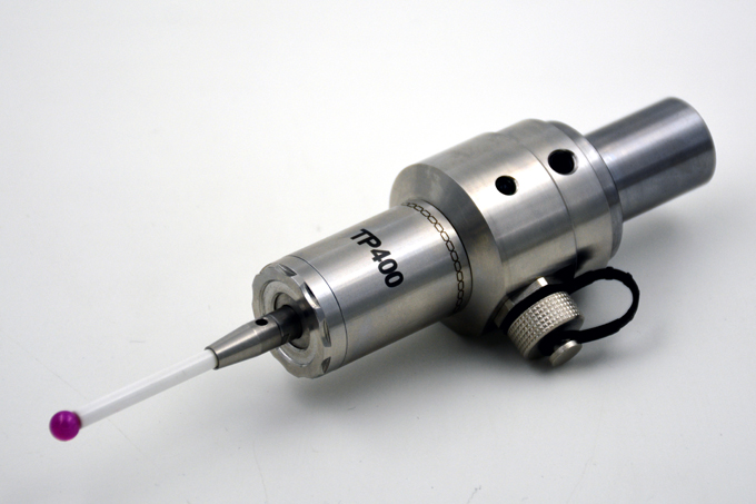
Wire a TP400 touch probe to an M31 DI (Digital Input). Configure the TP400 output as NO or NC by swapping the TP400 power wire polarity.
Definitions
-
DC (Direct Current): Electrical current that flows in one direction.
-
DI (Digital Input): An on/off input on the M31.
-
PNP (sourcing) input: An input that turns ON when the DI terminal is driven to +24 VDC relative to 0 VDC.
-
NO (Normally Open): Output is open when the probe is not triggered.
-
NC (Normally Closed): Output is closed when the probe is not triggered.
-
PE (Protective Earth): Safety ground bonded to the enclosure.
Electrical requirements
-
TP400 input power: 24 VDC ±10%.
-
TP400 output load current limit: 50 mA max.
-
M31 DI: 16 inputs (PNP sourcing), 16–2
Wire colors (manufacturer)
-
Red: Probe power lead (polarity depends on NO/NC selection)
-
Green: Probe
-
Blue: Probe status output lead
-
Black: Probe status output lead
The TP400 can reverse output logic by changing the power polarity at the probe interface.
Procedure
-
De-energize the cabinet.
-
Select an unused M31 input for the probe (example:
1DI.01.xx).
Connect TP400 power and select output type:
A. Set TP400 as NO (Normally Open)
-
-
- Connect Green to 0 VDC.
- Connect Red to +24 VDC.
-
B. Set TP400 as NC (Normally Closed)
-
-
- Connect Green to +24 VDC.
- Connect Red to 0 VDC.
-
-
Connect TP400 probe status output to the M31 PNP input:
-
Connect Black to +24 VDC (same 24 VDC supply used for M31 inputs).
-
Connect Blue to the selected M31 DI terminal (
1DI.01.xx).
Result:
-
In NO mode, the signal goes to +24 VDC only when the probe triggers.
-
In NC mode, the signal is +24 VDC at rest and goes OFF when the probe triggers.
-
-
Connect the cable shield (recommended):
-
Connect the shield/drain to the enclosure PE ground lug at the cabinet end.
-
Do not connect the shield to the M31 0 VDC terminal.
-
-
Verify operation:
-
In MachPro, monitor the chosen input state while you trigger the probe by hand.
-
If the probe is wired as NC, set the input as Active Low so the control treats the triggered state as “ON”.
-
Reference
Why NO/NC changes when you swap Red and Green
The TP400 documentation states that reversing the power polarity at the probe interface reverses the logic state of the output signal.
M31 input type
The M31 inputs are PNP sourcing, 16–24 VDC, and isolated.
Cabinet 0 VDC bonding (MachMotion recommendation)
Tie all 0 VDC terminals to a single 0 VDC/ground bar and bond that bar to PE at one point
Explanation
Shield to 0 VDC vs shield to enclosure PE
-
Shield to 0 VDC can inject noise into the input reference. This can cause unwanted probe triggers.
-
Shield to enclosure PE sends noise current to the chassis instead of the input reference. This usually improves noise immunity.
Which mode to use
-
Use NC when you want easier detection of a broken wire or loss of power (the input changes state when the circuit is not healthy).
-
Use NO when you want the input OFF at rest and ON only during probe trigger.
{{@2016}}